ISSN : 2581-7175 ©IJSRED: All Rights are Reserved Page 753
CASING AND CEMENTING JOB IN AN OIL WELL
(A CASE STUDY OF BENIN BASIN WELL 16A OF MARO OIL
COMPANY)
a
Uti L.O.,
bEsabunor O.R.,
cOgugu A.A.
a,b,cDepartment of Petroleum Engineering and Geosciences Department, Petroleum Training Institute, Effurun, Nigeria.
Abstract
For a drilling operation to be considered successful, the well must be capable of producing hydrocarbon to the surface. For this to be possible, the well must be cased and cemented using cement slurry. Also, additives play significant role in oil and gas well cementing operations. Cement additives selected for cementing operations are an integral part of sound well design, construction and well integrity. Additives are available to enhance the properties of oil well slurries and achieve successful placement between the casing and the geological formation, rapid compressive strength development and adequate zonal isolation during the lifetime of the well. This research work is focused on casing and cementing operation which is an integral and in dispensable part of drilling and completion process. The type of casings used during the actual operation went according to the proposed programme and the cementing job which was of the primary type was highly successful and went according to design. The development of the cements lurry was carried out in an ideal way based on the conditions of the formations encountered. In light of the successful nature of the casing and cementing programme carried out on Benin Basin Well 16A of Maro Oil Company, it was discovered that the practice of developing a casing strings to withstand burst, tension and collapse pressure was properly done. Thus, the developed casing strings can withstand any forceencountered.
Keywords: Casing, Cementing, oil well, force, additives, Benin Basin Well 16A
INTRODUCTION
To have a successful casing and cementing job,the design and selection of the casing should be carefully and technically done using facts gotten from calculations and bearing in mind factors such as collapse pressure, tensile load and burst pressure. After the casing has been run into the hole, there is every need for a substance (i.e., cement slurry) to be introduced between the casing and the wall of the formation to strengthen and hold the casing in place. This substance Cementing is defined as the application of a liquid slurry to various points inside or outside the casing[1-4].
ISSN : 2581-7175 ©IJSRED: All Rights are Reserved Page 754
A casing is a strong cylindrical pipethatisputin to the well bore after drilling to ensure a tight connection from the sub- surface to the surface [5-8]. It performs the following functions:
i. It prevents cave-in or wash out of the wall of theformation.
ii. It strengthens the wellbore.
iii. It prevents the contamination of fresh water sand by the drilling mud. iv. It prevents the influx of formation fluid into the wellbore.
v. It provides a means of controlling the well.
vi. It provides a flow path for the movement of the produced fluid.
vii. It helps to confine production to the wellbore.
viii. It provides a base for the attachment of the blow-out preventer.
ix. It permits selective production of the pay zone.
x. It excludes water from the producing formation.
xi. It helps to furnish a permanent bore-hole of precisely known diameter.
More over, depending on the condition of the formation and the engineer’s requirement, additives can be introduced into the cements lurry to modify and give it different characteristics such as increasing the setting time, decreasing the setting time etc.[9-12].It is very important that a good cementing job be done because the cost of a poor cementing job is very high. A good and successful cementing job depends on detailed knowledge of cement slurry, cement types, evaluation procedures and use of additives. A good cementing job performs the following function
i. It protects the casing from corrosion and enables it to be plugged.
ii. It strengthens and holds the casing in place.
MATERIALS AND METHODS
2.1 Well Description
20” Casing Cement Slurry (Class G)
Fluid description Lead cement
Density 11.5ppg
Cement yield 1.69ff3/sk
Total cement 1507sack
Slurry volume 438bbls
Water volume 287barrels
Excess 150%
Height 1118ft
Fluid description Tail cement
Density 15.8ppg
Cement yield 1.15ff3/sk
Total cement 736sack
Slurry volume 151bbls
Water volume 88barrels
Excess 150%
ISSN : 2581-7175 ©IJSRED: All Rights are Reserved Page 755 " Casing Cement Slurry (Class G)
Fluid description LeadSlurry
Density 12.8ppg
Cement yield 1.69ff3/sk
Total cement 3,286sack
Slurry volume 954bbls
Water volume 626barrels
Excess 150%
Height 5172.3ft
Fluid description Lead cement
Density 15.8ppg
Cement yield 1.15ff3/sk
Total cement 1,647sack
Slurry volume 338bbls
Water volume 196barrels
Excess 150%
Height 827.7ft
"Casing Cementing Slurry (Class G)
Fluid description Leads lurry
Density 12.5ppg
Cement yield 1.69ff3/sk
Total cement 2,079sacks
Slurry volume 604bbls
Water volume 396barrels
Excess 150%
Height 8800.5ft
Fluid description Tail Slurry
Density 15.8ppg
Cement yield 1.15ff3/sk
Total cement 1771sack
Slurry volume 363bbls
Water volume 211barrels
Excess 150%
Height 4299.44ft
2.2 Casing Cementing Job Procedure
20” Surface Casing Cementing Job Procedure
ISSN : 2581-7175 ©IJSRED: All Rights are Reserved Page 756
pressure checked for loss throughout circulation. The cement lines were flushed, and pressure tested to 500psi. The cementing job proper commenced with the pumping of water up to 400ft followed by spacer up to 600ft.Thebottomplug was dropped and pressured down with water. 438bbl of 11.5ppg leads lurry of class “G” cement+5%BWOCCaCl2 as accelerator. This was followed by 151 bbls of 15.8 ppg tails lurry consisting of class“G”cement+ 5% BWOC cacl2 as accelerator + 20 gal of Asp 742 (defoamer). The top plug was dropped and pressured down with water up to 500ft in casing. After bumping with bottom plug, the casing was pressure tested to 500psi for 5 minutes and no back flow was indicated.
" Intermediate Casing Cementing Job Procedure
The casing (13 ")was made up with 13 " casing shoe + float collar. After the casing has been installed, drilling mud was circulated twice using the same mud condition as the annular velocity when drilling. The cementing lines were pressure tested to 2500psi. The cementing job proper commenced with the pumping of water up to 400ft followed by spacer up to 600ft. The bottom plug was dropped and pressured down with water. 954bbls of 12.5ppg lead slurry of class “G” cement + 57.6gal ASP 742 + 576.3gal We ix + 550bbls marabond 21+ 1% BWOC Hec 10. This was followed by 338bbls of 15.8ppg tail slurry consisting of class “G” cement + 62gals ASP 742 + We – ix 11 drums + 12 sksmarabond 21 + 35sks Hec 10. The top plug was dropped and pressured down with water up to 500ft inside casing. After bumping the top plug, the casing was tested to 3000psi for 10 minutes and no back flow was indicated.
"Production Casing Cementing Job Procedure
After the casing and its accessories have been installed, the cement lines were flushed, and pressure tested to 5000psi. The cementing job proper commenced with the pumping of water upto 400 ft followed by spacer upto 600ft.The bottom plug was dropped and pressured down with water. 604bbls of 12.5pgg lead slurry of class “G” cement + Marabond 21 7bbls+7galASP742. This was followed by 363bbls of 15.8ppg tails lurry consisting of class “G” cement +70galsASP 742 + 5% BWOC cacl2. The top plug was dropped and pressured down with water up to 500ft inside casing. After bumping the top plug, the casing was tested to 5000psi for 10 minutes and no back flow was indicated.
2.3 Drilling Objectives
The well is programmed to achieve the following objectives:
i.Serve as a replacement well for Benin Basin Well 16A.
ii.Provide drainage points for the A8.2, A8.3 and the B1.0reservoir
iii.Produce from the oil column in the above-mentionedreservoirs
2.4 Slurry Composition and Job Quantities 20” Casing and Cementing
ISSN : 2581-7175 ©IJSRED: All Rights are Reserved Page 757 Table1 Data of 20” Casing Cementing
Component Description Concentration Job quantity
438 bbls 11.5ppg lead slurry
ASP 742 Defoamer 0.04gal/sk 53gals
We – ix Extender 0.4ga/sk 530gal
Cacl2 Accelerator 5% BWOC 113.3sks
Hec 10 Viscosifier 2% BWOC 45.3sks
Cement Class “G” 1507sks
151bbls 15.8ppg tail slurry
Cement Class “G” 736sacks
ASP 742 0.04gal/sk 20gal
" Casing Cementing
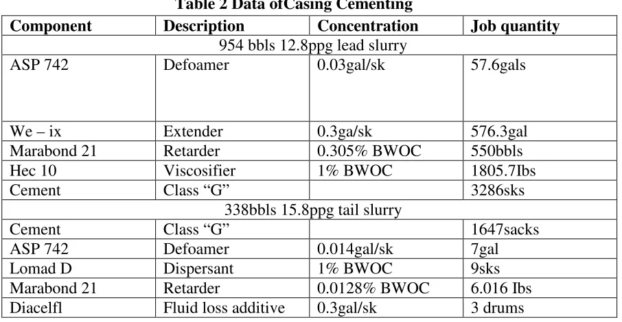
Table 2 shows the data of13 "casing cementing.
Table 2 Data ofCasing Cementing
Component Description Concentration Job quantity
954 bbls 12.8ppg lead slurry
ASP 742 Defoamer 0.03gal/sk 57.6gals
We – ix Extender 0.3ga/sk 576.3gal
Marabond 21 Retarder 0.305% BWOC 550bbls
Hec 10 Viscosifier 1% BWOC 1805.7Ibs
Cement Class “G” 3286sks
338bbls 15.8ppg tail slurry
Cement Class “G” 1647sacks
ASP 742 Defoamer 0.014gal/sk 7gal
Lomad D Dispersant 1% BWOC 9sks
Marabond 21 Retarder 0.0128% BWOC 6.016 Ibs Diacelfl Fluid loss additive 0.3gal/sk 3 drums
"Casing Cementing
Table 3 shows the data of 9 "casing cementing
Table 3 "Casing Cementing
Component Description Concentration Job quantity
604bbs of 12.5ppg lead slurry
ASP 742 Defoamer 0.02gal/sk 41.58gals
We-ix Extender 0.2gal/sk 415.8gals
ISSN : 2581-7175 ©IJSRED: All Rights are Reserved Page 758
363bbls 15.8pgg tail slurry
Component Description Concentration Job quantity
Cement Class “G” 1771 sacks
ASP 742 Defoamer 0.012gal/sk 21.252gals
Cacl2 Accelerator 5% BWOC 151.34 sks
Hec 10 Viscosifier 2% BWOC 60.536sks
RESULTS AND DISCUSSION
Data Analysis used for 20” Casing and Cementing Operation
Hole size 26”
Casing size 20”
Previous casing size 30”
Open hole excess 150%
Water per sack of lead cement 8gal/sack Water per sack of tail cement 5gal/sack
Annular Volume of Slurry Calculation
Open hole capacity between 20” casing and 26” open hole
− 1029.4
where,
D2 = diameter of open hole, and d2 = diameter of 20” casing
26 − 20
1029.4 = 0.268 /
For cased hole capacity
27.6152 − 20
1029.4 = 0.352 /
"#$% & '($%#) *+ ,-& ($ℎ+& /('0) ="# &/#( %(-& &/ + 20” 2 '($%#)1029.4
=19.12421029.4 = 0.355 /
Lead Slurry Volume
Open hole = 0.268bbl/ft x 876.06ft x 1.5 excess = 352.176bbls Cased hole = 0.352bb/ft x 242ft = 85.184bbls
ISSN : 2581-7175 ©IJSRED: All Rights are Reserved Page 759 Tail Slurry Volume
Open hole = 0.268bbl/ft x 321.94ft x 150% excess = 129.42bbls Shoe track = 0.355bbl/ft x 60ft = 21.3bbls
Total tail slurry = 150.72bbls ~ 151bbls
3('0$ + '&-&# +/ &( $ ,//4 =437.36 $ × 5.615 3/1.63 3/$0 = 1506.6 $('0$
For tail slurry, sacks of cement required will be:
= 150.72 $ ×
.67 89 ::;
1.15 3/$0 = 735.907 $('0$
Total amount of cement required = 2242.507 sacks = 2243 sacks Amount of mix water required
<+/ &( '&-&# $ ,//4 =8)($('0 + '&-&# > = 1506.6 $('0$ ?
@A; BC D @A;
::;
= 286.97 $ + E( &/
<+/ (% $ ,//4 =5)($('0 + '&-&# > = 735.907 $('0$ ×
@A; BC D @A;
::;
= 87.608 $ + E( &/
Total barrels of water required = 374.578 bbls ofwater Sacks of bentonite required
For lead slurry
Mix water contains 6% bentonite BWOCbent = 1506.6 sacks x 94Ib/sk x 0.06 = 8,497.224lb If each sack of bentonite weighs 50 lb/sk,
Then;
= 8,497.224lb50" /$0 = 169.94 $('0$ = 170 $('0$
Holesize 17½”
Casing size 13 "
Previouscasingsize 20”
Openholeexcess 150%
Water per sack ofleadcement 8gal/sack Water per sack oftailcement 5gal/sack
Annular Volume of Slurry Calculation
Open hole capacity between13 "casing and 17½” open hole=IJKLJ
7M N.D
where,
ISSN : 2581-7175 ©IJSRED: All Rights are Reserved Page 760
d2 = external diameter of casing being cemented
17.52 – 13.3752
1029.4 = 0.1237 /
P($& ℎ+ & '(Q('% 4 & E&&# 13 '($%#) (# 20” '($%#) =19.1241029.42 – 13.3752
=0.1815bbl/ft
"#$% & '($%#) *+ ,-& ($ℎ+& /('0 ="# &/#( %(-& &/ + 13 " '($%#) 1029.4
=12.5151029.42=0.1522bbl/ft
Lead Slurry
Cased hole = 0.1815bbl/ft x 1500ft = 272.25bbls Open hole = 0.1237bbl/ft x 3,672.3ft x 150% excess = 681.395bbls Total lead slurry = 953.65bbls
Tail slurry volume
Open hole = 0.1237bbl/ft x 1,767.7ft x 150% excess = 327.977bbls Shoe track
= 0.1522bbl/ft x 60ft = 9.132bbls Total tail slurry volume = 337.129bbls
3('0$ + '&-&# +/ &( $ ,//4 = 953.65 ? 5.615 3/1.63 3/$0 = 3,285.119 $('0$
For tail slurry, sacks of cement required will be:
3('0$ + '&-&# +/ &( $ ,//4 =337.129 $ × 5.615 3/1.15 3/$0 = 1,646.06899 $('0$
Total amount of cement required = 4,931.18799 sacks Amount of mix water required
=
For lead cement slurry (8gal/sack of cement =
3,285.119 $('0$ ? 8)( /$0
42)( / = 625.737 $ + E( &/
<+/ (% $ ,//4 (5)( /$0) = 1646.06899$('0$ ? 5)( /$042)( / = 195.961 $
Sacks of bentonite required For lead slurry
Mix water contains 6% bentonite BWOC bent = 3285.119 x 94 x 0.06 = 18528.07lb If each sack of bentonite weighs 50 lb/sk, then;
ISSN : 2581-7175 ©IJSRED: All Rights are Reserved Page 761 Data Analysis used for "Casing and Cementing Operation
Hole size 12¼”
Casing size 9 "
Open hole excess 150%
Water per sack of lead cement 8gal/sack Water per sack of tail cement 5gal/sack Previous casing size 13 "
Annular Volume of Slurry Calculation
Open hole capacity between9 "casing and 12¼” open hole=I – L
7M N.D
Where,
D2 = diameter of open hole,
d2 = diameter of production casing
=7 . 7M N.D – N.6 =
0.656bbl/ft
Cased hole capacity between9 "casing and 13 "casing
=12.6152 – 9.6252 1029.4 = 0.0646 /
Inside casing volume (shoe track)
=8.8352 1029.4 = 0.0758 /
Lead Slurry Volume
Cased hole = 0.0646bbl/ft x 7000ft = 452.2bbls
Open hole = 0.056bbl/ft x 1800.56ft x 150% excess = 151.247bbls Total lead slurry = 603.447bbls = 604bbls
Tail Slurry Volume
Open hole = 0.056bbl/ft x 4239.44ft x 150% excess = 358.0207bbls Shoe track = 0.0758bbl/ft x 60ft = 4.548bbls
Total tail slurry volume = 362.5687bbls
3('0$ + '&-&# +/ &( $ ,//4 =603.447 $ × 5.615 3/ 1.63 3/$0 = 2,078.745 $('0$
For tail slurry, sacks of cement required will be:
= 362.5687 $ × 5.615 3/ 1.15 3/$0 = 1770.28 $('0$
ISSN : 2581-7175 ©IJSRED: All Rights are Reserved Page 762 <+/ &( '&-&# $ ,//4 =8)($('0 + '&-&# > = 2,078.747 $('0$ ?
@A; BC D @A;
::
= 395.95 $ + E( &/ = 396 $
For tail slurry (5gal/sk)
=7bbM. BAcCB d @A;/BCD @A;/::; =210.748bbls = 211bbls Sacks of bentonite required
For lead slurry
Mix water contains 6% bentonite BWOC
bent = 2078.745sks x 94lb/sk x 0.06 = 11724.1218b If each sack of bentonite weighs 60 lb/sk, then;
=11724.121850" /$0 = 234.48 $('0$ = 235 $('0$
The oil well penetrated in the course of the development work differs in their condition of lithology, permeability, degree of saturation and other characteristics. Besides, the diversity of these factors called for the elaboration and application of various placement techniques for cementing oil wells. The effective handling of these operations leads to the reduction of well cost, increased production minimizes hazards and elimination of secondary or remedial job. In order to achieve these objectives, single stage cementing placement technique was used.
Additives Description Class G Cement (API)
It is an Api special all-purpose oil well cement designed for use up to 8000ft without activities. It is moderately to highly sulphate resistant cement, which can be modified to cover a wide range of well depths and temperature.
ASP 742 (Defoamer)
It is a liquid cement defoamer (anti – foam) used to improve slurry density control and mixability by reducing foaming.
WE – IX (Extender)
It is a liquid cement additive used in the production of a greater volume of slurry from the powered cement.
HEC 10 (Viscosifier)
ISSN : 2581-7175 ©IJSRED: All Rights are Reserved Page 763 Lomad D (Dispersant)
It is liquid high molecular weight dispersant used to lower slurry viscosity and helps provide turbulent flow properties at reduced pump rates. It also assists in fluid loss control.
CaCl2 (Accelerator)
This is used to quicken the thickening time of cement slurry
Marabond 21 (Retarder)
It is a medium to high temperature liquid cement retarder used to control the thickening time of cement slurry at temperature from 800F to 3000F.
Diacelfl (Fluid Loss Control)
It is a liquid cement fluid loss and gas migration control agent used up to 3500F
CONCLUSION
Based on my findings, and the result of the analysis of the case study, it was concluded that the practice of designing strings to withstands burst, tensional and collapse pressure were properly carried out. The development of the cement slurry was carried out in an ideal way based on the conditions of the formation encountered. Also, proper description and use of additives according to laboratory analysis was also done.
RECOMMENDATIONS
Based on a careful analysis using Benin Basin Well 16A as a case in this research work, we therefore recommend the following:
i. Good practice for designing casing strings that can withstand any force (burst, tension and collapse) should be maintained.
ii.Type and quantities of additives to be used in a cementing operation should be followed strictly as that is an indispensable part of the cementing operation.
REFERENCES
[1]Bett E.K. (2010). Geothermal Well Cementing Materials and Placement Techniques Geothermal
Training Programme-Report 10:99-130.
[2]Joel O.F. (2009). The Secondary Effects of Lignosulfonate Cement Retarder on Cement Slurry Properties.
Journal of Engineering and Applied Sciences 4:1-7.
[3]Roshan H., Asef, M.R. (2010). Characteristics of Oil Well Cement Slurry Using CMC. Journal of
Society of Petroleum Engineers Drilling and Completion SPE 25:328-335.
ISSN : 2581-7175 ©IJSRED: All Rights are Reserved Page 764 Case Study of Well 2L of the Shell Petroleum Development Company (SPDC) Western Operation
Division in the Niger Delta, Nigeria). SSRG International Journal of Geoinformatics and Geological Science (SSRG-IJGGS), 6(2):1-5
[5]Logvinenko, S. (1974): Well cementing engineering and technology”, fifth edition, volume four. High
School Publishing House, Moscow.Pp.97.
[6]Smith, R. C. (1984). Successful primary cementing can be a reality”, tenth edition, volume one. Pamwell
Publishing Company, Tusla, Oklahoma,pp.1185-1187.
[7]Cowan K.M., and Eoff L. (1993). Surfactants: Additives to Improve the Performance Properties of
Cements, Society of Petroleum Engineers. International Symposium on Oilfield Chemistry New Orleans LA. USA317-327.
[8]Lake L.W., and Mitchell R.F. (2006). Petroleum Engineering Handbook, Drilling Engineering,
Society of Petroleum Engineers 2:395-410.
[9]Ludwig, N.C. (1951). Effects of Sodium Chloride on Setting Properties of Oil-well Cements Paper
Presented at the Spring Meeting of the Mid-Continent District Division of Production. Amarillo Texas20-27.
[10] Kutasov I.M., and Eppelbaum, L.V. (2014). Temperature Regime of Boreholes: Cementing of
Production Liners
ProceedingsofThirty-NinthWorkshoponGeothermalReservoirEngineeringStanford.UniversityStanfordCalifornia 1-5.
[11] Coveney, P.V., and Humphries, W. (1996). Molecular Modelling of the Mechanism of Action of
Phosphate Retarders on Hydrating Cements. Journal of the Chemical Society Faraday Transactions 92:831-841.
[12] KhanB., and UllahM.(2004).Effect of a Retarding Admixture on the Setting Time of Cement Pastesin