Event-driven control
in theory and practice
Trade-offs in software and control performance
PROEFSCHRIFT
ter verkrijging van de graad van doctor aan de Technische Universiteit Eindhoven, op gezag van de Rector Magnificus, prof.dr.ir. C.J. van Duijn, voor een
commissie aangewezen door het College voor Promoties in het openbaar te verdedigen op dinsdag 19 december 2006 om 16.00 uur
door
Jacobus Henk Sandee
geboren te Wissenkerkeprof.dr.ir. P.P.J. van den Bosch
Copromotor:
dr.ir. W.P.M.H. Heemels
CIP-DATA LIBRARY TECHNISCHE UNIVERSITEIT EINDHOVEN Sandee, Jacobus H.
Event-driven control in theory and practice : trade-offs in software and control performance / by Jacobus Henk Sandee. - Eindhoven : Technische Universiteit Eindhoven, 2006.
Proefschrift. - ISBN-10: 90-386-1933-2 ISBN-13: 978-90-386-1933-0
NUR 959
Trefw.: discrete regelsystemen / reactieve computersystemen / bemonsterde regelsystemen / randapparatuur ; printers.
Subject headings: discrete event systems / computerised control / sampled data systems / printing industry.
Copyright c°2006 by J.H. Sandee
This PhD-study has been carried out as part of the Boderc project under the
responsibility of the Embedded Systems Institute. This project is partially supported by the Dutch Ministry of Economic Affairs under the Senter TS program.
Preface
This PhD-research is part of the Boderc research project: Beyond the Ordinary: De-sign of Embedded Real-time Control; coordinated by the Embedded Systems Institute. The project aims at developing a model-based methodology to support early decisions over multiple disciplines in the design of high-tech systems. A high speed document printing system of Oc´e Technologies BV is taken as a case study and acts as the main industrial driver for the project.
According to the Boderc project plan, modern high-tech systems, such as for ex-ample encountered in high speed digital printing, rely during the design on the input from different disciplines like electrical engineering, mechanical engineering, soft-ware engineering, and control engineering. These disciplines use different models of computation, such as differential equations, automata and finite state machines. Aca-demic research is needed to create models that can effectively bridge the gap between the different disciplines, by mixing different models of computation at the right level of abstraction. However, it is not yet understood how the complete design process can be done under demanding industrial product circumstances. This is the overall topic of the Boderc project. This PhD-thesis specifically focusses on the system design aspects where the disciplines software and control engineering are involved. This is visualized as one of the three axis of a pyramid in the figure below.
theory practice system level / few details component level / many details control software
To make multi-disciplinary design choices, a system architect typically works with high-level system descriptions, with only few details, as well as with low-level com-ponent models, including lots of details. This is illustrated on the vertical axis of the pyramid. To make well-founded trade-offs, he has to be able to reason at these dif-ferent levels of detail and iterate in short cycles. These difdif-ferent levels can also be observed in this thesis as it presents results at the system level (chapters 1-3 and 7), as well as at the component level (chapters 4-6). The system level results should typically be placed in the emerging field ofsystems engineering, while the lower level results are especially focussed on the domain ofcontrol engineering, includingsoftware en-gineeringaspects.
In the multi-disciplinary design of high-tech systems, it is important that academia works closely together with industry. Industry needs the highly specialized, often the-oretical knowledge from academia, and academia needs the industrial environment to focus on therightproblems and to test their ideas within industrial practice and constraints. These aspects can also be recognized in this thesis as the presented con-cepts are well-founded by academic proofs at several points, as well as validated via practical experiments in the industrial environment of printer development. This is indicated at the third axis of the pyramid. The balls in the pyramid indicate how a typical chapter outline of this thesis moves through the pyramid. This process is also observed in practice when designing high-tech systems.
The pyramid also reflects the nature of the Boderc project: It covers the broad range from system level to mono-disciplinary knowledge on one hand, and from aca-demic to industrial results on the other.
Abstract
Event-driven control in theory and practice
Trade-offs in software and control performance
Feedback control algorithms are indispensable for the proper functioning of many industrial high-tech systems like copiers, wafer steppers and so on. Most research in digital feedback control considers periodic or time-driven control systems, where continuous-time signals are represented by their sampled values at a fixed frequency. In most applications, these digital control algorithms are implemented in a real-time embedded software environment. As a consequence of the time-driven nature of con-trollers, control engineers pose strong, non-negotiable requirements on the real-time implementations of their algorithms as the required control performance can be guar-anteed in this manner. This might lead to non-optimal solutions if the design problem is considered from a broader multi-disciplinary system perspective. As an example, time-driven controllers perform control calculations all the time at a fixed rate, so also when nothing significant has happened in the process. This is clearly an unneces-sary waste of resources like processor load and communication bus load and thus not optimal if these aspects are considered as well.
To reduce the severe real-time constraints imposed by the control engineer and the accompanying disadvantages, this thesis proposes to drop the strict requirement of equidistant sampling. This enables the designers to make better balanced multi-disciplinary trade-offs resulting in a better overall system performance and reduced cost price. By not requiring equidistant sampling, one could for instance vary the sample frequency over time and dynamically schedule the control algorithms in order to optimize over processor load. Another option is to perform a control update when new measurement data arrives. In this manner quantization effects and latencies are reduced considerably, which can reduce the required sensor resolution and thus the system cost price. As it is now an event (e.g. the arrival of a new measurement), rather than the elapse of time, that triggers the controller to perform an update, this type of feedback controllers is calledevent-driven control.
In this thesis, we present two different event-driven control structures. The first one is sensor-basedevent-driven control in the sense that the control update is trig-gered by the arrival of new sensor data. In particular, this control structure is applied to accurately control a motor, based on an (extremely) low resolution encoder. The control design is based on transforming the system equations from the time domain to the angular position (spatial) domain. As controller updates are synchronous with re-spect to the angular position of the motor, we can apply variations on classical control theory to design and tune the controller. As a result of the transformation, the typical
control measures that we obtain from analysis, are formulated in the spatial domain. For instance, the bandwidth of the controller is not expressed in Hertz (s−1) anymore, but inrad−1 and settling time is replaced by settlingdistance. For many high-tech systems these spatial measures directly relate to thereal performance requirements. Moreover, disturbances are often more easily formulated in terms of angular position than in terms of time, which has clear advantages from a modeling point of view. To validate the theory, the controller is implemented on a high speed document print-ing system, to accurately control a motor based on an encoder resolution of only 1 pulse per revolution. By means of analysis, simulation and measurements we show that the control performance is similar to the initially proposed industrial controller that is based on a much higher encoder resolution. Moreover, we show that the pro-posed event-driven controller involves a significant lower processor load and hence outperforms the time-driven controller from a system perspective.
The aim of the second type of event-driven controllers is to reduce the resource uti-lization for the controller tasks, such as processor load and communication bus load. The main idea is to only update the controller when it is necessary from a control performance point of view. For instance, we propose event-driven controllers that do not update the control value when the tracking/stabilization error is below a certain threshold. By choosing this threshold, a trade-off can be made between control per-formance and processor load. To get insight in this trade-off, theory is presented to an-alyze the control performance of these event-driven control loops in terms of ultimate bounds on the tracking/stabilization error. The theory is based on inferring properties (like robust positive invariance, ultimate boundedness and convergence indices) for the event-driven controlled system from discrete-time linear systems and piecewise linear systems. Next to the theoretical analysis, simulations and experiments are carried out on a printer paper path test-setup. It is shown that for the particular application the av-erage processing time, needed to execute the controller tasks, was reduced by a factor 2 without significant degradation of the control performance in comparison to a time-driven implementation. Moreover, we developed a method to accurately predict the processor load for different processing platforms. This method is based on simulation models and micro measurements on the processing platform, such that the processor load can be estimated prior to implementing the controller on the platform.
Next to these contributions in the field of event-driven control, a system engineer-ing technique called “threads of reasonengineer-ing” is extended and applied to the printer case study to achieve a focus on the right issues and trade-offs in a design.
In summary, two types of event-driven controllers are theoretically analyzed and experimentally validated on a prototype document printing system. The results clearly indicate the potential benefits of event-driven control with respect to the overall system performance and in making trade-offs between control performance, software perfor-mance and cost price.
Contents
Preface iii
Abstract v
1 Introduction 1
1.1 Trade-offs in software and control performance . . . 3
1.2 Event-driven control . . . 6
1.3 Experimental and industrial validation . . . 7
1.4 Scope and outline . . . 9
2 How to focus on the right trade-offs 13 2.1 Introduction . . . 13
2.2 Problem scope . . . 15
2.3 The technique of threads of reasoning . . . 16
2.4 Threads of reasoning for the case study . . . 23
2.5 Conclusions . . . 28
3 Event-driven control 31 3.1 Introduction . . . 31
3.2 Examples of event-driven control . . . 33
3.3 Event-driven control in the case study . . . 36
3.4 Contributions in event-driven control . . . 38
4 Sensor-based event-driven control 41 4.1 Introduction . . . 41 4.2 Problem formulation . . . 45 4.3 Observer-based control . . . 47 4.4 Event-driven control . . . 50 4.5 Implementation issues . . . 60 4.6 Simulation results . . . 63 4.7 Measurement results . . . 66
4.8 Selection of quantization frequency . . . 67
4.9 Discussion . . . 74
5 Event-driven control to reduce resource utilization 79 5.1 Introduction . . . 79 5.2 Motivating examples . . . 81 5.3 Preliminaries . . . 87 5.4 Problem formulation . . . 88 5.5 Approach . . . 90
5.6 Main results for non-uniform mechanism . . . 92
5.7 Main results for the uniform mechanism . . . 93
5.8 Including intersample behavior . . . 102
5.9 Computational aspects . . . 103
5.10 Tuning of the controller . . . 105
5.11 Examples . . . 107
5.12 Conclusions . . . 110
6 Processor load for event-driven controllers 113 6.1 Introduction . . . 113 6.2 Event-driven controller . . . 115 6.3 Experimental setup . . . 116 6.4 Simulation results . . . 119 6.5 Prediction . . . 122 6.6 Experiments . . . 125 6.7 Discussion . . . 131 6.8 Conclusions . . . 134
7 Conclusions and recommendations 135 7.1 Conclusions . . . 135
7.2 Recommendations . . . 138
Bibliography 141
Samenvatting 147
Acknowledgements / Dankwoord 151
1
Introduction
1.1 Trade-offs in software and control performance 1.2 Event-driven control
1.3 Experimental and industrial validation
1.4 Scope and outline
Control algorithms are indispensable for the proper functioning of many high-tech applications, such as automobiles, airplanes, home applications (refrigerator, washing machine, vacuum cleaner), industrial plants, and for instance copiers. Within these high-tech systems, a broad variety of controllers can be found. For instance in a copier, where most controllers are implemented to control the velocity of a motor. These mo-tor controllers are mainly found in the paper path where they drive rollers to transport sheets of paper. However, throughout the whole copier, physical parts are moving by the actuation of a motor. For instance in the scanner, where an array of sensors scans the media, or in the finisher, where paper trays are moved to the right position to catch the sheets of paper. Next to controlling motors, controllers are applied for various other purposes in the copier. One example is the temperature control at the location where the image is fused onto the sheet. Also controllers can be found that are not controlling a physical element of the copier, but for instance take care of synchronized timing over the multiple processors in the system.
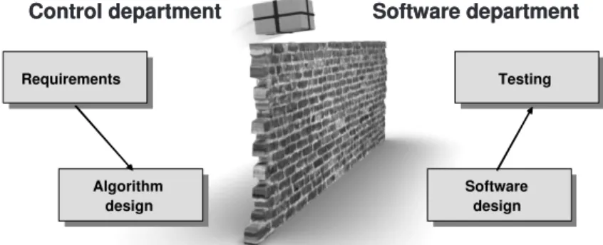
Most of these control algorithms have in common that they need to be executed on a real-time software processing platform, under strong real-time conditions to guar-antee their required control performance. The major reason is that most controller design methods are based on the requirement that the controller sample moments are uniformly distributed over time, i.e. having fixed sample intervals. Stating differently, effects like timing variation (jitter), which are inevitable in most software implemen-tations, are not included in most analysis and synthesis methods. As a consequence, control engineers pose strong, non-negotiable requirements on the real-time imple-mentations of their algorithms. This is illustrated in figure 1.1, which depicts the con-trol algorithm as a package that is thrown over a brick wall to the software department
Control department Software department
Control department Software department
Requirements Requirements Algorithm design Algorithm design Testing Testing Software design Software design
Figure 1.1:“...control engineers pose strong, non-negotiable requirements on the real-time im-plementations of their algorithms...”
that has to implement and test the algorithm.
An emerging field of research in control engineering is to take the real-time im-plementation difficulties into account. To be able to guarantee a certain overall system performance, control engineers should be aware of the difficulties in implementing control algorithms with hard real-time requirements in a software environment where resources like processing power and communication bandwidth are shared with other running processes. It is common for them to test their algorithms on dedicated hard-ware with enough processing power to meet the requirements. They are most often not aware of the underlying scheduling techniques that are used to implement the al-gorithm on the final product. This means that control engineers typically do not take the needs of the scheduler into account during the design or make use of its properties (e.g. knowledge of deadlines).
But, the reverse is also true: Many (control) software designers have insufficient knowledge of which controller requirements can be relaxed to better fit the under-lying software architecture. One example can be found in the choice of the sample frequency. From a control performance point of view, many algorithms are hardly affected by a small variation in the sample frequency, but this might make software implementations a lot easier. Also, control engineers have lots of knowledge about (constant) delays/latencies, that can be handled by the controller, but these are often not communicated to the software designers. Therefore, effective communication is essential, as it is very hard for one person to have extensive knowledge in both
disci-1.1. Trade-offs in software and control performance 3
plines. Next to effective communication, however, control design methods should be available to specifically deal with these multi-disciplinary design aspects.
1.1 Trade-offs in software and control
perfor-mance
There are various issues that make the implementation of controllers difficult on em-bedded platforms with limited resources. In the previous section we have already mentioned some of them; both from the perspectives of the control engineer as well as from the (control) software designer. These issues result in important trade-offs that affect both the control performance (i.e. tracking, stabilization, disturbance rejection, etc) and the software performance (i.e. processor load, response times, etc) and have to be dealt with in the system design. The main trade-offs are found in:
Sample frequency selection
The sample frequency of the control updates has a strong relation to the re-quired controller bandwidth (the frequency up to which reference signals can be tracked and disturbances are suppressed) [26]. When the sample frequency is increased, the obtainable bandwidth can also be increased by carefully tun-ing the controller. Often though, the chosen sample frequency is considerably larger than strictly necessary. Typically, the sample frequency is based on rules-of-thumb; for instance at 6 times the desired closed-loop bandwidth when per-forming discrete-time controller design [25]. In industrial practice the sample frequency might even be chosen at≥40 times the desired closed-loop bandwidth to be at the “safe side”.
The reason to lower the sample frequency is obvious in applications where pro-cessing power is limited. Each time the control algorithm is executed, a set of tasks needs to be processed, which takes time. The more complex the algo-rithm, the lower the maximum allowable sample frequency generally is, as it takes more time to execute more complex algorithms (see also ‘Time-varying delays’ below). Therefore, the main trade-off that can be identified in the se-lection of the controller sample frequency is between control performance on the one hand and processor load on the other. Studies are carried out to lower the sample frequency requirement by designing the controller in discrete-time, while taking into account the continuous-time behavior of the controlled system
(see e.g. [55]).
Next to the available processing power for the control algorithm, a constraining factor for the sample frequency selection is the limited availability of timer inter-rupts on the processing platform to trigger the control updates. This is generally the case when more tasks are running on the same processor. It can therefore be favorable to have periodic tasks running on a multiple of each others sample frequency. This indicates some of the demands that software designers might impose on the sample frequency, which are in current practice often not taken into account when designing a controller.
Time-varying delays
Time-varying delays in control implementations are inevitable because of the fact that the execution of tasks on a processor simply takes time. When process-ing power is limited, often choices have to be made about the complexity of the chosen control algorithm. In many situations, complex control algorithms have the advantage to be able to perform more demanding tasks and achieve a higher control performance. However, when the complexity is increased, the execution time increases, with which the duration until the moment that the actuator sig-nal is updated increases as well. This increased delay generally influences the control performance in a negative way. In practice, this trade-off is taken into account rarely. Note that in the real-time software community one often refers to (fixed) delays as “latencies”, and the term “jitter” is used for the time-varying part of the delay.
Other important reasons for (varying) delays caused by the software imple-mentation are: communication of data over a network [86], scheduling (see e.g. [78] in which the effects of various schedulers on the control performance is analyzed), and memory usage (including cache). All these complex issues contribute to the achievable control performance and to the performance of the total system, which makes the controller implementation a difficult multi-disciplinary problem.
The academic literature about control under time-varying delays is expanding rapidly. This topic is particularly of interest as more and more often wireless networks with limited bandwidth are used to communicate sensor and actuator signals over a distance. A nice overview paper of various techniques to analyze the stability of networked control systems is found in [86]. This paper also
de-1.1. Trade-offs in software and control performance 5
scribes different types of networks and their influence on the controlled system. In industrial practice, however, control engineers typically only take constant delays into account when designing the controller. The effects of jitter are (at best) quantified in simulations (see e.g. [8]). Another option is to implement the controller with a large but constant delay between measurement and actuation, by implementing a fixed delay that is larger than the maximum expected jitter. In these systems, one often chooses one complete sample period delay.
Quantization
Quantization is often caused by the limited resolution of sensors, but also the software implementation and communication mechanisms can be important rea-sons. When a controller is implemented on a specific platform we have to deal with a limited resolution for the representation of variables. This is caused by the limited word length. Depending on the processor, calculations will cost more time for bigger word lengths. Therefore, increasing the word length is an advantage for the control performance because of reduced quantization, but might as well be a disadvantage because of the increased computation time. For communicating data over a network with limited capacity, the same reasoning applies.
In control theory, quantization is an effect that is known and has been studied thoroughly since the 1950’s. In [25] several methods are discussed how to an-alyze the control performance of systems affected by quantization. In practice, however, a quantizer is often implemented in simulation to observe its effect on the system behavior. This is an important step, because quantization intro-duces tracking errors and can cause nasty symptoms (like limit cycles) in the controlled system. Unfortunately, it is also a step that is often overlooked in the early design phases.
Above, we have mentioned various trade-offs between software and control per-formance in the context of sample frequency selection, time-varying delays and quan-tization. Still, it lists only a small subset of all the trade-offs that have to be dealt with in the system design, even when only considering the implementation of embedded feedback control algorithms. Moreover, for a high-tech system, multiple disciplines are involved in the trade-off making process. They are all responsible for a specific as-pect of the design, e.g. the electronic design, mechanical design and software design, while physics and chemistry constitute clear constraints as well. Designs are often
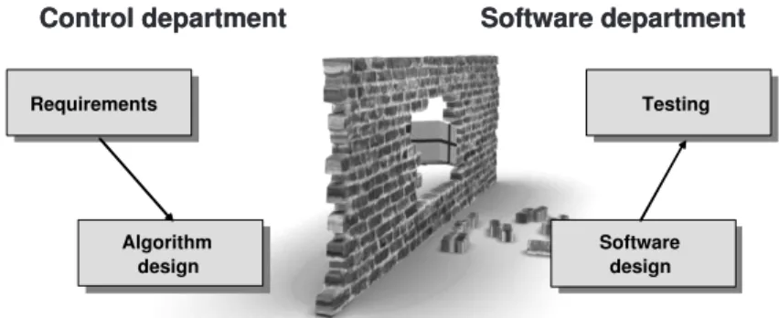
Control department Software department
Control department Software department
Requirements Requirements Algorithm design Algorithm design Testing Testing Software design Software design
Figure 1.2:“...a step towards breaking down the wall between both disciplines...”
made in parallel by multiple groups of people. Considering the complexity of these systems due to size (one may think typically of millions lines of code and thousands of components like bolts, nuts, etc) and due to many multi-disciplinary design decisions, making these multi-disciplinary trade-offs is a tremendous task and a real challenge. As it is in practice impossible to analyze every trade-off thoroughly due to limited design time and effort, one is forced to zoom in on the most important issues and not waste time on non-issues. Therefore, methods should be available that support in fo-cussing on the most important and most critical issues in a design. This is an essential part in the discipline system engineering [42], as discussed in chapter 2.
1.2 Event-driven control
When considering the trade-offs between software and control engineering, an im-provement would be to have design methods for control algorithms that also take the requirements of the software implementation into account. On the other hand, we need design methods for software that deal with the control requirements. Researchers in software and control engineering are becoming increasingly aware of this need for an integrated scientific and technological perspective on the role that computers play in control systems and that control can play in computer systems [75]. The research presented in this thesis focusses on breaking down parts of the wall between both disciplines (figure 1.2), by relaxing one of the most stringent conditions that control engineers impose: a fixed sample frequency.
1.3. Experimental and industrial validation 7
We propose control algorithms that do not require that sample moments are uni-formly distributed over time. We claim that this enables the engineers to make better trade-offs in order to achieve a better overallsystem performance. By not requiring equidistant sampling, one could for instance vary the sample frequency over time and therefore choose to dynamically schedule the control algorithms in order to optimize over processor load. Another option is to design the controller such that it responds faster to acquired measurement data with which quantization effects and latencies are reduced considerably.
These controllers we callevent-drivencontrollers, as it is anevent, rather than the progression of time, that triggers the controller to perform an update. As event-driven control loops typically deal with discrete events having strong interaction with the continuous-time dynamics of the plant, they can be considered as a specific class of hybrid systems. The classical controllers that perform equidistant sampling we call
time-driven.
Various examples found in literature promote the use of event-driven controllers. For instance, when the event-based sampling is caused by the measurement method used (see e.g. [16, 24, 36, 56, 60]). Also the physical nature of the process that is controlled can be a source for event-based sampling (see e.g. the examples in [21]). When control loops are implemented on embedded platform with control loops closed over networks, it is often very difficult to implement time-driven algorithms, as dis-cussed in [17, 86]. Although we do find examples of event-driven control in literature, hardly any theory on control performance analysis is found. The aim of this thesis is to contribute in filling this gap.
Event-driven controllers better fit the new technology in software and computing platforms, which is focusing on the use of event-based systems. The reason is often to save on computing power and communication load. This is done by adapting existing platforms for event-driven operating systems [20] or by creating new platforms without the need for a system clock [30].
In chapter 3 we will give a more extensive introduction to event-driven controllers and their potential value in practice.
1.3 Experimental and industrial validation
The application context, that is used in this thesis to validate the theoretical results on event-driven control, is best characterized by document printing systems that areFigure 1.3:The Oc´e VarioPrint 2090.
highly productive, reliable, and user-friendly. A picture of such a printer is shown in figure 1.3. These systems can print on several sizes of media, different weights, automatically on both sides and include stapling, booklet production, or other types of finishing. In order to be perceived as reliable devices, such printers must be very robust with respect to variations in media, and stochastic variations in timing parameters that relate to paper transport must be controlled up to a high degree. As the printing speed is rather high (typically above 1 image per second), timing requirements are tight and advanced mechatronics are indispensable. This becomes the more apparent if one realizes that the positioning of images on paper has tolerances well below 1 mm.
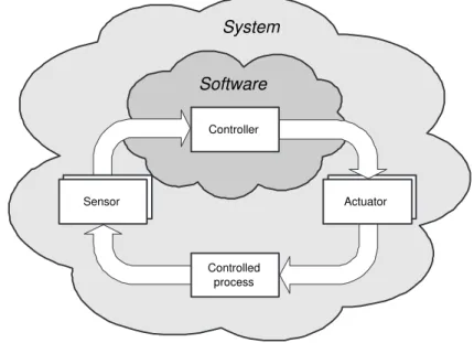
When considering the embedded control of these systems, one should think of con-trolling multiple sheets that travel through the paper path simultaneously, while keep-ing them synchronized with the imagkeep-ing process. In figure 1.4 a schematic overview of the printer is presented. When the printer is in normal operation, a sheet is separated from the trays in the paper input module, after which it is sent to the paper path that transports the sheets accurately in the direction of the print engine, where the image is fused on a sheet of paper. After that, the sheet is turned for duplex printing, or transported by the paper path to the finisher.
1.4. Scope and outline 9
print engine paper path
paper input module finisher image processing image fuse sensors rollers motors control software paper motor
Figure 1.4:Overview of the different components in the printer.
1.4 Scope and outline
Research hypothesisEvent-driven control improves the overallsystem performanceover traditional time-driven control by relaxing one of the most stringent conditions that control engineers impose: a fixed sample frequency.
For the overallsystem performancewe consider the system aspects that are affected by the controller’s implementation, which particularly are:
• control performance (in terms of tracking, stabilization, disturbance rejection, etc), and
• software performance (in terms of processor load),
• amongst other aspects, like communication bus load and system cost price. One of the main challenges in this context is to create possibilities to make better balanced trade-offs between the software and control performance. For this, theory to analyze the performance in both areas, as well as practical design rules to imple-ment the event-driven controllers in industry are developed. The results are validated on an industrial high speed document printing system. Next to these contributions in the field of “implementation-aware control”, a system engineering technique called “threads of reasoning” is extended and applied to the printer case study to achieve fo-cus on the right issues and trade-offs in the design. Making trade-offs is a fundamental step for any system engineer and this technique is demonstrated to be supportive in this process.
The contributions of the individual chapters are: Chapter 2: How to focus on the right trade-offs
In the design of technology intensive products (like printers) one searches for a product that satisfies the product requirements as well as the business drivers. The main need in an early design phase is to bring structure in the typical chaos of uncertainty and the huge amount of realization options present. Potential realization choices all have advantages and disadvantages, which cause conflicts in the design. The earlier the essential conflicts are identified, the better it is. Turning them from implicit to explicit helps the system architect in making the trade-off consciously or at least in selecting the most important conflicts that require further in-depth investigation. In this respect we extend the effectiveness of a technique called “threads of reasoning” in the printer case study.
This chapter is based on the work published in the proceedings of the 16th an-nual international symposium of the International Council On Systems Engi-neering (INCOSE) [72].
Chapter 3: Event-driven control
This chapter introduces and motivates the use of event-driven control, as op-posed to traditional time-driven controllers. The aim of event-driven control is to create a better balance between control performance on one hand, and other system aspects (such as the processor load, communication load, and system cost price) on the other, to achieve a better overallsystem performance. This is done by relaxing the stringent condition of equidistant sampling at high fre-quencies when applying time-driven control. It is illustrated that event-driven control can reduce the work-load (e.g. processor load, communication bus load) and that response times are reduced as well.
Chapter 4: Sensor-based event-driven control
One of the challenging problems in the design of a printer and many other mo-tion systems is the servo control of several motors at high accuracy. Because of cost price requirements conventional solutions are often not feasible anymore. High resolution encoders are far too expensive and high sample frequencies are prohibitive as controllers have to run on low-cost processors with processing power that is shared with many other tasks. As a possible solution, we present an event-driven controller that is based on an (extremely) low resolution
en-1.4. Scope and outline 11
coder. The control value is updated at each moment that an encoder pulse is detected, yielding zero measurement error. Although this approach can be ap-plied in general, we focus on the printer case study, in which we accurately control a DC-motor based on an encoder having a resolution of only 1 pulse per revolution. By means of analysis, simulation and measurements we show that the control performance is similar to the initially proposed industrial controller that is based on a much higher encoder resolution. On top of this, we show that the proposed event-driven controller involves a significant lower processor load, i.e. a better software performance.
This chapter is based on the work submitted for journal publication [73]. Chapter 5: Event-driven control to reduce resource utilization
In spite of the various benefits of using event-driven control, its application in practice is hampered by the lack of a system theory for event-based sampled con-trol systems. The latter is mainly due to the fact that the analysis is mathemat-ically more complicated than for time-driven control loops. To add in building up an event-based system theory, this chapter considers a specific event-driven control scheme for perturbed linear systems. The event-driven control scheme updates the control value only when the (tracking or stabilization) error is large, but not when this error is small. In this way, the average processor and/or com-munication load can be reduced considerably. The analysis in this chapter is aimed at the control performance in terms of practical stability (ultimate bound-edness). By using the derived results, the event-driven controller can be tuned to get satisfactorily transient behavior and desirable ultimate bounds on one hand, while reducing the required resource utilization for its implementation on the other. Several examples illustrate the theory.
This chapter is partially based on the work that appeared in the proceedings of the American Control Conferences 2005 [70] and 2006 [38], and is submitted for journal publication [40].
Chapter 6: Processor load for event-driven controllers
In literature [4, 22, 41, 66], some proposals are made for event-driven controllers to reduce the number of control updates without deteriorating the control per-formance significantly. The assumption is made that the reduction in control up-dates results in a reduction of the processor load needed for its implementation.
However, this is unclear as event-driven control typically introduces some over-head and experimental validation of the reduced processor load for event-driven controllers has not been presented in literature so far. This chapter contributes in filling this gap. Simulations, as well as experiments on a printer paper path test setup, show that a reduction in the number of control updates indeed results in a considerable reduction of the processor load, with only a small decrease of con-trol performance. Furthermore, a method is presented to predict the processor load accurately, without having to implement the controller on a test setup. This chapter is partially based on the work published in the proceedings of the IEEE Conference on Control and Applications 2006 [71] and is submitted for journal publication [74].
Chapter 7: Conclusions and recommendations
2
How to focus on the right
trade-offs
1
2.1 Introduction 2.2 Problem scope
2.3 The technique of threads of reasoning
2.4 Threads of reasoning for the case study
2.5 Conclusions
2.1 Introduction
The complexity of products being designed by industry today is increasing at an as-tonishing rate. The search is for a product that will satisfy the design drivers within certain margins. Design drivers are the important system aspects on which design de-cisions are based. Examples are: development costs, production costs, time-to-market, throughput, response time, productivity, physical dimensions, power consumption, noise production, and so on. Often, design drivers are conflicting, so that trade-offs must be made.
The main need in the design process of a product is to bring structure in the typ-ical chaos of uncertainty and the huge amount of realization options present. This is most profound in the early design phase. Even typical product requirements might be uncertain in the sense that they are only known up to a certain degree or are still open for discussion. Potential solutions or applied technologies all have advantages as well as disadvantages, which causesconflictsin the design. Aconflictis the situation where a specific design choice influences one or more design drivers positively, while influencing others in a negative way. For instance, in the design of a printer one might consider using stepper motors, DC servo-motors or a combination of both for driving the sheets of paper through the paper path. While stepper motors have the advantage
1This chapter is based on the work published in the proceedings of the 16th annual international
of being cheaper (particularly as they do not require expensive encoders and because of their long lifetime), they are in general less accurate in positioning the sheets of paper. This causes a conflict between the design driversprinting accuracyon the one hand andcost priceon the other. Of course, more design drivers might play a role in such a decision (e.g. size, power consumption, etc).
This chapter applies the technique ofthreads of reasoning[58] to find such con-flicts in the design of the paper flow control in the printer. The technique aims at composing a clear overview of how the conflicts relate to the design drivers. As these relations typically involve multiple design drivers, design choices and their conse-quences, we refer to these relations as threads. The technique is called threads of
reasoningas the threads typically reveal thereasoningapplied by the systems engi-neer. The details of the technique are presented together with a 5-step iterative scheme on how to create the threads. Once the main conflicts are identifiedqualitatively, a further quantitativeinvestigation by modeling and measurements is necessary. The specific model-based investigations are only indicated briefly.
In several communities there are alternative and / or related techniques available to identify the main relations and conflicts in the design of a product. For instance, in requirement engineering and more particular in [85] one uses the term “problem bundle” that has similar properties as a thread of reasoning. In [85] these bundles are adopted for structuring a design problem at hand and relating this to the solution space. In product line engineering one has methods like Pulse (see e.g. [9]) and in the system engineering community one uses risk management approaches (see [42, Ch. 6]). These techniques create similar overviews, but more retrospective. Threads of reasoning, on the other hand, is applied throughout the complete system design process and in the various design phases. Therefore, the threads are not static, but continuously changing as the design evolves.
Also in VAP (visual architecting process) (see [57, Ch. 2]) and in ARES (Architec-tural Reasoning for Embedded Software) [43] related techniques can be found which are especially focussed on software design problems. In TRIZ [3] two important con-cepts are introduced that are also crucial in our reasoning method: formulating the “ideal” solution to a problem and identifying the conflicts in realizing the ideal prod-uct. Quality function deployment (QFD) [65] relates product requirements of the cus-tomer to design choices, which from an abstract point of view resembles the reasoning used in this chapter. However, a distinguishing feature of threads of reasoning is that it is graph- instead of matrix-oriented. Matrix-oriented techniques have the tendency
2.2. Problem scope 15
that the number of relationships easily explodes and one easily looses overview of the essential threads. Threads of reasoning is particularly focused on keeping only the essential conflicts, which we consider an advantage. As a consequence, it is possible to graphically represent the overview of the most important design issues. Moreover, most of the mentioned methods have a tendency to move more towards the customer context and less to the realization aspects. The case study here shows how threads of reasoning can also be used to support conceptual and realization choices of the technical design.
The disadvantage of the explosion of the number of relationships is also encoun-tered in a complementary approach in which one archives the design process includ-ing the conceptual and realization choices [2]. Often the argumentation why a certain choice has been made is included as well. The documentation typically consists of a chronologically ordered sequence of choices with the aim of traceability: how was a certain choice made at some point in time? If some design changes are made in a later stage, one can still apply the reasoning as kept in the archive. In practice creating and maintaining such an archive is often not feasible due to the enormous complexity. This results in a “tracing” that is not kept up-to-date, with the consequence that its value diminishes. The threads of reasoning technique aims at keeping the essence of the design choices and helps to keep overview.
The outline of this chapter is as follows. In the next section we present the prob-lem statement and put it in the perspective of the multi-disciplinary design of the printer. In section 2.3, the “threads of reasoning” technique is described. In section 2.4, threads of reasoning is applied to identify the most important conflicts in the case study. This leads to conflicts that require a further study via modeling, measurements or other techniques to obtain a well-founded trade-off. In the same section, we indicate briefly which models have been applied to do the in-depth analysis. In section 2.5, the conclusions are stated.
2.2 Problem scope
The problem scope of this chapter is the embedded control design of the paper flow through the printer. The main (most important)design drivers for this part of the design are:
• throughput (pages per minute),
• time-to-first-print (the time it takes before the first sheet comes out of the printer, after pressing “start”)
• power usage, • cost price and • time-to-market.
The first three items of this list are typical performance requirements of the printer. Items four and five are constraints on important resources. The last one, time-to-market, is a constraint that is imposed by the organization. The design should be such that all design drivers are satisfied within certain predefined margins.
For the case study considered in this chapter, we assume that the mechanical lay-out is already given, meaning that positions of (paper transport) rollers, the length and shape of the paper path, etc are known. The design process is in the phase of selecting the control architecture, including:
• Selection of actuators (type and number of motors), • Selection of sensors,
• Selection of processing architecture (e.g. centralized versus distributed control), • Selection of operating system (event-driven or periodic architectures?), • Scheduling of sheets for print jobs.
To support the design process at this stage, the technique of threads of reasoning is applied.
2.3 The technique of threads of reasoning
Threads of reasoning is a graph-based, iterative technique to identify the most impor-tant conflicts in the design problem and potential solutions. The system architect uses threads of reasoning implicitly to integrate various views in a consistent and balanced way, in order to design a valuable, usable and feasible product. Architects perform this job by continuously iterating over many different points of view and sampling the problem and solution space to build up an understanding of the case. These threads aremade explicitby the technique of threads of reasoning.
This technique, as presented in the next section, is based on the work by Muller [58, Ch. 12]. A difference between the technique used here and the one by Muller lies in the usedcategories. The categories are the components of the threads, which
2.3. The technique of threads of reasoning 17
are coupled through their relations. In particular, threads of reasoning in [58] uses the CAFCR framework that adopts the “Customer objectives” (addressing the “what” question from the customer perspective), “Application” (addressing the “how” ques-tion of the customer), “Funcques-tional” (addressing the “what” quesques-tion of the product), “Conceptual” and “’Realization” views (addressing the “how” of the product). Instead, it was more suitable in our case to use the following four categories:
• main design drivers: limited set of the most important design drivers (typically applying to system level), see section 2.2,
• sub drivers: drivers, derived from the main design drivers (typically applying to subsystem level),
• design choices: possible solutions or realizations,
• consequences: indicating consequences of a design choice.
The threads themselves are formed by multiple connections between the categories above.
2.3.1 Overview of threads of reasoning
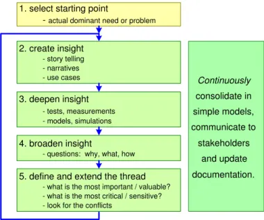
Figure 2.1 gives an overview of the iterative process of the threads of reasoning tech-nique. Step 1 is to select a starting pointfor the process. After step 1 the iteration starts with step 2create insight. Step 3 isdeepening the insightand step 4 is broaden-ing the insightvia suitable questions. Step 5defines and extends the thread. Moreover, the next iteration is prepared by step 5. In step 5, first the most important and critical threads are selected and one aims at finding conflicts. This insight and refinement might lead to selecting the next need or problem for the new iteration. During this iteration continuous effort is required tocommunicate with the stakeholders(the ones involved in the specific design decisions) to keep them up-to-date, and toconsolidate in simple models the essence of the problem, and to update the documentationto capture the insights obtained.
As mentioned before, the focus of threads of reasoning is to select the critical de-sign issues (step 5) that require in-depth studies to make a sound dede-sign trade-off. The in-depth studies are essentially step 3 in figure 2.1. The limited models for consolida-tion, communication and reasoningare derived from these possibly more complex and detailed models for analysis. Especially, since these in-depth studies require a major part of the design time, one has to be selective in the ones that are actually carried
2. create insight - story telling - narratives - use cases 3. deepen insight - tests, measurements - models, simulations 4. broaden insight
- questions: why, what, how 5. define and extend the thread
- what is the most important / valuable? - what is the most critical / sensitive? - look for the conflicts
1. select starting point
- actual dominant need or problem
Continuously consolidate in simple models, communicate to stakeholders and update documentation.
Figure 2.1:Overview of the threads of reasoning approach.
out. Of course, this does not mean that once the answers of these analyses have been obtained, the thread of reasoning is finished. On the contrary, it might actually be altered based on the findings or continued given these new pieces of information.
Below we will describe each of the individual steps in more detail. Moreover, we will present one thread of reasoning as an example from the case study to illustrate the steps.
Step 1: Select a starting point. A good starting point is to take a need or problem that is hot at the moment, within the problem scope. If this issue turns out to be important and critical then it needs to be addressed anyway. If it turns out to be not that important, then the outcome of the first iteration serves to diminish the worries in the organization, enabling it to focus on the really important issues. In practice there are many hot issues that after some iterations turn out to be non-issues. This is often caused by non-rational fears, uncertainty, doubt, ru-mors, lack of facts, etc. Going through the iteration, which includes fact finding, quickly clarifies the relevance of the issues.
2.3. The technique of threads of reasoning 19
many processing nodes should be used. Because of the size and the complexity of the software, which is both soft real-time and hard real-time for the various implemented functions, it is almost impossible to process all the code on one node, i.e. one processor. Nevertheless, there are various ways to distribute the software functionality over different (numbers of) nodes. There can be several ‘local nodes’ that handle separately the control of single motors. Another op-tion is to have only two big processing nodes that handle the entire paper flow control. This design issue is selected as the starting point of the thread. Step 2: Create insight. In this phase one wants to obtain a rough overview of and
insight in the chosen issue. The selected issue can be considered by means of one of the many (sub)methods to create more understanding. Typically, this can be done by the submethods story telling [58, Ch. 11], narratives [19] or scenario-based reasoning using e.g. use-cases [19]. Using these submethods, it will quickly become clear what is known (and can be consolidated and com-municated) and what is unknown, and what needs more study and hence forms input for the next step.
Example. To create some first insight into the problem of selecting the number and sizes of the processors in the control architecture, we linked this issue to the main design drivers section 2.2. For the time-to-market to be short, it is important to have a predictable development process. Therefore, a concur-rent design process is preferred, which is in favor of having multiple processing nodes. On the other hand, we also want the cost price to be low. Here, the ques-tion pops up how the cost price relates to the number of nodes. Looking at the design driver power consumption, there is an obvious relation that more nodes require more power, but more specific information is needed to reveal the exact relation and its importance.
Step 3: Deepening the insight. The insight is deepened by gathering specific facts. This can be done by modeling (and model-based analysis), or by tests and mea-surements on existing systems. Since the presented technique is iterative, in a first iteration one aims at using simple models, measurements or facts that are obtained in a reasonably short time. Typically, back-of-the-envelope cal-culations or rules of thumb that are known from previous projects are useful. In a second or subsequent iteration one selects the essential issues (most un-certain, most important) that require more modeling and analysis effort. This
aspect is coupled directly to the Boderc design methodology [39] based on multi-disciplinary modeling: to discover and select the in-depth modeling ac-tivities that have to be performed to support the system architect in taking (well-founded) design choices. In the design it is important to only spend time on the crucial issues and not on trivial ones to keep both the design effort and the time-to-market limited. Typically, the models are aimed at shedding light on the conflicts, which were identified earlier (step 5, first iteration).
Example. To get deeper insight in the issues of cost price and power us-age of processors, more specific information is needed. A rough quantitative estimate for the cost price showed that a node costs typically about 40 euros, of which 10 euros is calculated for the controller and 30 euros for the printed circuit board (PCB). Because for every node a separate PCB is used, doubling the number of processors roughly means doubling the cost price, although the cost price of the processor can be somewhat less for simple variants. Looking at power demands, it turned out that both the smaller and the bigger processors use about 3 Watt. It would therefore be beneficial to have as few processors as pos-sible. On the other hand, if we look at the power demands from other modules in the printer, that use up to 2 kW, we can assume that the power demand from the processors is of minor importance [27]. Therefore, the power issue will not be included in this thread of reasoning as we aim at describing only the most important aspects.
Step 4: Broadening the insight. Needs and problems are never nicely isolated from the context. Therefore, the insight is broadened by relating the need or problem to the other categories. This can be achieved by answeringwhy, whatandhow
questions. Examples: How can a main design driver be realized by sub drivers? How is a certain issue tackled? Why is a certain design choice good for a spe-cific design driver? What are the consequences of a design choice? How is the consequence related to a specific driver? The insight in the main design driver dimension can also be broadened by looking at the interaction with re-lated system qualities: what happens with safety or reliability when we increase the performance?
Example. What happens if all software would run on two processors? An issue that arises almost immediately from this question are possible syn-chronization difficulties. This is a typical aspect that needs to be considered in
2.3. The technique of threads of reasoning 21
further iterations. Other example questions for the case-study are: If we sepa-rate the software over multiple nodes, how efficiently can the software still be implemented? How would multiple processors be connected?
Step 5: Define and extend the thread. In the previous steps and corresponding dis-cussion of the needs, design choices and problems, many new issues popped up. A single problem can trigger an avalanche of new problems. Key in the approach is not to drown in this infinite ocean full of issues, by addressing the relevant aspects of the problem. This is done by evaluating the following as-pects:
1. Which specification and design decisions seem to be the most conflicting?
2. What is the value or the importance of the problem for the customer?
3. How difficult it is to solve the problem? It is important to realize that problems that can be solved in a trivial way should immediately be solved.
4. How critical is the implementation? The implementation can be critical because it is difficult to realize, or because the design is rather sensitive or rather vulnerable (for example, hard real-time systems with processor loads close to 70% or higher, due to which low priority tasks could be blocked for too long).
To evaluate the above aspects, the system architect often uses ‘gut-feeling’ based on many years of experience. Analysis techniques, such as Failure Mode Effects and Criticality Analysis (FMECA) can be used to analyze the impact of potential problems in the system in a more structured way. Typically, these techniques are used when the design is finished but they can be equally productive during other life-cycle phases of the design process. To compare various solutions, trade studies ([42], section 11.16) can effectively be applied as well.
The next crucial step is to define the thread. In this step theimportantrelations between the design drivers, design choices and consequences are represented in a concise diagram. Furthermore, the important conflicts should be clear from the diagram. The problem, that serves as the starting point for the next iteration, can be formulated in terms of this conflict. We believe that a clearly articulated problem is half of the solution.
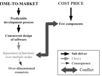
Figure 2.2:Example thread in the design of the paper flow control.
The insights obtained so far, in terms of the most crucial and critical conflicts, should help to select the new need or problem to go into the next iteration (back to step 2).
Example.At this moment in our reasoning on the number and size of pro-cessing nodes, the first thread becomes visible, as visualized in figure 2.2. The thread is structured by means of the framework of the categories as introduced before. The interpretation of this visualization is as follows:
• On the top of the picture, the relevantmain design driversare given in capitals,
• From the main design drivers,sub driversare derived, indicated in bold face,
• Specificdesign choicesthat satisfy the sub drivers, indicated in italic, • Theconsequencesthat come with specific choices, are depicted with small
dashed arrows,
• The mainconflicts, that are identified between any of the above mentioned aspects of the system, are depicted with thick double arrows.
Note that in step 3 we already concluded that the main design driver power should not be included in this thread. Hence, a step 5 action of discarding less relevant aspects of a thread was already applied. We see that from the question
2.4. Threads of reasoning for the case study 23
of how many processing nodes to use, a conflict arises between the drivers ‘time-to-market’ and ‘cost price’. As the most profound conflict is identified now, this can be input for step 2 and subsequently step 3. More detailed models (in com-parison with the simple estimates of cost price done earlier) would be useful to deepen the insight, which would support in making the trade-offs in the early design phase. From our first simple models we concluded that for reasons of cost price we want as few processing nodes as possible. However, a proper software design should still be feasible within a limited time span (influencing time-to-market). Therefore, we used a Parallel Object Oriented Specification Language (POOSL) model [62]. With this modeling language and analysis techniques, several possible architectures are evaluated and compared on their feasibility with respect to software timing requirements. Note that a part of the argumen-tation of a particular choice is captured now in the specific models made. In another setting (or a different architecture) this can be used to reevaluate the design choice. So some kind of “tracing” - as discussed in the introduction of this chapter - is kept.
The thread of reasoning of figure 2.2 was obtained by iterating one-and-a-half times through the 5-step scheme of figure 2.1. As we will see, this is typical for the case at hand as the aim of threads of reasoning in this setting is to select the in-depth models to be made. Normally more iterations - for instance, continuing after the modeling step - are used to find the essential conflicts.
2.4 Threads of reasoning for the case study
The structure that covers the most important threads and their relationships can be complicated for the design of complex systems, like a high-volume document printing system. In addition to the thread presented previously, we will describe two other essential threads in the control of the paper flow. In the presented figures we will use the same interpretation of the visualization as in figure 2.2.2.4.1 Stepper motors versus DC servo-motors
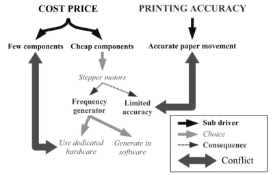
In this second example thread, the starting point is the use of stepper motors instead of the originally used DC servo-motors for driving the rollers in the printer paper path. The use of DC servo-motors is common for the printer manufacturer and less experience with stepper motors is present.
To create insight (step 2), the use of stepper motors was related to the identified main design drivers. It was easy to see that stepper motors relate to the cost price of the system, as the reason to select them in the first place was the fact that they are cheap. DC servo-motors are more expensive because of their need for (expensive) encoders and shorter lifetime. The use of stepper motors also relates to the printing accuracy. The accuracy of a stepper motor is limited because of various reasons, such as its mechanical construction, cogging and overshoot [28]. Because the stepper motors have to control the movement of the sheet, the sheet can only be controlled with limited accuracy. With a DC servo-motor (in combination with an encoder) the movement of the sheet can be controlled up to much higher accuracy and therefore is no issue.
To see whether the aspects discussed above are really important, we need to deepen our insight (step 3); in this case by quantifying the reasoning. The first aspect was the cost price. The average price of a (low power) stepper motor does not differ that much from the average cost price of a DC-motor. Both can be obtained (for large quantities) for typically less than 10 euros. For both types of motors an electrical driver is required, which also costs about the same for a stepper motor as for a DC-motor, i.e. circa 3 euros for low power applications. An encoder, which is solely needed to control the DC-motor, cannot be obtained below 20 euros for high resolution rotary encoders. This is one of the main reasons why the use of stepper motors is preferred.
Another aspect that needs some quantification is the accuracy of the stepper motor. First measurements reveal that this indeed is an important issue. Figure 2.3 shows a plot of position against time of a stepper motor running at 1 rotation/sec. Four steps are visualized of a 200 steps/revolution motor. The dashed line corresponds to the reference position, the solid line to the actual measured position. The horizontal grid lines indicate the size of the four steps that are visualized. Each step of the motor can be translated to a step-size in the order of 0.2 mm of the paper. From the figure it can be seen that the inaccuracy in the motors position is about 1 step size, i.e. 0.2 mm. As the printing accuracy is defined at 1 mm, the paper needs to be positioned with an accuracy well below 1 mm. The obtained value of 0.2 mm is therefore critical and needs to be evaluated further. It is nevertheless hard to quantify the impact on the real position of the sheet, because of load differences, the occurrence of slip and interactions between two motors that are controlling the same sheet of paper for some period of time. Therefore, more extensive models are needed.
calcula-2.4. Threads of reasoning for the case study 25 199.99 199.995 200 200.005 200.01 time(s) position reference position measured position
Figure 2.3:Measurement result of stepper motor.
tions that quantify the reasoning.
Like in the first example thread, we broaden our insight by means of the how, whatandwhyquestions (step 4). The first question could be how the motor should be controlled. The answer to this question is that a frequency generator needs to be imple-mented as for every step of the rotor, a drive pulse is needed. The follow-up question to this answer is how this frequency generator could be implemented. This pinpoints the question whether to do this with dedicated hardware or in software. Note that this question is a common struggle in industry nowadays. It comes down to the question whether cost price or accuracy and predictability is more important. Normally, hard-ware implementations are more reliable and faster or more accurate, but increase the cost price of the system.
The last step in this first iteration is the visualization of the thread. This is depicted in figure 2.4. We see that two important conflicts have been identified that need more attention. The first one is the use of dedicated hardware for the frequency generator in relation to the use of few components to reduce the cost price. The second conflict is identified between the limited accuracy of stepper motors and the requirements on the control accuracy of the sheets.
2.4.2 Time sliced versus event-driven architecture
During the design, a time sliced architecture was proposed for the processing nodes on which, for each node, multiple tasks are scheduled. The idea is that by assigning each task its own time slice, the execution of different functions is temporally separated and task interference is thus avoided. Therefore, software functions can be developed and tested separately while guaranteeing that it will work after combining them on
Figure 2.4:Thread of the example of stepper motors.
one processor if each task fits in a slice and there are enough slices. The fact that this choice also has some important disadvantages, makes it a good starting point for a new thread (step 1). To create insight (step 2), we again relate the issue to the main design drivers. The main reason for adapting the time sliced architecture is to shorten the time-to-market, as it enables predictable and composable software design. Further-more, we can use existing knowledge from past experience of the printer manufacturer (since the time sliced architecture has been applied in the past).
One of the disadvantages of using time slices is the inefficient use of available processing power. Because each task gets a pre-determined part of the available pro-cessor time, tasks cannot use the slack time of each other. To quantify the inefficiency of the time sliced scheduling in our case (step 3), we created a simple spread-sheet model which shows the tasks, the expected processor usage and the size of the slices. It also includes an estimation of the interrupts that can occur. Because the interrupts can interrupt any task, a task can effectively take longer to execute than its measured execution time (without interruption). To guarantee the composability of the system, we have to take this interrupt overhead into account for every slice. It turned out that the overhead of the interrupts in a time sliced approach is 20%, while if we replace the time sliced approach by e.g. an earliest deadline first scheduler [79], it becomes much less: 3%.
2.4. Threads of reasoning for the case study 27
Figure 2.5:Overview of several combined threads of reasoning.
choice of the time sliced architecture would be on the printing accuracy. From past experience, but also from literature it is known that the time sliced architecture intro-duces a limited action-reaction speed. As we need tight paper-image synchronization for accurate printing, this choice does influence the printing accuracy and therefore needs further in-depth investigation (via modeling).
Figure 2.5 visualizes this thread, together with the first two example threads. From the analysis above, a conflict is identified between the limited action-reaction speed, caused by the time sliced architecture, and the requirement of tight paper-image syn-chronization.
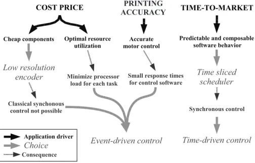
2.4.3 Total overview
The three example threads are visualized in figure 2.5 in one overview graph. It is interesting to see how these conflicts relate to each other. One example is found in the printing accuracy. The requirement of a high printing accuracy not only conflicts with the use of stepper motors, but also with the use of a time sliced architecture.
With the global overview we have obtained a clear list of conflicts where multi-disciplinary models can be made for deepening the insight (step 3). In figure 2.5, the
light grey boxes are added to indicate the models that have been made. These models give more insight into the identified conflicts. As mentioned before, the threads of rea-soning obtained here originate from one-and-a-half cycles through the 5-step scheme to end up with the in-depth models to be made. Although figure 2.5 originates from a limited set of starting issues, related to only a subsystem of the complete printer, and from only one-and-a-half iterations, it already shows a quite complicated structure. Nevertheless, the overview already captures the most important conflicts in the design of the control architecture for the paper path.
2.4.4 Detailed models to obtain insight in conflicts
To deepen the insight, specific models have been made, especially at design consid-erations where conflicts are identified. Figure 2.5 shows the objects of study of the models in the light gray boxes. To obtain more insight in the conflict explained in section 2.3 (the size and number of processing nodes), a POOSL (Parallel Object Ori-ented Specification Language) model is created [62]. With this modeling language and the analysis techniques, several possible architectures are evaluated and compared.
A second model was made in the language POOSL to analyze the processor load for the scenario in which the time sliced architecture is ‘polluted’ with interrupts, which are necessary to make optimal use of components. This is a more detailed model than the spread-sheet model described in section 2.4.2. Both models can also be used to see what the consequences are when the frequency generators for the stepper motors are implemented in software.
To optimally use the processors (and minimize the number of processors), a model was made to calculate optimal schedules for tasks in a time sliced architecture [7]. A stepper motor model, created in Matlab/Simulink, was used to analyze the positioning accuracy of stepper motors [28].
2.5 Conclusions
In this chapter, the technique of threads of reasoning was applied to identify the most important conflicts in the multi-disciplinary design of the paper flow control of the printer. This technique helps to structure in the typical chaos of uncertainty and the huge amount of realization options present in early design phases.
Threads of reasoning is one of the techniques used in the (Boderc) design method-ology that aims at using multi-disciplinary models to predict system performance in an
2.5. Conclusions 29
early design phase, while respecting the business constraints of available man power and time-to-market. The restriction in available design time (related to time-to-market and available man power) implies that in-depth and often time-consuming modeling and analysis should be performed only for the essential and critical issues. Threads of reasoning turns out to be - at least in the case of designing the control architecture for a printer - an effective means to find these issues and to create overview.
Combined with the in-depth models, threads of reasoning provides the system ar-chitect with valuable insight that supports him in making the important design trade-offs and to reduce some of the uncertainty in the early design phase. It results in a con-cise picture with the important conflicts depictedexplicitly. It forces the designer to quantify choices by replacing hand-waving with facts. This stimulates and focuses the discussion with the consequence of a shorter time-to-market and a more predictable design process. Moreover, a part of the argumentation of a particular design choice is captured now in the specific models made and techniques used.
It is a true observation that threads of reasoning itself does notcreateknowledge. It stimulates to make implicit knowledge explicit and indicates where knowledge is lacking and development time should be invested. In this line of reasoning, one could argue whether a technique like this is part of an engineering discipline. This does, nevertheless, not diminish the value of the technique.
Based on the case