6
Available online at www.ijiere.com
International Journal of Innovative and Emerging
Research in Engineering
e-ISSN: 2394 – 3343 p-ISSN: 2394 – 5494
REDUCTION OF VOLTAGE DISTURBANCES IN
DISTRIBUTION SYSTEM USING NEURAL CONTROLLER
Praveen. V and Dr. SNV Ganesh
Abstract:-
This paper describes the neural controller as analogous to PI controller for voltage regulation, performance of the DVR under different voltage disturbances. PI controller is difficult to tune for non linear systems; neural will be best choice for non linear systems. Dynamic Voltage Restorer (DVR) is series controller which has capability to mitigate the voltage disturbance by injecting missing voltage in series to the load. DVR comprises of inverter, DC energy storage and series transformer. The paper also presents modeling of DVR, and controller. Back-propagation concept is used for tuning an Artificial Neural Network controller as analogous to the PID controller to optimize the voltage regulation and load current disturbance. The performance of the neural based DVR is analyzed through different case studies. The circuit is simulated in matlab/simulink and results are presented to validate the proposed controller. Keywords: sag, swell, DVR, Neural controller
INTRODUCTION
Power quality has always dragged the attention of many researchers. Power quality may be defined as the ability of electrical network's or the grid's to supply a clean and stable power supply. Voltage distortions like power system harmonics and voltage are severe issue; affecting both the utility company and consumers in the same manner. Sensitive equipments are mostly affected by the nonlinear loads which create voltage and current harmonics [1–3].
Voltage sags can occur at any instant of time, with amplitudes ranging from 10 – 90% and a duration lasting for half a cycle to one minute [4]. Commercial power literally enables today’s modern world to function at its busy pace. Power system transmission lines are subjected to weather conditions such as hurricanes, lightning storms, snow, ice and flooding along with equipment failure, traffic accidents and major switching operations. In distribution systems, few causes of voltage disturbances are short circuit faults, lightning strokes, high starting currents of induction motors, and inrush currents [5]. Voltage disturbances are sags, swells and harmonics. Voltage sags can be symmetrical or unsymmetrical. Symmetrical sags have equal phase voltages and the 120 degrees phase relationship. Otherwise, the sag is unsymmetrical. Symmetrical sags are caused due to a three-phase short-circuit fault. Unsymmetrical sags are caused due to Single line-to-ground, phase-to-phase, or two phase-to-ground faults due to lightning, animals, accidents, and other causes, as well as energizing of large transformers.
These voltage disturbances can be minimized by series and shunt compensators. Dynamic Voltage Restorer (DVR) is a series compensator which is widely used; connected in series to load and source through a series injecting transformer. DVR minimizes the voltage disturbance by injecting missing voltage through voltage source converter driven by pwm pulses. However a good controller is required possessing qualities like dynamic response, stability and steady-state accuracy [7–14]. Few controllers have been presented earlier in literature studies, such as feedback and feed-forward [8], double-vector [9], proportional and integral (PI) [10], fuzzy and adaptive PI-fuzzy controllers [11, 12].
The rest of this paper organized as follows, section 2 presents the modeling of DVR. The concepts of neural controller are explained in section 3. Section 4 presents case studies in simulation results of DVR. Finally, the conclusion and discussion are given in section 5.
MODELING OF DVR
With the Thevinin model of the DVR as shown in the fig 1, the thevinin impedance is the resultant of fixed resistance, which is equivalent to losses in the DVR and fixed reactance, which is equivalent to reactive elements of the DVR. Modeling of DVR includes the voltage handling capability, current handling capability and size of energy storage. The voltage injection capability of DVR can be expressed as
𝑉𝐷𝑉𝑅% =
𝑉𝐷𝑉𝑅
7
DVR L th L th
V
V
Z I
V
(2)Fig 1: Thevenin model of DVR
The load current IL is given by
𝐼𝐿= (
𝑃𝐿+ 𝑗𝑄𝐿
𝑉𝐿
)
∗
The voltage injected by the DVR is
0
(
)
DVR L th th
V
V
Z
V
Where
,
and
are the angles of VDVR, Zth and Vth respectively. Ѳ is the load power factor angle and is given by𝜃 = 𝑡𝑎𝑛−1(𝑄𝐿
𝑃𝐿
)
From the eqn (2), assuming the thevinin impedance is very less (Zth << 1), the voltage injected by the DVR can be written as
𝑉𝐷𝑉𝑅= 𝑉𝐿− 𝑉𝑡ℎ= (1 − 𝐾)𝑉𝐿,
Where K indicates the ratio of source voltage to the load voltage
𝐾 =𝑉𝑡ℎ
𝑉𝐿
Apparent power required by the DVR (SDVR) is then calculated in terms of the apparent load power (SL).
𝑆𝐷𝑉𝑅= 𝑆𝐿(1 − 𝐾)
𝑆𝐷𝑉𝑅 = 𝑉𝐷𝑉𝑅𝐼𝐿∗
The corresponding active and reactive powers are:
𝑄𝐷𝑉𝑅 = 𝑆𝐿𝑠𝑖𝑛(𝜃𝐿) − |𝐾| sin(𝜃𝑠)
𝑃𝐷𝑉𝑅= 𝑆𝐿𝐶𝑜𝑠(𝜃𝐿) − |𝐾| Cos(𝜃𝑠)
Where Cos (ѲL ) and Cos (Ѳs) are the load power factor and source power factor.
cos
1
cos
th L
DVR L
L
V
P
P
8
NEURAL NETWORK ARCHITECTURE
Controller is the main component which dictates the system to follow the input. The main characteristics which controller shall possess are disturbance rejection and voltage regulation in case of DVR. The PI control has fails to accommodate all the conditions once parameters are fixed in the event of system parameters changes. Non-adaptability nature makes the tuning of PI very difficult sometimes. The intelligent techniques provide better solution due to quick adaptability nature. In this paper neural concept are used in dc voltage regulation. The controller input is the error signal obtained dc reference voltage and energy storage voltage. The error so obtained is processed by neural PI controller to generate Id current which is used to
generate reference signal.
The above proposed neural PI control algorithm can also be alternatively written as follows:
Step 1: Initially all the weights are set to small random value.
Step 2: Present an input vector P and a desired output O apply I to the input layer (m=0) so that Vo1
Step 3: For other layers, namely m=1…….M, forward computation is performed using the equation.
m m m 1i ij j
i
V
f
w v
Where
1 m m ij j
w v
= the connection weight from
1
m j
v
to
m ij
v
Step 4: The error is updated making use of the equation in step3 and fed to the layer
1
m m m m
i
v
iv
iO
iv
i
Step 5: Then back propagation errors for the proceeding layers M-1…..1 are calculated using the equation
1 1
1
1
m m m m m
i i i ji j
j
v
v
w
Step 6: Finally, all the weights are adjusted for next iteration and is given by the equation
1
1
m m m m
ij ij i j
w
t
w
t
v
Where
ɳ= gain parameter
Step 7: Repeat and go to step 2 until the desired epoch is achieved.
SIMULATION DIAGRAM AND RESULT
9 Fig 2: Simulation diagram for DG system with DVR under different fault conditions.
Table-1: System and DVR parameters
Case I: multiple Voltage sag created by three phase to ground fault for 2.5 cycles at different time periods. .
Fig 3: Load voltage depicting multiple sags
Discrete, Ts = 5e-005 s.
powergui
a b c
load1 A B C A B C A B C A B C a b c A B C a b c A B C a b c A B C a b c A B C A B C A B C A B C
A a B b C c
A B C Conn1 Conn3 Conn2 Conn5 Conn7 Conn8 Conn9 Conn4 Conn6 Vabcb1 Vabcb Vabca A B C a b c A B C a b c A B C a b c
0 0.05 0.1 0.15 0.2 0.25 0.3
-1 -0.8 -0.6 -0.4 -0.2 0 0.2 0.4 0.6 0.8 1 Time (secs) m ag ( pu )
Parameter value
Line resistance (Ω) 1.0
Line inductance (mH) 5.0
Line frequency (Hz) 50
Load phase voltage(V) 230
Load power per phase(W) 0.5HP
Injection transformer turns ratio 1:1
Saw-tooth carrier wave frequency (Hz) 2000
DC supply voltage (V) 400
Filter series inductance (mH) 20
Filter series resistance (Ω) 1
Filter shunt capacitance (µF) 20
10 Fig 4: Load voltage after DVR compensation
First sag occurs at 0.1 and lasts for 2.5 cycles and second sag occurs at 0.2 and last for 2.5 cycles. The voltage sag reduces the load voltage to 0.5pu without DVR. The fig 3 shows the load voltage with sag. The DVR is operated during the sag and the compensated load voltages are shown in fig4
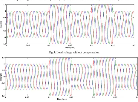
*Case II: Multiple voltage swells created by adding capacitive loads at various time periods in the system.
Fig 5: Load voltage without compensation
Fig 6: Load voltage after compensation
Fig 5 depicts the load voltage without compensation. The load voltage rises to 15pu which I very dangerous to the load. Swells are created at different time periods namely at 0.1 and 0.2, each lasting for 2.5 cycles. With DVR, the load voltage
0 0.05 0.1 0.15 0.2 0.25 0.3
-1 -0.8 -0.6 -0.4 -0.2 0 0.2 0.4 0.6 0.8 1
Time (secs)
M
ag
(
pu
)
0 0.05 0.1 0.15 0.2 0.25 0.3
-1.5 -1 -0.5 0 0.5 1 1.5
Time (secs)
m
a
g
(
p
u
)
0 0.05 0.1 0.15 0.2 0.25 0.3
-1.5 -1 -0.5 0 0.5 1 1.5
Time (secs)
m
a
g
(
p
u
11 comes to normal voltage; during swell conditions, the DVR injects voltage at 180deg out of phase to bring load voltage to normal. Fig 6 shows the load voltage after compensation.
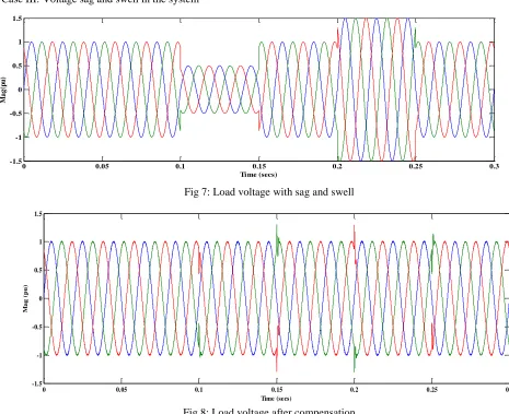
* Case III: Voltage sag and swell in the system
Fig 7: Load voltage with sag and swell
Fig 8: Load voltage after compensation
Fig 7 &8 depicts the load voltages without and with compensation. DVR is able to compensate sags, swell at the load very quickly. Although there exits little transient during starting and ending of operation of DVR; but for very small time which does not affect the load.
CONCLUSIONS
In this paper voltage sag/swell compensation and elimination of fault using Dynamic Voltage Restorer is considered. The control technique is designed using in-phase compensation and used a closed loop control system to detect the magnitude error between voltages during pre-sag and sag periods. The modeling and simulation of closed loop control of voltage sag/swell mitigation were carried out using MATLAB software. DVR with neural network controller is able to effectively mitigate these disturbances and make the load voltage maintain constant. The results indicate that neural is better controller in mitigating voltage disturbances very fast.
REFERENCES
[1] Jayaprakash P, Member, Singh B, Kothari D P, Chandra A, Al-Haddad K, “Control of Reduced-Rating Dynamic Voltage Restorer with a Battery Energy Storage System” at IEEE TRANSACTIONS ON INDUSTRY APPLICATIONS, VOL.50, and Issue 2, MARCH/APRIL 2014, pp-1295-1303
[2] Choi S S, Wang T X and Vilathgamuwa D M, “A series compensator with fault current limiting function,” IEEE Transactions on Power Delivery volume 20, no.3, pp.2248–2256, Jul.2005.
[3] Deliveryfino B, Fornari F, and Procopio R, “An effective SSC control scheme for voltage sag compensation,” IEEE Transactions .Power Delivery. vol.20, no.3, pp.2100–2107, Jul.2005.
0 0.05 0.1 0.15 0.2 0.25 0.3
-1.5 -1 -0.5 0 0.5 1 1.5
Time (secs)
M
a
g
(p
u
)
0 0.05 0.1 0.15 0.2 0.25 0.3
-1.5 -1 -0.5 0 0.5 1 1.5
Time (secs)
M
ag
(p
u
12 [4] Badrkhani F Ajaei, Afsharnia S, Kahrobaeian A, and Farhangi S, “A fast and effective control scheme for the dynamic
voltage restorer,” IEEE Transactions. Power Delivery, vol.26, no.4, pp.2398–2406, Oct.2011.
[5] Roncero Sánchez, Acha E, Ortega Calderon J E, Feliu V, and García A, “A versatile control scheme for a dynamic voltage re-storer for power-quality improvement,” IEEE Transactions. Power Delivery, vol.24, no.1, pp.277–
[6] Weixing, Ooi B T, "Optimal Acquisition and Aggregation of Offshore wind Power by Multiterminal Voltage-Source HVDC," IEEE Transactions. Power Delivery, vol.18, pp.201–206.
[7] Boonchiam P and Mithulananthan N, “Understanding of Dynamic Voltage Restorers through MATLAB Simulation,” Thammast Int.J.Sc.Tech., Vol.11, No.3.
[8] Vilathgamuwa D M, Perera M A A D R, and Choi S S, “Performance improvement of the dynamic voltage restorer with closed-loop load voltage and current-mode control,” IEEE Transactions.Power.Electron.vol.17, no.5, pp.824–834. [9] Weimers, L."A New Technology for a Better Environment," Power Engineering Review, IEEE, vol.18, issue 8, PP
1560-1563.
[10] Schettler F., Huang H., and Christl N."HVDC Transmission systems using voltage source converters – design and applications," IEEE Power Engineering Society Summer Meeting, July 2000, pp 715-720.
[11] Jeong J, Han B “Development of Line-Interactive Dynamic Voltage Restorer with Hybrid Sag Detection” IEEE Transactions, Volume 3 July 2010.
[12] Bae B, Jeong J “Novel Sag Detection Method for Line-Interactive Dynamic Voltage Restorer” IEEE Transactions on power Delivery, vol.25, Issue 2, April 2010 pp-1210-1211.
[13] K. A. Siddartha, N. Manikanta Babu, Y. Suresh, M. Varun Mohan “Enhanced Performance of a DVR using Mixed Cascaded Multilevel Inverter” INDJST Journal, Volume 8, Supplementary 2, January 2015”.
[14] D. Deepak Chowdary, G. V. Nagesh Kumar “Restoration of Single Phase Distribution System Voltage under Fault Conditions with DVR Using Sliding Mode Control” INDJST Journal, Volume 1, Issue 5, October 2008.