International Journal of Engineering
J o u r n a l H o m e p a g e : w w w . i j e . i rEffect of Length-scale Parameter on Pull-in Voltage and Natural Frequency of a
Micro-plate
K. Rashvand, G. Rezazadeh*, H. Madinei
Mechanical Engineering Department, Urmia University, Urmia, Iran
P A P E R I N F O
Paper history:
Received 27 July 2013
Received in revised form 05 September 2013 Accepted 14 September 2013
Keywords:
Material Length-Scale Parameter Modified Couple Stress Theory Rectangular Micro-plate Stability
A B S T R A C T
This paper deals with the effect of the intrinsic material length-scale parameter on the stability and natural frequency of a rectangular micro-plate for two different cases; fully clamped and fully simply supported. A variation formulation based on Hamilton’s principle and the modified couple stress theory is used to obtain the nonlinear governing equation of a micro-plate incorporating the stretching effect. In the static case, the nonlinear governing equation is solved using the step-by-step linearization method (SSLM) and in the dynamic case, is integrated using fourth-ordered Runge-Kutta method. The static and dynamic pull-in parameters, limiting the stability regions of capacitive MEMS devices, are calculated and compared to those obtained by the classical theory. The numerical results reveal that the intrinsic size dependence of materials is more significant for smaller thicknesses and in this case, the stretching effect can be neglected.
doi:10.5829/idosi.ije.2014.27.03c.04
1. INTRODUCTION1
Micro-electro-mechanical-systems (MEMS) technology has been quickly growing since its beginning in 1980s as sensors and actuators. Their light weight, small size and low-energy consumption made them even more attractive. Mechanical resonators have been widely used as transducers in mechanical micro-sensors. RF MEMS refers to the application of MEMS technology to high frequency circuits (radio frequency (RF), microwave, or millimeter wave) in telecommunications, radar systems and personal mobiles.
Electrostatic actuation of conductive flexible beams/plates due to their simplicity, as they require few mechanical components and small voltage levels for actuation are mostly used in many fields [1-3].
Electrically actuated beams/plates are influenced to instability, which is known as pull-in phenomenon in MEMS literature. In pull in voltage the elastic restoring force can no longer resist the opposing electrostatic force, thereby leading to the collapse and failure of the structure [4, 5]. Thus, pull in instability is a major structural safety concern for MEMS structural design.
1*Corresponding Author Email: [email protected] (G. Rezazadeh)
For its importance in MEMS structural safety, pull in instability has been investigated by several researchers [6-8].
Experimental results have been revealed that the behaviors of micro-scale structures are size dependent [9].Therefore, the classical theory (CT) is not capable to predict their behaviors properly. During past years, some non-classical theories such as couple stress theory have been introduced, developed and employed to accurately predict the mechanical behavior of micro-scaled structures. Yang et al. [10] modified the classical couple stress theory [11] based on an additional equilibrium relation to predict the behavior of the couples. According to the Cosserat (micro-polar) theory of elasticity [11, 12], there is a torque per unit area, or couple stress, as well as the usual force per unit area, or stress in classical elasticity.
static instability and natural frequency of an electro-statically actuated Kirchhoff micro-plate using CT.
MCT has been developed for the static bending and free vibration problems of a simply supported Timoshenko beam [14], the static bending problem of a cantilever Bernoulli-Euler beam [15], and free vibration of two boundary value problems, one for a simply supported and another for a cantilever Bernoulli-Euler beam [16] so far. In the mentioned works, majorly, the static model of micro beams and micro-plates are considered. It is decided to model the static and dynamic response of micro-plates based on MCT.
In a prior related study [17], an isotropic rectangular micro-plate was studied statically via MCT without considering the effect of the axial stress generated by the mid-plane stretching of the micro-plate.
In this work, a Kirchhoff plate model is derived for the dynamic analysis of a rectangular micro-plate using MCT considering stretching effect. To this end, Hamilton’s principle is applied and the results are presented for two different boundary conditions. The time histories and phase trajectories of the micro-plate response to a step DC voltage are given. Including the length-scale parameter, the static and dynamic pull-in voltages of the micro-plate are calculated for different thicknesses and compared to the results obtained from CT.
2. MATHEMATICAL MODEL
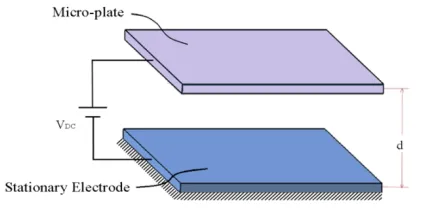
Electrically actuated micro-plates are the main component in micropumps, microphones and many micro-sensors [18, 19]. A schematic view of a capacitive rectangular micro-plate suspended over a stationary conductive plate as a RF MEMS device with lengtha, widthb , gapd , uniform thicknessh, densityr , shear modulusG and Young’s modulus E is illustrated in Figure 1. The movable rectangular micro-plate is modeled using Kirchhoff plate theory. When a voltage is applied to these plates, the movable micro-plate is deflected under the effect of the distributed transverse electrostatic load toward the stationary electrode [20]. The space between the plates (gap) is filled with a dielectric like air.
According to MCT [9, 10], the strain energy density in an isotropic linearly elastic material occupying a volume V bounded by the surfaceΩis given as
(
)
1
,
2 s e c
=
ò
ij ij + ij ijV
U m dV (1)
where, sij is the Cauchy (classical) stress tensor, mijis
the deviatoric part of the couple stress tensor and [9]
(
, ,)
1 ,
2
eij = ui j +uj i (2)
Figure 1. Schematic 3D view of the rectangular electrostatically actuated micro-plate
and
(
, ,)
1 ,
2
cij = qi j+qj i (3)
are the strain tensor and the symmetric part of the curvature tensor, respectively. ui is the displacement
vector and qiis the rotation vector defined as [10]
,
2 ,
1
qi = e uijk k j (4)
in which, eijkis the permutation symbol. The
constitutive equations are [10]
2 ,
sij =le dkk ij + meij (5)
2 2m c ,
=
ij ij
m l (6)
where,l andm are Lamé ’s constants,dijis the
Kronecker delta andl is a material length-scale parameter measuring the couple stress effect.
In a Cartesian coordinate system, where the xy
-plane is coincident with the geometrical mid--plane of the un-deformed plate, the relationship between the displacement components u x y z t( , , , ), v x y z t( , , , )
and w x y z t
(
, , ,)
along the x , y and z directions, respectively, based on Kirchhoff thin plate theory can be expressed as [21](
)
(
)
(
)
(
)
(
)
(
)
, ,
, , , ,
, ,
, , , ,
, , , , , .
w x y t
u x y z t z
x w x y t
v x y z t z
y
w x y z t w x y t
¶ =
-¶ ¶ =
-¶ =
(7)
Considering the mid-plane displacements, the nonlinear strain components are stated as [22]
2 2
1 1 1
.
, ,
2 2 2
e = çæ¶ ö÷ e = æç¶ ö÷ e = ¶ 
¶ ¶ ¶ 
è ø è ø
s s s
xx yy xy
w w w w
x y x y (8)
stress (Equation (5)) and couple stress tensors (Equation (6)), the bending moments including the components of the classic stress tensor [21] are obtained as follow
(
)
/2 2 2
2 2
/2
/2 2 2
2 2 /2 /2 2 /2 , , 1 , h xx xx h h yy yy h h xy xy h w w
M zdz D
x y
w w
M zdz D
y x
w
M zdz D
x y s s s s n s n s n
-æ¶ ¶ ö
= = - ç¶ + ¶ ÷
è ø
æ¶ ¶ ö
= = - ç¶ + ¶ ÷
è ø ¶ = = - -¶ -
ò
ò
ò
(9)and those bending moments including the components of the couple stress tensor are
/ 2 2
/ 2
/ 2 2
/ 2
/ 2 2 2
2 2 / 2 2 , 2 , , h m l xx xx h h m l yy yy h h m l xy xy h w
M m dz D
x y w
M m dz D
x y
w w
M m dz D
y x -¶ = = ¶ ¶ ¶ = = -¶ -
æ¶ ¶ ö
= = ç¶ -¶ ÷
è ø
ò
ò
ò
(10) where,(
)
3 2 , 12 1 Eh D n = - (11)is the bending rigidity of the plate and
(
)
2
2 ,
2 1
l El h
D l Gh
n
= =
+ (12)
is the contribution of rotation gradients to the bending rigidity. The ratio of the total rigidity D D+ l over the
bending rigidity is
( ) 22
1 1 6 1 .
l l
D D D l
D D n h
+
= + = + - (13)
According to Hamilton’s principle, the actual motion minimizes the difference of the kinetic energy and total potential energy for a system with prescribed configurations at t =0and T [23]. That is,
(
)
0
0. T
K U W dt
d
ò
éë - - ùû = (14)The first variations of the kinetic energy of the plate is given by
2
2
0 0Ω
Ω .
d = - r ¶ d
ò
òò
T T
w
K d t h w d d t
t (15)
The variation of the strain energy of the micro-plate considering the strain energy due to mid-plane displacement on the time interval [0, ] T is obtained as
/ 2
/2 0 0Ω
2
d Ω ,
2 2
xx xx yy yy
h
T T
xy xy xx xx
h
yy yy xy xy
s s s
xx xx yy yy xy xy
σ δε σ δε
σ δε m δχ dz
δ U t d dt
m δχ m δχ
N δε N δε N δε
-é æ + + ö ù
ê ç ÷ ú
+
ê ç ÷ ú
= ê çç + ÷÷ ú
ê è ø ú
ê+ + + ú
ê ú
ë û
+
ò
ò
òò
(16)where,
(
Nxx,Nyy,Nxy)
are the mid-plane forces per unitlength, which are given as
( ) 2 2 2 0 0 2 2 2 0 0 0 0 1 1 ,
1 2 2
1 1
,
1 2 2
1
, 2 1 2
a b s xx xx b a s yy yy b a s xy xy
Eh w w
N σ h dx ν dy
ν a x b y
Eh w w
N σ h dy ν dx
ν b y a x
Eh w w
N σ h dxdy
ν ab x y
æ æ¶ ö æ¶ ö ö
ç ÷
= = - ç çè¶ ÷ø + ç¶ ÷ ÷
è ø
è ø
æ æ¶ ö æ¶ ö ö
ç ÷
= = - ç ç¶ ÷ + çè¶ ÷ø ÷
è ø
è ø
æ æ¶ öæ¶ ö ö = = + çç çè¶ ÷ç¶ ÷ ÷÷
øè ø è ø
ò
ò
ò
ò
òò
(17)in which
(
s , s , s)
xx yy xyσ σ σ are the stretching stresses. The first variation of the work, which is done by a distributed loading q x y
(
,)
on the time interval [0, ] T , is0 0Ω
Ω .
=
ò
ò ò
T T
δ W d t qδw d d t (18)
Substitution of Equations (9), (10), (15), (16) and (18) into Equation (14) and after some mathematical manipulations, yields the following differential equation governing transverse motion of a rectangular micro-plate
2 2
2
2 2
2 2 2
2
2 2
2 2 2 2
2 2 2
2 2 . σ σ σ yy xy xx
m m m
m
yy xy xy
xx
xx xy yy
M M
M
x y
x y
M M M
M
x y x y x y
w w w w
N N N q ρh
x y
x y t
¶ ¶ ¶ + + -¶ -¶ ¶ ¶ ¶ ¶ ¶ ¶ + + - + ¶ ¶ ¶ ¶ ¶ ¶ ¶ + ¶ + ¶ + = ¶ ¶ ¶ ¶ ¶ ¶ (19)
The governing equation of the micro-plate in terms of the deflection is obtained by substitution of Equations (9) and (10) into Equation (19) as
(
)
2 24 2 2 2 2 2 2 , l xx xy yy w w
D D w N N
x y x
w w
N ρh q
y t
¶ 
+ Ñ - -
-¶ -¶ 
¶ + ¶ =
¶ 
(20)
where,Ñ4is the biharmonic operator in the Cartesian coordinate system.
According to Figure 1, it is assumed that the potential of the micro-plates is imposed by a voltage supply. The energy stored Weby a parallel plate capacitor C and applied voltage V across its terminals is given by
2 2 1 1 , 2 2 e k abV W CV d e
= - = - (21)
where, dis the separation distance between the plates (gap), k the dielectric constant (for air it is assumed
1
k = ), ande the permittivity of free space (for air
0
yields the electrostatic force between the plates due to the applied voltage
2 0 2 d 1 . d 2 e e W abV F d d e
= = (22)
This equation states that the force versus separation distance and the force versus voltage relationships are nonlinear. It must be noted that in the dynamic case phase delay in voltage propagation on the plate is possible. Consequently, the dynamic pull-in voltage, switching time and other dynamic characteristics of such a plate resonator may be affected. This effect is quite less appearing in usual MEM devices unless the resistance is intentionally designed to be high [24]. Therefore, Equation (21) can be used for the dynamic case as well as for the static case. Definingq w V( , )as the electrostatic nonlinear pressure of the micro-plate, Equation (22) be expressed as [13]
(
)
(
)
(
)
2 0 2 0 , , 2 , e F Vq w V
ab g w x y
e
= =
- (23)
where, g0is the initial gap between the movable and fixed or ground plates (d =g0-w ).
The boundary conditions for a rectangular micro-plate with all edges clamped (CCCC) are
0, 0, ¶ = = ¶ ¶ = = ¶ w w x w w y at at 0, , 0, , = = x a y b (24)
and those for the case with all edges simply supported (SSSS) are 2 2 2 2 0, 0, ¶ = = ¶ ¶ = = ¶ w w x w w y at at 0, , 0, . = = x a
y b (25)
For convenience, the following dimensionless parameters are defined to transform Equations (20) and (23) into non-dimensional forms
0
4
ˆ ,ˆ , ˆ ,ˆ * .
*, r
=w =x =y = t = a
w x y t
a a h t t D g (26)
Substitution of Equations (13), (23) and (26) into Equation (20) yields the following non-dimensional deflection equation
(
)
2 2
4 4 4 2
4 4 2
2 2 2 2
2 2 2
ˆ ˆ ˆ ˆ ˆ
2
ˆ ˆ ˆ ˆ ˆ
ˆ ˆ ˆ
ˆ ˆ
2 ˆ ,
ˆ ˆ ˆ 1 ˆ
l
xx
xy yy
D D w w w w
N
D x x y y x
w w w V
N N
x y y t a w
æ ö
+ ¶ + ¶ +¶ - 
-ç¶ ¶ ¶ ¶ ÷ 
è ø ¶ - ¶ +¶ = ¶ ¶ ¶ ¶ -(27) where, 4 03 0 , 2 e a= g a D
(
)
2 2 2 0 0 0 2 2 2 0 0 0 2 0 0 0 ˆ ˆˆ 6 ˆ ˆ ,
ˆ ˆ
ˆ ˆ
ˆ 6 ˆ ˆ ,
ˆ ˆ
ˆ ˆ
ˆ 3 1 ˆ ˆ
ˆ ˆ
b a 1
xx
b a 1
yy
b a 1
xy
g w a w
N dx ν dy
h x b y
g a w w
N dy ν dx
h b y x
g a w w
N ν dxdy
h b x y
æ æ¶ ö æ¶ ö ö
æ ö ç ÷
= çè ÷ çø çè¶ ÷ø + ç¶ ÷ ÷
ç è ø ÷
è ø
æ æ¶ ö ¶ ö
æ ö
æ ö ç ÷
= ç ÷ ç ç ÷ + ç ÷ ÷
¶ 
è ø çè è ø è ø ÷ø
æ æ ö
¶ 
æ ö
æ ö
= - ç ÷ ç¶ ÷ç¶ ÷
è ø è è øè ø
ò
ò
ò
ò
ò ò
.ö
ç ÷
ç ÷
ç ÷ø
(28)
3. NUMERICAL APPROACH
3. 1. Static Analysis In order to solve the static equation, step-by-step linearization method (SSLM) is employed similarly to Talebian et al. [13] and Rashvand et al. [17]. Then, the static deflections of the micro-plate due to the applied voltages are obtained.
3. 2. Dynamic Analysis Due to the nonlinear nature
of Equation (27), creating a Galerkin based reduced-order model is complicated. Hence, the existing nonlinear term is considered as a forcing term and the integration of this term is repeated at each time step over the micro-plate domain.
The dynamic response of the micro-plate is approximated with linear combinations of a finite number of suitable shape functions with time dependent coefficients as follow
(
)
( )
( ) ( )
n 1 m 1
N M
mn m n
ˆ
ˆ ˆ ˆ
w x, y, t q t f xˆ j yˆ .
= =
=
åå
(29)Substituting Equation (29) into Equation (27) and multiplying by fm
( ) ( )
xˆ jn yˆ as a weight of Galerkin’s method and integrating the outcome in non-dimensional domain yield the reduced-order model. The response of the micro-plate to a step DC voltage can be calculated by integrating the ordinary-differential equation of the reduced-order model over time as(
)
1 1 1 1
, s
klmn klmn klmn
n m n m
N M N M
e
mn mn kl
M q K K q F
= = = =
+ - =
åå
&&åå
1, 2,..., , 1, 2,...,
= =
k M l N
(30)
where 1 1
0 0
k lm n k l m n
1 1 4
4 0 0
1 1 2 2
2 2
0 0
1 1 4
4 0 0
2 ,
m
k l n
l
m n
klmn k l
n k l m
φ φ dxdy
x
φ
D D
K φ dxdy
D x y
φ
φ dxdy
y
f f
f f
f f
æ ¶ + ö
ç ¶ ÷
ç ÷
ç ¶ ¶ ÷
+ ç ÷
= +
ç ¶ ¶ ÷
ç ÷
ç ÷
ç ¶ ÷
è ø
òò
òò
òò
1 10 0
1 1 1 1
2 0 0
2
0 2
2
0
2
s m
klmn k l n
m n n
k l k l m
K φ φdxdy
x
φ φ
φ dxdy φ dxdy,
x y y
f f
f
f f f
= +
¶ ¶ 
+
¶ ¶ 
òò
òò
òò
(
)
1 1
2 0 0
2
1 mn
e
kl k l
m n
αV
F φ dxdy.
q φ
f
f
=
-òò
Calculating qmnin Equation (30), then substituting back into Equation (29) to computew x y t
(
ˆ ˆ, ,ˆ)
.4. RESULTS AND DISCUSSIONS
The following admissible shape functions, are used for CCCC
( ) ( )
m n
2 ˆ 2 ˆ
sin (m x)sin (n y
ˆ )
ˆx y ,
f j = p p (32)
and for SSSS
( ) ( )
m xˆ n yˆ sin(m x)sin(n yˆ ˆ).
f j = p p (33)
In order to verify the numerical results of CCCC boundary conditions, the static pull-in voltage of a micro-plate with the same geometry and properties of that studied by Talebian et al. [13] is obtained and compared with experimental results of Francais and Dufour [25]. As illustrated in Figure 2, by plotting non-dimensional center gap (1-wˆ ) versus non-dimensional voltage, the results are in good agreement with each other.
Figure 2. Comparison of computed non-dimensional pull-in voltage with the experimental results [26] for the CCCC micro-plate
To verify the numerical results of SSSS boundary conditions, the natural frequency is obtained and compared with the analytical fundamental frequency obtained by Reddy [26]. The obtained natural frequency (2.59 MHz for a given voltage 0V) was found to be in good agreement with the analytical one presented by Reddy (2.51 MHz) [26].
One of the purposes of this work is to study the effect of the length-scale parameter on the response of the micro-plate and compare the differences between the results obtained from the classical and modified couple stress theories. However, silicon has a small material length-scale parameter and the differences between the results of these theories are not considerable. Therefore, we used gold properties instead of silicon.
Table 1 shows length-scale values of gold [27] for different thicknesses. As shown in Table 1, these values are considerable in comparison to the thickness. The material [28] and geometrical properties of the considered micro-plate are listed in Table 2.
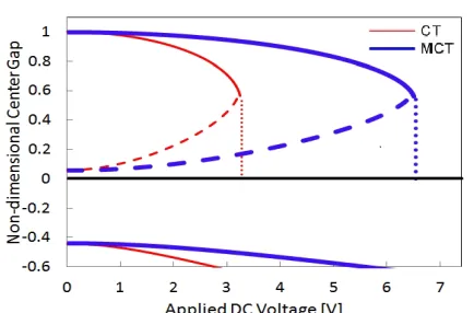
Figures 3 and 4 show non-dimensional center gap ( ˆ
1-w ) versus the applied DC voltage in which the positions of the stable centers and unstable saddle are pointed by solid and dashed curves, respectively. As shown in Figures 3 and 4, applying MCT shifts the saddle-node bifurcation point to the right, and consequently the value of the calculated pull-in voltage increases. These calculated pull-in voltages are brought in Table 3.
TABLE 1. Material length-scale of gold [27] Thickness of Au (mm) Length-scale parameter (mm)
0.5 0.47
1 0.73
2 1.05
TABLE 2. Material [28] and geometrical properties of the micro-plate
Symbol Quantity Value
a length 250mm
b width 250mm
h thickness 0.5mm
E Young’s modulus 79GPa
n Poisson’s ratio 0.43
r density 19300kg m3
0
e permittivity of air 8.8541878*10-12F m
0
Figure 3. Equilibrium-Positions of the CCCC micro-plate versus applied voltages based on CT (red lines) and MCT (blue lines)
Figure 4. Equilibrium-Positions of the SSSS micro-plate versus applied voltages based on CT (red lines) and MCT (blue lines)
Figure 5. Variation of the non-dimensional fundamental frequency of the CCCC micro-plate versus applied DC voltages
As seen in Figure 3, similar to the results of lumped model of the CCCC micro-plate [17], for a given applied voltage (0<V V< pull in- ) three fixed points exist. The first is a stable center, the second is a unstable
saddle node and the third is a mathematically stable center but physically impossible. For V V> pull in- it decreases to a mathematical stable center. However, it is physically impossible. The impossibility of the third stable solution refers to the existence of the substrate beneath, which restricts the amplitude of the micro-plate motion.
The variation of the non-dimensional fundamental frequency of the micro-plate versus the applied DC voltage from zero to the pull-in voltage for CCCC and SSSS are depicted in Figures 5 and 6. As shown, the values of the fundamental frequency, for a typical micro-plate thickness obtained by MCT are greater than those obtained by CT for both types of boundary conditions. The experimental results obtained by Ballestra et al. [29] and the numerical results obtained by Jomehzadeh et al. [30] confirm this realistic trend.
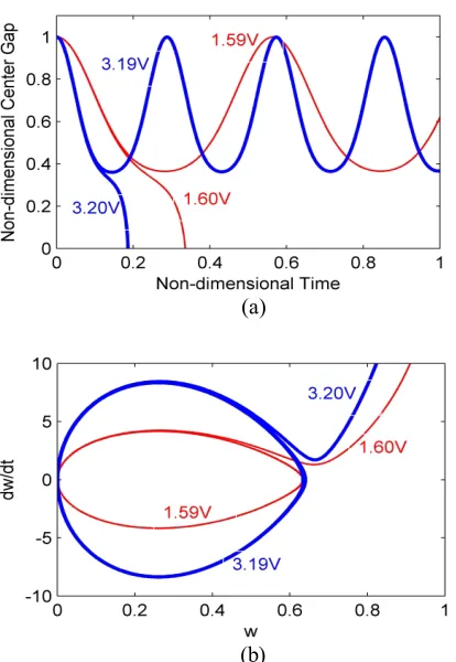
The dynamic responses and phase portraits of the micro-plate for zero initial conditions and different step DC voltages based on CT and MCT for CCCC and SSSS boundary conditions are plotted in Figures 7 and 8, respectively.
Figure 6. Variation of the non-dimensional fundamental frequency of the SSSS micro-plate versus applied DC voltages
(b)
Figure 7. The CCCC micro-plate based on CT (red lines) and MCT (blue lines) to different step DC voltages, a) Dynamic response, b) Phase portrait
(a)
(b)
Figure 8. The SSSS micro-plate based on CT (red lines) and MCT (blue lines) to different step DC voltages, a) Dynamic response, b) Phase portrait
TABLE3.Values of Static and Dynamic Pull-in Voltages (V) and Natural Frequencies (kHz)
CCCC SSSS
CT MCT CT MCT
Static pull-in 3.27 6.54 1.77 3.54
Dynamic pull-in 2.95 5.91 1.60 3.20
Natural frequency 192.62 386.30 102.15 204.87
As illustrated in these figures, the system becomes unstable for some step DC voltages smaller than the value of the static pull-in voltage through a homoclinic bifurcation. This phenomenon is called dynamic pull-in in MEMS literature, the critical (minimum) step DC voltage, in which the dynamic pull-in phenomenon happens, is called dynamic pull-in voltage. The dynamic pull-in voltages are about 92% of the static pull-in voltages [31], which is consistent with the results presented here (Table 3). Table 3 shows the numerical comparison of mechanical behavior predicted by CT and MCT. Figure 9 shows the effect of the stretching stress on the static pull-in voltage for a range of sufficiently large values of gap for CCCC boundary condition based on CT and MCT. As shown in Figure 9, the stretching effect is negligible for small gaps, while it is significant for bigger gaps. Figure 10 shows the ratio of the dynamic pull-in voltage calculated by MCT to the one calculated by CT (VM CT VCT ) versus thickness. These results obtained with fix value of length scale for all thicknesses [32] and compared with the experimental results which are accessible in three thicknesses according to Table 1 [27] for CCCC micro-plate.
Figure 9. Effect of the stretching stress on the static pull-in voltage for the CCCC micro-plate based on CTs (red line) and MCTs (blue line) in comparison of CT (red dashed) and MCT (blue dashed) ignoring stretching effect
(b)
Figure 10. Dynamic pull-in voltage ratio versus thickness of the micro-plate with l=1.12mm[32], a) for the CCCC micro-plate and compared with experimental l in three thicknesses (Table 1), b) for the SSSS micro-plate
As can be seen in Figure 10, for smaller values of the thickness, the difference between the results obtained from the two theories is significant. Of course, for larger values of the thickness, the dynamic pull-in ratio approaches to 1. It means that the results obtained based on MCT are similar to the results obtained from CT.
As experimental results for the CCCC boundary conditions for some thickness values are available, hence for this case comparison of the numerical results obtained by MCT and CT with the experimental one is capable. As shown in Figure 10.a, the results of MCT for thicknesses about 1 2- mm with fix value of the length-scale [32] are in agreement with the experimental results of the certain thicknesses [27].
5. CONCLUDING REMARKS
In this paper, a rectangular micro-plate was modeled based on the modified couple stress theory, considering the stretching effect. From a detailed variational procedure, the governing equation of the micro-plate was derived in terms of the deflection using the Hamilton’s principle. The obtained equation was solved utilizing the step-by step linearization method and applying the Galerkin based weighted residual method, and the pull-in voltages were calculated based on MCT and CT.
It was found out that in the case of gradually application of the voltage, the micro-plate goes towards an unstable condition through a local saddle node bifurcation, while in the case of applying a step DC voltage, the micro-plate experiences an instability through a global homoclinic bifurcation. In the similar
properties, the pull-in voltages and the natural frequencies of the CCCC micro-plate are larger because of a larger stiffness than those of the SSSS micro-plate.
Based on the numerical results, it is concluded that for the micro-plate, the effect of material length-scale is significant as the thickness becomes smaller, and the MCT results are closer to the experimental ones than those obtained by CT. In addition, it was showed that the stretching effect is negligible for small gaps, while it is significant for bigger gaps. The obtained results are useful for the MEMS community in the accurate design of MEMS devices.
6. ACKNOWLEDGEMENT
The authors are grateful for the critical and helpful comments of the anonymous referees.
7. REFERENCES
1. Rezazadeh, G. and Moradi-Tahmasebi, A., "Electromechanical behavior of microbeams with piezoelectric and electrostatic actuation", Sensing and Imaging: An International Journal, Vol. 10, No. 1-2, (2009), 15-30.
2. Rezazadeh, G., Fathalilou, M., Shabani, R., Tarverdilou, S. and Talebian, S., "Dynamic characteristics and forced response of an electrostatically-actuated microbeam subjected to fluid loading",
Microsystem Technologies, Vol. 15, No. 9, (2009), 1355-1363. 3. Vahdat, A. S. and Rezazadeh, G., "Effects of axial and residual
stresses on thermoelastic damping in capacitive micro-beam resonators", Journal of the Franklin Institute, Vol. 348, No. 4, (2011), 622-639.
4. Rezazadeh, G., Tahmasebi, A. and Ziaei-rad, S., "Nonlinear electrostatic behavior for two elastic parallel fixed–fixed and cantilever microbeams", Mechatronics, Vol. 19, No. 6, (2009), 840-846.
5. Rezazadeh, G., Madinei, H. and Shabani, R., "Study of parametric oscillation of an electrostatically actuated microbeam using variational iteration method", Applied Mathematical Modelling, Vol. 36, No. 1, (2012), 430-443.
6. Ahangar, S., Rezazadeh, G., Shabani, R., Ahmadi, G. and Toloei, A., "On the stability of a microbeam conveying fluid considering modified couple stress theory", International Journal of Mechanics and Materials in Design, Vol. 7, No. 4, (2011), 327-342.
7. Rezazadeh, G., Vahdat, A. S., Tayefeh-rezaei, S. and Cetinkaya, C., "Thermoelastic damping in a micro-beam resonator using modified couple stress theory", Acta Mechanica, Vol. 223, No. 6, (2012), 1137-1152.
8. Khanchehgardan, A., Shah-Mohammadi-Azar, A., Rezazadeh, G. and Shabani, R., "Thermo-elastic damping in nano-beam resonators based on nonlocal theory", International Journal of Engineering-Transactions C: Aspects, Vol. 26, No. 12, (2013), 1505.
9. Tsiatas, G. C., "A new kirchhoff plate model based on a modified couple stress theory", International Journal of Solids and Structures, Vol. 46, No. 13, (2009), 2757-2764.
11. Mindlin, R., "Influence of couple-stresses on stress concentrations", Experimental Mechanics, Vol. 3, No. 1, (1963), 1-7.
12. Cosserat, E., Cosserat, F., Brocato, M. and Chatzis, K., "Théorie des corps déformables", A. Hermann Paris, (1909).
13. Talebian, S., Rezazadeh, G., Fathalilou, M. and Toosi, B., "Effect of temperature on pull-in voltage and natural frequency of an electrostatically actuated microplate", Mechatronics, Vol. 20, No. 6, (2010), 666-673.
14. Ma, H., Gao, X.-L. and Reddy, J., "A microstructure-dependent timoshenko beam model based on a modified couple stress theory", Journal of the Mechanics and Physics of Solids, Vol. 56, No. 12, (2008), 3379-3391.
15. Park, S. and Gao, X., "Bernoulli–euler beam model based on a modified couple stress theory", Journal of Micromechanics and Microengineering, Vol. 16, No. 11, (2006), 2355.
16. Kong, S., Zhou, S., Nie, Z. and Wang, K., "The size-dependent natural frequency of bernoulli–euler micro-beams",
International Journal of Engineering Science, Vol. 46, No. 5, (2008), 427-437.
17. Rashvand, K., Rezazadeh, G., Shabani, R. and Sheikhlou, M., "On the size-dependent nonlinear behavior of a capacitive rectangular micro-plate considering modified couple stress theory", in Proceedings of the 1st International Conference of Mechanical Engineering and Advanced Technology. ICMEAT Isfahan, Iran, (2012)10-12.
18. Nabian, A., Rezazadeh, G., Almassi, M. and Borgheei, A.-M., "On the stability of a functionally graded rectangular micro-plate subjected to hydrostatic and nonlinear electrostatic pressures",
Acta Mechanica Solida Sinica, Vol. 26, No. 2, (2013), 205-220.
19. Saeedivahdat, A., Abdolkarimzadeh, F., Feyzi, A., Rezazadeh, G. and Tarverdilo, S., "Effect of thermal stresses on stability and frequency response of a capacitive microphone",
Microelectronics Journal, Vol. 41, No. 12, (2010), 865-873. 20. Younis, M. I., Modeling and simulation of
microelectromechanical systems in multi-physics fields Citeseer, (2004),
21. Timoshenko, S., Woinowsky-Krieger, S. and Woinowsky, S., "Theory of plates and shells", McGraw-hill New York, Vol. 2, (1959).
22. Mansfield, E. H., "The bending and stretching of plates", Cambridge University Press, (2005).
23. Reddy, J. N., "Energy principles and variational methods in applied mechanics", Wiley New York, (2002).
24. Rezazadeh, G., Keyvani, A., Sadeghi, M. H. and Bahrami, M., "Effects of ohmic resistance on dynamic characteristics and impedance of micro/nano cantilever beam resonators", Sensing and Imaging: An International Journal, Vol. 14, No. 1-2, (2013), 1-12.
25. Francais, O. and Dufour, I., "Normalized abacus for the global behavior of diaphragms: Pneumatic, electrostatic, piezoelectric or electromagnetic actuation", Journal of Modeling and Simulation of Microsystems, Vol. 2, No., (1999), 149-160. 26. Reddy, J. N., "Theory and analysis of elastic plates and shells",
CRC press, (2007).
27. Cao, Y., Nankivil, D., Allameh, S. and Soboyejo, W., "Mechanical properties of au films on silicon substrates",
Materials and Manufacturing Processes, Vol. 22, No. 2, (2007), 187-194.
28. Lee, S., Han, S., Hyun, S., Lee, H., Kim, J., and Kim, Y., "Measurement of young’s modulus and poisson’s ratio for thin au films using a visual image tracing system", Current Applied Physics, Vol. 9, No. 1, (2009), S75-S78.
29. Ballestra, A., Brusa, E., De Pasquale, G., Munteanu, M. G. and Somà, A., "Fem modelling and experimental characterization of microbeams in presence of residual stress", Analog Integrated Circuits and Signal Processing, Vol. 63, No. 3, (2010), 477-488.
30. Jomehzadeh, E., Noori, H. and Saidi, A., "The size-dependent vibration analysis of micro-plates based on a modified couple stress theory", Physica E: Low-dimensional Systems and Nanostructures, Vol. 43, No. 4, (2011), 877-883.
31. Nayfeh, A. H., Younis, M. I. and Abdel-Rahman, E. M., "Dynamic pull-in phenomenon in mems resonators", Nonlinear Dynamics, Vol. 48, No. 1-2, (2007), 153-163.
Effect of Length-scale Parameter on Pull-in Voltage and Natural Frequency of a
Micro-plate
K. Rashvand, G. Rezazadeh, H. Madinei
Mechanical Engineering Department, Urmia University, Urmia, Iran
P A P E R I N F O
Paper history:
Received 27 July 2013
Received in revised form 05 September 2013 Accepted 14 September 2013
Keywords:
Material Length-Scale Parameter Modified Couple Stress Theory Rectangular Micro-plate Stability
هﺪﯿﮑﭼ
ﻪﺤﻔﺻوﺮﮑﯿﻣﯽﻌﯿﺒﻃﺲﻧﺎﮐﺮﻓويراﺪﯾﺎﭘيورهدﺎﻣلﻮﻃسﺎﯿﻘﻣﺮﺘﻣارﺎﭘتاﺮﺛاﯽﺳرﺮﺑﻪﺑﻪﻟﺎﻘﻣﻦﯾا
ﻼﻣﺎﮐﺖﻟﺎﺣودردﯽﻠﯿﻄﺘﺴﻣي
ﻪﯿﮑﺗﺎﺑﻼﻣﺎﮐورادﺮﯿﮔ
ﯽﻣهدﺎﺳهﺎﮔ
دزادﺮﭘ
.
ﻪﺑياﺮﺑ
ﻪﻟدﺎﻌﻣندروآﺖﺳد
يﺮﯿﮔﺮﻈﻧردﺎﺑﻪﺤﻔﺻوﺮﮑﯿﻣﺮﺑﻢﮐﺎﺣﯽﻄﺧﺮﯿﻏي
تاﺮﺛا
ﻪﯾﺎﭘﺮﺑﯽﮔﺪﯿﺸﮐ
ﯽﻣهدﺎﻔﺘﺳانﻮﺘﻠﯿﻤﻫﻞﺻازاﻪﺘﺳاﺮﯿﭘﻞﭘﻮﮐﺶﻨﺗيرﻮﺌﺗي
دﻮﺷ
.
ﻪﻟدﺎﻌﻣ
ﺎﺑﯽﮑﯿﺗﺎﺘﺳاﺖﻟﺎﺣرد،ﻢﮐﺎﺣﯽﻄﺧﺮﯿﻏي
ﯽﻄﺧ شورزاهدﺎﻔﺘﺳا
لاﺮﮕﺘﻧاﺎﺑ ﯽﮑﯿﻣﺎﻨﯾد ﺖﻟﺎﺣرد ومﺎﮔﻪﺑ مﺎﮔيزﺎﺳ
ﮓﻧارشورزايﺮﯿﮔ
-ﻪﺒﺗﺮﻣيﺎﺗﻮﮐ
ﻞﺣرﺎﻬﭼ ي
ﯽﻣ ددﺮﮔ
.
يﺎﻫﺮﺘﻣارﺎﭘ
pull-in
ﺎﺘﺳا
هﺪﻨﻨﮐدوﺪﺤﻣﻪﮐﯽﮑﯿﻣﺎﻨﯾدوﯽﮑﯿﺗ
هزﻮﺣي
هﺎﮕﺘﺳديراﺪﯾﺎﭘيﺎﻫ
يﺎﻫ
MEMS
ﺖﺳاﯽﻧزﺎﺧ
ﻪﺑﺮﯾدﺎﻘﻣﺎﺑوهﺪﺷﻪﺒﺳﺎﺤﻣ
ﺖﺳد
ﯽﻣﻪﺴﯾﺎﻘﻣﮏﯿﺳﻼﮐيرﻮﺌﺗ زاهﺪﻣآ
ددﺮﮔ
.
ﯽﻣنﺎﺸﻧيدﺪﻋﺞﯾﺎﺘﻧ
ﻪﺑداﻮﻣﯽﮕﺘﺴﺑاوﻪﮐﺪﻫد
هزاﺪﻧا
ﺖﻣﺎﺨﺿردﯽﺗاذي
ﮔﺪﯿﺸﮐتاﺮﺛاﺖﻟﺎﺣﻦﯾاردوهدﻮﺑﺮﺗﺮﯿﮕﻤﺸﭼﺮﺘﻤﮐيﺎﻫ
ﻢﺸﭼﻞﺑﺎﻗﯽ
ﺖﺳاﯽﺷﻮﭘ
.
doi:10.5829/idosi.ije.2014.27.03c.04
![Table 1 shows length-scale values of gold [27] for](https://thumb-us.123doks.com/thumbv2/123dok_us/233629.2017978/5.595.58.241.96.283/table-shows-length-scale-values-gold.webp)
![Figure 10. Dynamic pull-in voltage ratio versus thickness of plate and compared with experimental l in three thicknesses (the micro-plate with l=1.12µm[32], a) for the CCCC micro-Table 1), b) for the SSSS micro-plate](https://thumb-us.123doks.com/thumbv2/123dok_us/233629.2017978/8.595.63.276.105.245/figure-dynamic-voltage-versus-thickness-compared-experimental-thicknesses.webp)
