Vol.9 (2019) No. 3
ISSN: 2088-5334
Evaluation of Full Interaction Composite Columns Subjected to Static
and Dynamic Loading
Mohammed J. Hamood
#,*, Zinah Asaad Abdul Husain
#, Maha Ghalib Ghaddar
# #Building and Construction Eng. Dept., University of Technology, Baghdad, Iraq E-mail: *[email protected]
Abstract— Composite column such as other columns made from two or more materials worked as partially or fully. The composite
column consists of hot steel section with filled reinforced concrete behaving as compression member and mainly to resisting axial force and moments. The high strength capacity of composite columns with a reduction in cross-sectional area as compared with the reinforced concrete columns gave benefits to adopt this type of construction in building, especially in high-rise and complex buildings. In this paper, an evaluation of composite columns under the effects of static and dynamic loadings to check the adequacy of such composite column that analyzed and designed under static load and then after subjected to dynamic load. Theoretical analysis and numerical solution by finite element approach through ANSYS software program are adopted and assumed that full interactions between reinforced concrete and steel section to check out the performance of composite column taking into account parameters such as loading type as static and dynamic loading, concrete type and method of analysis as modal and harmonic dynamic loading. The results showed that the increasing of core concrete strength delayed the occurrence of local buckling of steel tube. Therefore, the harmonic analysis must be taken into account to check out in the analysis and adopted in the design of composite column in case of the presence of this type of dynamic loading because of the performance of the column is different under this type of loading
.
Keywords—composite column; full interaction; finite element method; ANSYS; dynamic loading.
I. INTRODUCTION
In modern buildings such as high-rise structure, the composite columns are adopted because of carrying high loading capacity with a reduction in cross-sectional area. The benefits of composite columns are combining the rigidity and deformability of reinforced concrete with the strength of structural steel to produce an economic structure. In case of concrete filled steel tubes (CFST) such as hollow circular, rectangular or square, the steel section is working as a permanent framework, so that make reducing in cost and time of temporary casing. The cross-sectional of steel column make the structural element to have more confinement against lateral displacement and higher ductility, strength and energy dissipation capacities than equivalent steel and RC members [1] – [5]. In 2009, Kolakowski [6] checked out the global buckling mode of composite columns under the effects of various loading in case of simple ended and taking into account the shear-lag. A finite element approached was adopted in the analysis of such problem and the analysis results indicated that the stability of composite columns reduced when the loads increased. In 2012, Kolakowski and Teter [7] analyzed composite columns subjected to impact loading in the presence of damping. The
impact loading was rectangular to evaluate the buckling of the columns. The numerical solution results indicated that the damping ratio not significant on the dynamic response. In 2013, strzycka et al., [8], investigated the buckling of thin-walled composite columns and compared the test results with those from finite elements and analytical approach. In 2013, Ali et al. [9] looked out on the behavior of circular steel column that filled by self-compact concrete without reinforcements under axial loading. The parameters were slenderness ratio so that the composite column diameter keeps as constant and the length of the column was varied. The test results showed that the column capacity as strength relay on the slenderness ratio. In 2014, Xiaodong Ji et al., [10], examined the seismic behavior of steel tube reinforced composite column with different parameters such as axial force and the ratio of steel reinforcement. The results indicated that the failure was flexural and stable hysteresis loops. In 2015, Hajjar [11] studied the effects of seismic loading on the composite column consisted of a hollow steel tube filled by concrete. In addition to the seismic loading, the models subjected to monotonic loading by axial, flexural, and torsion.
approach. In 2016, Abbas et al., [18], adopted full interaction theory and studied the performance of composite concrete - encased columns under the effects of static and dynamic loading with different boundary conditions. The finite element analysis results indicated that the flexural stiffness mainly by concrete encasement and encasement prevents buckling of steel bars and steel shape. In the present manuscript, analysis and design check of composite columns using finite element approach by ANSYS software with different parameters such as type of concrete and types of applied loadings as static and dynamic.
II. MATERIAL AND METHOD
A. Filled Composite Column
The design flexural strength of filled composite column sections relay on the local buckling conditions as compact, non-compact, slender or too slender. The compact section that adopts in the present study capable of developing the full plastic strength before local buckling occurs. The compact section limit based on the AISC-360-2016 [19] is:
(1)
The nominal strength of the composite column based on the principal axes of bending. The nominal tensile (Equation (2)) and compression strength (Equation (3)) according to the limit states of yielding Lord Resistance Factor Design (LRFD) are [19]:
sr ysr y n
tP =F A+ A
φ (2)
Where, ϕt, is (0.90), Fy, is the yield stress of steel section, As, is the cross-sectional area of steel section, Fysr is yield stress of reinforcement and Asr, is the reinforcement area.
The compressive strength capacity of the composite column in case there is no reinforcement embedded in the concrete [8]: e P no P no P n
P = (0.658) (3)
c c sr ysr s y
no F A F A f A
P = + +0.85 ' (4)
2 2 c eff e L EI
P=π (5)
Where, fc', is the compressive strength of concrete, Ac, cross-sectional area of concrete, As, is the cross-sectional area of steel section, E, is the Young modulus of elasticity of concrete, Pe, is the elastic critical buckling load, EIeff, effective stiffness of composite section that calculate as follow:
c sr
s
eff EI EI C EI
EI =( ) +( ) + 1( ) (6)
Where, (EI)s, (EI)sr and (EI)c are the stiffness section of steel section, reinforcements, and concrete respectively. The coefficient for the calculation of effective rigidity C1 is calculated as follow:
7 . 0 ) ( 3 25 . 0 1 ≤ + + = g sr s A A A C (7)
In which, Ag is the cross-sectional area of the composite cross-section of the column.
The assumptions adopted in the present study matching the requirements that derived the equations mentioned above and are listed below:
• First order analysis, so that the equilibrium satisfies through the whole structure and the stress developed below the yield.
• Full interactions between the concrete and the surrounding steel section, so that there are no slips between them.
• The supports of the column are restrained against rotation about their longitudinal axis.
• No friction between inner concrete and the surrounding steel section.
The column capacity as tensile and compression are calculated based on the equations mentioned above, respectively.
B. Material properties and model geometry
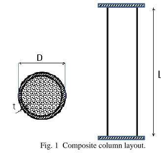
Compressive strength and modulus of elasticity for ordinary concrete are (24 MPa) and (23100 MPa) respectively, Poison's ratio for concrete and steel are (0.15) and (0.30) respectively. The yielding of steel and modulus of elasticity are (368 MPa) and (200000 MPa) respectively. Column dimensions are (160 mm) external diameter of steel section with (2.8 mm) in thickness and (1500 mm) height. No shear connectors inside the steel section and the concrete without main reinforcements.
The composite column was checked as dimensions and capacity designed based on the AISC – 360 – 2016 [19]. Mass of concrete and Hollow Steel Section (HSS) are (25 kN/m3) and (78.5 kN/m3) for concrete and steel section, respectively. The diameter to the wall thickness ratio is (57.15) is less than the limit in equation (1) which is (81.6). The steel plate at the top and bottom of the column is (160 mm) in diameter with (25 mm) in thickness. Figure (1) shows the composite column layout with ended boundary conditions at the top and bottom.
Fig. 1 Composite column layout.
C. High strength concrete
such as compressive strength, splitting tensile strength, modulus of rupture and modulus of elasticity. The properties of straight steel fibers are listed in Table (1) and shown in Figure (2). Figure (3) and (4) show the curing and testing of the specimens, respectively.
TABLEI STEEL FIBER SPECIFICATIONS
Length (mm)
Diameter (mm)
Aspect ratio
Density (kg/m3)
Ultimate tensile strength (MPa)
10 0.1 100 7800 1180
Fig. 2 Steel fiber
Fig. 3 Curing of the specimens
Fig. 4 Testing of the specimens
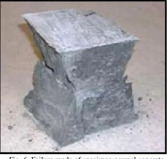
The superplasticizer type used to increase the concrete workability is sulphonate melamine, and naphthalene formaldehyde condensates with density (1.07 kg/m3) and the dosage were (1%) by weight. The reactive powder concrete (RPC) with (2%) of steel fiber, (30%) silica fume and water-cement ratio (0.19) gave cube compressive strength (158.67
MPa), and the mode of failure is shown in Figure (5) and Figure (6) respectively. Based on the test, the reactive powder concretehas a modulus of elasticity (49100 MPa), splitting tensile strength (9.50 MPa) and modulus of rupture (13.25 MPa).
Fig. 5 Failure mode of specimen RPC with steel fibers
Fig. 6 Failure mode of specimen normal concrete
D. Finite elements approach
make the model resonance range for modal analysis. The finite elements ANSYS software's was used to simulate the composite columns that subjected to static and (model and harmonic) dynamic loadings. The dynamic harmonic analysis that applied on the composite column is containing low and medium frequency range as (0-40 and 40-400 Hz). The frequency-domain analysis is based upon the dynamical response of the structure to harmonically varying load. At each frequency, the loading varies with time as sine and cosine functions. The cases adopted here are the harmonic loading that is developed due to the constant speed of the machine. The natural frequency for composite column calculated as follow:
T
f=1 (8)
In which, (T) is the period according to:
ω π 2 =
T (9)
Where, (ω) is the circular frequency calculates as follow:
m k =
ω (10)
Where, (k) and (m) is the stiffness and mass of the composite column, respectively.
III.RESULTS AND DISCUSSION
The numerical solution by finite element analysis first was checked by the maximum axial displacement with that stated in reference [9] and then analyzed the model under dynamic loading. It is showed that the static analysis results as axial displacement by finite elements approach is (8.56 mm) for normal concrete and is matching with test result by [9]. And the axial strength capacity according to the experimental test by [9], adopted in the present study was of axial load (1260 kN), and the composite column is sustained this load which is higher than the calculated strength capacity from equations mentioned above that is in case of normal concrete.
The modal analysis measures the dynamic response of the composite column during excitation. The typical excitation signals classed as impulse, and the analysis relies on Fourier series. The modal analysis uses the overall mass (equivalent mass) and stiffness of a composite column to find the various periods at which it will naturally resonate. These periods of vibration lists in Table (2) are critical in calculations and check out in the harmonic dynamic analysis. In the harmonic analysis, as it is imperative that a composite column natural frequency does not match the applied external frequency.
TABLEII MODAL ANALYSIS RESULTS
TABLEIII
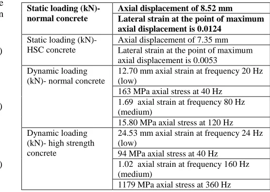
ANALYSIS RESULTS FOR STATIC AND DYNAMIC LOADINGS
Static loading (kN)- normal concrete
Axial displacement of 8.52 mm Lateral strain at the point of maximum axial displacement is 0.0124
Static loading (kN)- HSC concrete
Axial displacement of 7.35 mm Lateral strain at the point of maximum axial displacement is 0.0053
Dynamic loading (kN)- normal concrete
12.70 mm axial strain at frequency 20 Hz (low)
163 MPa axial stress at 40 Hz 1.69 axial strain at frequency 80 Hz (medium)
15.80 MPa axial stress at 120 Hz Dynamic loading
(kN)- high strength concrete
24.53 mm axial strain at frequency 24 Hz (low)
94 MPa axial stress at 40 Hz 1.02 axial strain at frequency 160 Hz (medium)
1179 MPa axial stress at 360 Hz
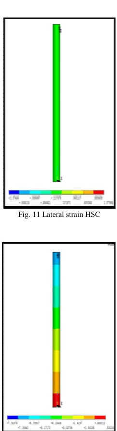
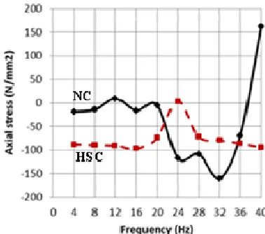
Figure (7) shows the mesh elements of the composite column and Figure (8) represents the cracks and crushing of the fillet concrete at the final stage of applied static loading in case of normal concrete. Figure (9) shows the axial displacements along the composite column, and Figure (10) shows the lateral displacement at the ultimate static loading for normal concrete. Figure (10) shows the lateral displacement-normal concrete, while Figure (11) represents the lateral strain of HSC, Figure (12) shows the axial displacement HSC. Figure (13) shows the full performance of the axial displacement of the composite column up to the full capacity load in case of normal and high strength concrete. Figure (14) shows the variation of lateral displacement under static loading at the point of maximum axial displacement in case of normal and high strength concrete. Figure (15) and (16) show the axial displacement and axial stress performance of composite column under the effect of harmonic loading in case of low frequency at the point of maximum axial displacement under the applied static loading in case of normal and high strength concrete. Figure (17) and (18) show the axial displacement and axial stress performance of composite column under the effect of harmonic loading in case of medium frequency at the point of maximum axial displacement under the applied static loading in case of normal and high strength concrete. These varied values are based on the time change and then after the applied frequency, and the values in case of HSC become less because of the stiffness of the whole section increased due to the increase in compressive strength that leads to increase in modulus of elasticity.
Case Mo de Perio d sec. Frequen cy cycle/sec Circular Frequency rad/sec Eigen value rad²/sec²
Fig. 7 Model mesh
Fig. 8 Cracks in concrete-normal concrete
Fig. 9 Axial displacement-normal concrete (mm)
Fig. 10 Lateral displacement-normal concrete (mm)
Fig. 11 Lateral strain HSC
Fig. 13 Axial displacement under static loading for normal concrete (NC) and high strength concrete (HSC).
Fig. 14 Lateral displacement under static loading at the point of maximum axial displacement for normal concrete (NC) and high strength concrete (HSC).
Fig. 15 Axial displacement under harmonic loading at the point of maximum axial displacement under static loading (low frequency) for normal concrete (NC) and high strength concrete (HSC).
Fig. 16 Axial stress under harmonic loading at the point of maximum axial displacement under static loading (low frequency) for normal concrete (NC) and high strength concrete (HSC).
Fig. 17 Axial displacement under harmonic loading at the point of maximum axial displacement under static loading (medium frequency) for normal concrete (NC) and high strength concrete (HSC).
IV.CONCLUSIONS
The composite column was checked and analyzed based on the ANSI/AISC 360-16 code under static loading and then evaluated under the effects of dynamic harmonic loading in case of normal and high strength concrete surrounding by steel tube to form the composite column. The maximum values of axial displacement by the application of the principle of stress analysis for the composite column which applies the equivalent modulus of elasticity is (8.52 mm) for normal concrete and (7.25 mm) for high strength concrete that closed with the results obtained from adopted finite elements analysis. The maximum value of axial displacement in case of normal concrete is more significant than that for high strength because of the increase in compressive strength that reflects on the modulus of elasticity value — the decrease of displacement in case of high strength around (15%).
The maximum strain in the concrete at the point of maximum displacement show enhancement in the tensile strength of concrete in the presence of steel casing column, In case of high strength concrete, the strain become less because of at the same applied loading the stress become more so that the strain decreased around (57%) which delay the occurrence of the local buckling of steel tube. The maximum displacement at low range frequency of (20 and 80 Hz) is (12.52 and 17 mm) in case of normal concrete, but at the same frequency, the displacements become (3.72 and 0.61 mm) for high strength concrete respectively. The maximum axial stress occurs at the frequency (40 and 120 Hz) for normal concrete strength, and the axial stress for HSC is less than that developed in normal concrete. The reduction in stress around (42% and 90%) at the same frequency values for normal concrete in case of low and medium frequency.
Stress due to harmonic loading of low range frequency is more than that from static loading because the frequency range for this type of loading hit this structural geometry that caused stress concentration at the point of maximum longitudinal displacement gradually. In the case of medium range frequency, the stress is lower than that for the static loading so that it is safe. The frequency of applied loading has not reached the failure due to fatigue in both cases as normal and HSC. The harmonic analysis must be taken into account to check out in the analysis and adopted in the design of composite column in case of presence of this type of loading because of the performance of the column is different under this type of loading. No resonance occurs throughout the low and medium frequency ranges because there is the infinite result. The natural frequency for composite column did not match an applied frequency from modal analysis list in Table (2) so that the composite column as a structural member may continue working and there is no structural damage.
REFERENCES
[1] Yansheng Du, Zhihua Chen, Yujie Yu “Behavior of rectangular concrete-filled high-strength steel tubular columns with different aspect ratio” Thin-Walled Structures 109 (2016) 304–318.
[2] Ming-Xiang Xiong, De-Xin Xiong, J.Y. Richard Liew “Axial performance of short concrete-filled steel tubes with high- and ultra-high- strength materials” Engineering Structures 136 (2017) 494–510. [3] Shiming Chena, Rui Zhanga, Liang-Jiu Jiaa, Jun-Yan Wangb, Ping
Gua “Structural behavior of UHPC filled steel tube columns under axial loading” Thin-Walled Structures 130 (2018) 550–563 [4] S. Gulera, F. Korkuta, N. Yaltaya and D. Yavuza “Axial behavior of
concrete filled steel tube stub columns: a review” 12th International Conference on Advances in Steel-Concrete Composite Structures (ASCCS2018) Doi:http://dx.doi.org/10.4995/ASCCS2018.2018.7602. [5] Guochang Lia, Bowen Chena, Zhijian Yanga, Yihe Fengb
“Experimental and numerical behavior of eccentrically loaded high strength concrete filled high strength square steel tube stub columns” Thin-Walled Structures 127 (2018) 483–499
[6] Zbigniew Kołakowski, "Static and dynamic interactive buckling of composite columns", Journal of theoretical and applied mechanics, 47, 1, pp. 177-192, Warsaw 2009, pp. 178 – 192.
[7] Z. Kołakowski and A. TETE, "Damping behavior of thin-walled composite columns under impact in-plane loading," Stability of Structures XIII-the Symposium, Zakopane 2012, pp. 337 – 346. [8] Nadby strzycka et al., "Buckling and post-buckling behavior of
thin-walled composite channel section column," Composite Structures, Volume 100, June 2013, pp. 195-204.
[9] Ali, A. A. et al. "Experimental behavior of circular steel tubular columns filled with self-compacting concrete under concentric load," Eng. &Tech. Journal, Vol.31, Part (A), No.14, 2013, pp.2760 – 2772 . [10] Xiaodong Ji et al., "Seismic behavior and strength capacity of steel tube-reinforced concrete composite columns," Volume 43, Issue 4, 10 April 2014 pp. 487–505.
[11] Jerome F. Hajjar, "Concrete-filled steel tube columns under earthquake loads" Progress in Structural Engineering and Materials 2(1):72-81, January 2000
[12] Hoang AL, Fehling E, Ismail M. “Numerical modeling of circular concrete-filled steel tube stub columns under concentric loading” Proceedings of the 4th International Symposium on Ultra-High Performance Concrete and High-Performance Construction Materials; 2016.
[13] Javed M. F. et al., “FE modeling of the flexural behavior of square and rectangular steel tubes filled with normal and high strength concrete” Thin-Walled Structures 119 (2017) 470–481
[14] Sabih S. “Harmonicdynamicloading response of reinforced concrete column”MATEC Web of Conferences 162, 04024 (2018) BCEE3-2017
[15] Ouyang et al. “Finite element analysis of concrete-filled steel tube (CFST) columns with circular sections under eccentric load” Engineering Structures Volume 148, 1 October 2017, Pages 387-398 [16] Sevim B “Dynamic and static behavior of a steel covered column”
Journal of Structural Engineering & Applied Mechanics 2018 Volume 1 Issue 1 Page 22-27
[17] Guochang Lia, Bowen Chena, Zhijian Yanga, Yihe Feng “Experimental and numerical behavior of eccentrically loaded high strength concrete filled high strength square steel tube stub columns” Thin-Walled Structures 127 (2018) 483–499
[18] M. M. Abbass et al., "Performance of composite concrete - encased columns of full interaction," Al-Mansour University College, Proceeding of 15th Scientific Conference 23-24 April 2016, pp. 97-113.
[19] American Institute OF Steel Construction, "Specification for structural steel buildings," an American National Standard, ANSI/AISC 360-16 July 7, 2016, pp. 1 – 620.