Using Topology Optimization to Reduce Stress
Concen-tration Factor in a Plate with a Hole
J. Jafari Fesharaki
∗S. Karimi,
Department of Mechanical Engineering, Najafabad Branch, Islamic Azad University, Najafabad, Iran.
Article info
Article history:Received10January 2019 Received in revised form 16March 2019
Accepted17March 2019
Keywords:
Stress concentration factor Topology optimization SIMP method
Abstract
This paper focuses on reducing stress concentration in a plate with a hole. For this purpose, a novel Reliever Topological Material Elimination (RTME) approach was introduced which uses the topology optimization technique to specify the best areas to remove material in order to refine flow of stress and reduce the Stress Concentration Factor (SCF), consequently. Using the Solid Isotropic Material with Penalization (SIMP) method, topology optimization was formulated. Three major elimination areas were determined from material elimination patterns observed in topology optimization. Two possible RTME cases were proposed numerically. To evaluate the efficiency of the method, finite element analyses were conducted for one previous technique and the results werediscussed. In addition, the results of finite element analysis were validated by some experimental tests. According to the final results, RTME approach gives up to 35.5% stress reduction, 44% SCF mitigation, and decrease about 28% of the initial volume. In comparison with the previous technique, using RTME is more effective in decreasing the SCF and weight of the plate, simultaneously.
Nomenclature
SCF Stress concentration factor SCP Stress concentration point
FEA Finite element analysis FEM Finite element method
TO Topology optimization FGM Functionally graded materials
PSO Particle swarm optimization PEA Principal elimination area
SEA Subsidiary elimination area VC Volume constraint
SIMP Solid isotropic material with penaliza-tion
RTME Reliever topological material elimination
1. Introduction
Though it is so desirable to have an entirely homoge-nized stress field, in practice, most of the designscon-tain design constraints which make disorders in the fields of stress. This disorder changes the flow of stress in a way that some points with more stress values than the others are created. These points are called Stress
Concentration Points (SCP’s). Typically, stress con-centration takes place by changing the cross-sectional area or where material properties change in the struc-tures with compound materials. Since stress concen-tration has a serious role in fatigue and other types of failure, it has been a major issue for designers to mit-igate the value of stress at SCP. Methods have been studied to reduce stress concentration may be divided ∗Corresponding author: J. Jafari Fesharaki (Assistant Professor)
E-mail address: [email protected]
http://dx.doi.org/10.22084/jrstan.2019.18177.1081 ISSN: 2588-2597
into four main categories [1].
The first category contains the so-called reinforc-ing methods which try to decrease the amount of stress by adding materials at SCP. Giare and Shaba-hang [2] tried to reduce the SCF around a hole in a finite isotropic plate using thecomposite reinforcing rings. Furthermore, using thefunctionally graded rings, Sburlati, Atashipour et al. [3], studied SCF in a ho-mogenous plate with a circular hole under uniaxial, biaxial, and shear in-plane loading situations. They represented an explicit formula for reducing SCF with reinforcement FGM layer. In another study, Yang and Gao [4], investigated the effect of FGM reinforc-ing layer to reduce SCF around an elliptical hole in a finite plate using the combination of the complex variable method and the conformal mapping technique. Although reinforcing techniques have high SCF reduc-tion, they make assembling difficulties and are not ap-propriate in cases with weight limitations.
The second category is about methods usingshape optimization. Briefly, shape optimization tries to mini-mize SCF via making slight geometrical changes, and it is more efficient in cases with simple geometries. Fran-cavilla et al. [5], formulated shape optimization for a piston rod as an unconstrained minimization prob-lem by merging side constraints on design variables us-ing penalty functions. Furthermore, their procedure was generally applicable. Wu [6], using parameterized geometry models, investigated the problem of finding the optimum shape with minimized SCF, for a hole in a two-dimensional plate. They presented compact parametric functions for optimized holes. Despite the efficiency observed in the aforementioned studies, the shape optimization method is not suitable where there is fixed geometry such as in a rivet hole or bolt hole. Moreover, it is mathematically complicated to obtain an exact optimal solution over this method.
Methods of the third category, use piezoelectric ac-tuators to make a smart SCF reduction. Using piezo-electric actuators in order to reduce stress concentra-tion in a plate was studied for the first time by Shah et al. [7, 8]. It was figured out that if piezoelectric with positive-strain-behavior places in compaction areas, it can make changes in stress distribution in the plate, and decreases stress concentration around the hole, consequently. Deriving a finite element formulation, they analyzed different shapes of piezoelectric patches on a square aluminum plate and figured out that there is logical relationships between the shape of patches and stress field in both plate and patches. Jafari Fe-sharaki and Golabi [9], used piezoelectric patches and presented a procedure to reduce SCF around a hole in a plate under tension. For this reason, a code was devel-oped by them, based on the particle swarm algorithm (PSO), to find the best locations of actuators. Their efforts demonstrated optimum placements of piezoelec-tric patches on the plate. Obviously, these methods are
laborious and expensive and do not guarantee a per-manent SCF reduction, i.e. they are effective in the presence of the electricity.
The fourth category includesso-called material-elimination-based methods. These techniques reduce SCF by removing material from the structure. In an earlier study, Erickson and Riley [10], investigated SCF caused by a circular hole in a finite plate under uniax-ial tension and reduced SCF by making auxiliary holes in both left/right sides of the main hole. Moreover, the size and location of auxiliary holes were optimized. Using defense hole technique, Meguid [11] studied the problem of reducing SCF in a plate with two coaxial holes under uniaxial loading. Due to creating auxil-iary holes and removing material from an area between the main holes, results showed up to reduction of SCF in the plate. Othman, Jadee et al. investigated de-fense hole system for a single-bolt double-lap compos-ite bolted joint [12]. Nagpal et al. [13], worked on a plate analogous to Erickson and Riley, and represented mitigation curves which specified locations for four re-lief holes, i.e. they achieved to a higher percentage of SCF reduction from the main hole with greater mate-rial removal, merely by creating two extra holes.
Due to decreasing the weight, requiringan easy-manufacturing process, and preserving the geomet-rical restrictions of the design, material-elimination-based methods are the most suitable methods to re-duce the SCF permanently. In the following sections, a new material-elimination-based approach called Re-liever Topological Material Elimination (RTME) is pre-sented to reduce SCF using topology optimization tech-nique.
2. Problem Description
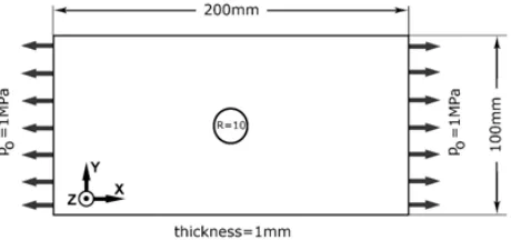
This paper investigates the stress concentration caused by a circular hole in a plate. So, a thin finite rectangu-lar aluminum plate with Young modulus of 70GPa, was considered which had a central hole. Plate was under static uniaxial tension along its length. Dimensions of the plate and the hole were considered, arbitrarily, as it is shown in Fig. 1.
2.1. Stress Concentration
The Stress Concentration Factor (SCF) is defined as the ratio of maximum stress to reference stress at a domain. Based on this definition, there are two stress concentration factors used in the literature: Ktn for when the net stress of cross-sectional area(σnet)is
as-sumed as reference stress, andKtg for when the stress of gross cross-sectional area (σ0) is assumed as
refer-ence stress. Eqs. (1) and (2) show Ktn, andKtg [14]. In this study, the widely-used definitionKtn was con-sidered.
Ktn= σmax
σnet
(1)
Ktg = σmax
σ0
(2)
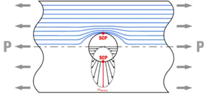
Fig. 2 shows the flow of stress and stress distribu-tion at the edge of a hole, qualitatively.
Fig. 2. The pattern of flowing stress in plate and stress distribution around the hole [14].
It is obviously understanding which maximum ten-sile stress occurs in the top/bottom of the hole. Based on Roark’s Eq. [15], which is obtained by experimental photoelastic analysis, the value ofKtn for the central hole in a plate under tension is as follows:
Ktscp= 3.00−3.13
( d w ) + 3.66 ( d w )2 −1.53 ( d w )3 (3)
where d is the diameter of the hole, and w is the width of the plate. So, the factor Ktn for the plate in Fig. 1 is equal to 2.5. regarding that dimension of the plate and the hole is constant, the value of Ktn changes only by reducing the ratio ofσmaxtoσnet. In
former material-elimination-based methods, which re-move material from plate to reduce SCF [10, 13], the flow of stress changes by creating extra circular holes near the main hole. This change in the flow of stress decreases the value of stress at SCP’s (σmax), which
decreases SCF (Ktscp), consequently. But a circular
hole may not be the best geometry for changing the stress field in the plate in order to reach to the “max-imum” SCF reduction. Hence, without assuming any specific geometry, in next section, a topology optimiza-tion problem is formulated to find the best geometry and location for eliminating material from the plate to mitigateinitial SCF and volume, simultaneously.
2.2. Topology Optimization
Topology Optimization (TO) is a kind of structural optimization that specifies the optimum material dis-tribution in a constant design area with predefined load and boundary condition [16]. TO methods owe their progress strongly to the development of com-puters and the Finite Element Method (FEM). The gradient-based TO methods were investigated at first based on the homogenization method [17, 18]. In a classic point of view, topology optimization of a con-tinuum structure isformulated as a problem of maxi-mizing the stiffness of the structure. For the domain Ω0 ∈ R3 discretized into N finite elements, it can be
expressed as:
M in/M ax: f(ρ)
Sub.to:
N
∑
i=1
ρivi≤V∗ (i= 1,2,3, . . . , N),
0≤ρ(x)≤1 (4)
Wheref(ρ)is the objective function with design vari-ableρ;vi is the volume of theithelement, andV∗is a
prescribed volume constraint [18].
As the stiffness of a structure has an inverse rela-tionship with the total strain energy of the structure, minimizing the total strain energy can be a good choice for the objective function of the TO. Based on the def-inition, the works done by surface and body forces on an elastic solid are stored inside the body in the form of strain energy, a form of potential energy. Mathe-matically, the total strain energy stored in an elastic solid occupying a regionV in the domainΩ0∈R3is:
SE =
1 2
∫∫∫
V
σijεijdxdydz. (5)
Here, SE is the strain energy,σij is the stress
ten-sor, and is the strain tensor [19]. For a homougenous isotropic linear elastic material, Eq. (5) can be ex-pressed only in terms of stress:
SE(σ) =
1 +v
2E σijσij− v
2Eσjjσkk (6)
where E is the Young’s modulus, and is the poisson ratio. Due to this direct relationship, it is expected that if minimizing the strain energy is cosidered as the objective function, TO results in increasing the stiff-ness, as well as decreasing the stress of the structure, implicitly.
In order to carry out a numerical calculation, the domain is discretized into elements. Hence, the numer-ical FE formulation of Eq. (5) is followed as:
SE=1 2
N
∑
i=1
whereuiandkiare theithelement displacement vector
and stiffeness matrix, respectively [20]. On the other hand, a continuum material property distribution is required to recover the discrete nature of the design.
Introducing the Solid Isotropic Material With Pe-nalization (SIMP) approach was a landmark in the his-tory of TO; since it presented a simple power-law re-lation to interpolate material property in a continuum design space by means of penalizing the intermediate densities [21]. This approach was then implemented by other researchers and numerical instabilities like mesh-dependency and checkerboards problems were solved, remarkably [18, 22-24]. Using the SIMP approach, the elastic tensorEijkl can be defined as:
Eijkl(x) =ρ(x)pEijkl0 , (8)
∫
Ω
ρ(x) dΩ≤V∗, p >1, 0≤ρ(x)≤1, x∈Ω0
here,ρ(x)is the material density at coordinatex[18]. Therefore, due to the SIMP description of the material property in the domain, the strain energy of the ith
elementSEiis expressed as:
SEi =f(xi)uTik
0
iui=f(xi)E0εTiD0εi (9)
where f(xi) is the material density function, E0 and
k0
i are a constant Young’s modulus and element
stiff-ness matrix related to the base material, respectively, and D0 is a stress-strain relation matrix in terms ofv
[20, 25].
Finally, the TO problem is formulated to minimize the total strain energy of the plate [18, 20]:
min
ρ :SE(X) =
1 2U
TKU
Sub.to:
N
∑
i=1
ρivi≤V∗ (i= 1,2,3, . . . , N) (10)
X ={ρ1, ρ2, ρ3, . . . , ρN}, 0≤ρi≤1
KU =F
where X is the design variable vector, andU, K, and F are global displacement vector, stiffness matrix, and force vector, respectively. ρi is the density of each
ele-ment. It can vary in the range of 0-1, and showing the presence ifρi= 1, or absence ifρi= 0, in an elementof
the material.
To find the most proper volume constraint (v∗) for the TO problem, as a classic scheme, TO was con-ducted for several times with different allowable vol-ume constraints, and then the lightest optimal struc-ture satisfying the objective function was selected. Fur-thermore, this fashion helps all patterns of removing material for different volume constraint to be revealed, which is useful in RTME approach to classifyelimina-tion areas due to their importance in reducing the SCF.
3. Numerical Implementation and
Re-sults
In this paper, all of the numerical analyses were-done using Abaqus commercial software. Twenty-node quadratic C3D20R elements were used for meshing the plate, and the best element size was determined to be 0.001 due to a mesh convergence study. Hence, the FEA stress value at SCP was 3.164MPa and, therefore, the SCF was 2.53. It can be seen that it is acceptably close to the experimental SCF2.51 calculated from Eq. (3). Experience shows that to have the most accurate results out of a SIMP-TO, a penalty factor p ≥ 3 is required [18]. In this paper, the penalty factor p= 3 was considered for all TO. In addition, the convergence criterion for the density of each element during an it-eration was considered to be 0.002 in this study.
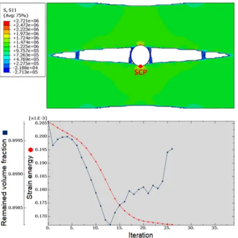
At the first attempt, volume constraint was as-sumed to be 90% of the initial volume. The result of the TO is shown in Fig. 3. It can be seen that the total strain energy was minimized after TO. Moreover, the amount of maximum stress decreased from 3.164MPa, which was in the main plate, to 2.721MPa after TO. So, it indicates that the procedure eliminates the ma-terial efficiently in order to reduce stress at SCP. But it may not be the maximum stress reduction, because the volume constraint has a substantial role in remov-ing material, and it impacts upon TO output, directly.
Fig. 3. Results of topology optimization with volume constraint 90%.
In point of fact, all previous material-elimination-based methods eliminate material by creating circular holes at these areas, too. Hence, this area is called Principal Elimination Areas (PEA’s) since it has the main role in modifying the flow of stress in order to reduce the value of stress at SCP. Another elimination occurs in the up/down sides of the hole being more obvious when TO isallowed to eliminate more material. These areas are called subsidiary elimination areas (SEA’s). Addi-tionally, some sporadic elimination appears when vol-ume constraints become less than 80%. Clearly, these sporadic eliminations are completely adverse since they cause local stress concentrations around themselves and even change the location of SCP. Fig. 5 shows these three areas observed in TO.
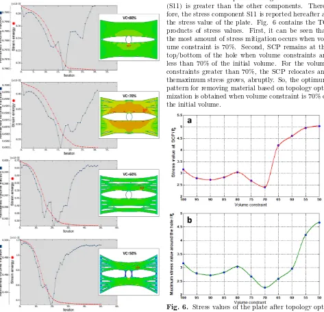
Fig. 4. Topology optimization results with volume constraints 80%, 70%, 60% and 50%.
Fig. 5. Material elimination areas in the plate.
Since the plate is thin and loading is uniaxial, a plane-stress condition can be considered for the plate where the stress component along tension direction (S11) is greater than the other components. There-fore, the stress component S11 is reported hereafter as the stress value of the plate. Fig. 6 contains the TO products of stress values. First, it can be seen that the most amount of stress mitigation occurs when vol-ume constraint is 70%. Second, SCP remains at the top/bottom of the hole when volume constraints are less than 70% of the initial volume. For the volume constraints greater than 70%, the SCP relocates and themaximum stress grows, abruptly. So, the optimum pattern for removing material based on topology opti-mization is obtained when volume constraint is 70% of the initial volume.
4. Evaluation of the RTME Approach
In this section, two possible RTME cases are consid-ered: case #1: the plate with PEA and SEA elimina-tion; case #2: the plate with only PEA elimination. Fig. 7 shows the results of FEA for the plate after applying a former material-elimination-based method [26], and both above-mentioned RTME cases.It can be seen that in all three cases SCP remains in its initial location. If the SCP’s relocate due to material eliminations to a new spot near the elimi-nation areas, the number of SCP’s will become more than 2, due to symmetry. Preventing this problem is more noticeable in cases when a designer decides to use multiple techniques to reduce SCF, e.g. using material-elimination-based methods besides using re-inforcing techniques, this relocations and increases in the number of SCP’s, certainly cause difficulties.
Fig. 7. FEA for applying the previous technique [26] and RTME approach.
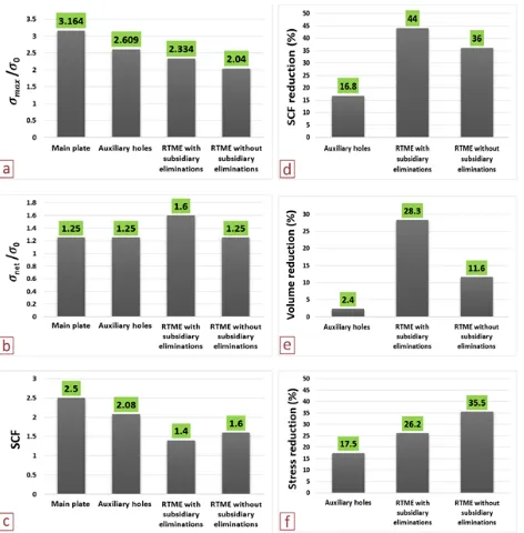
The FEA results of applying these three methods to the plate are provided in Fig. 8. σmax is S11 stress
value at the SCP, andσ0=P0. As Fig. 8a shows, the
value of maximum stress at SCP decreases the most
when RTME is considered for the plate. Fig. 8b, shows the value of stresses in the cross-sectional area where the SCP is located. By removing the SEA, the value of stress in the cross-sectional area at SCP’s increases. Based on Eqs. (1), these changes in values of stress presented in Figs. 8a and 8b change the value of the initial SCF (Kt) shown in Fig. 8c for each case. It
should be noticed that in both RTME cases the initial SCF decreases.
Fig. 8d shows that SCF reduction is about 2.6 times greater than when RTME is applied to the plate. But as Fig. 8f shows, the maximum percentage of stress reduction in the plate is achieved when only PEA is removed due to RTME approach. It conveys that re-moving only the PEA gives a suitable design in cases where having a design with the minimum stress value at SCP is the only concern for the designer. However, Fig. 8e denotes that for when the decrease in weight of the design is as important as decreasing the maximum stress value, removing SEA and PEA together can be a more desired choice.
Fig. 8. Final results for applying the previous tech-nique [26] and RTME approach to the initial plate.
Table 1
Data from experimental tests and finite element analyses.
Specimens Strain measured
by experiment ×10−6
Strain measured
by FEA×10−6 Error (%)
Specimen #1 657 626 4.7
Specimen #2 372 322 13.4
Specimen #3 472 412 12.7
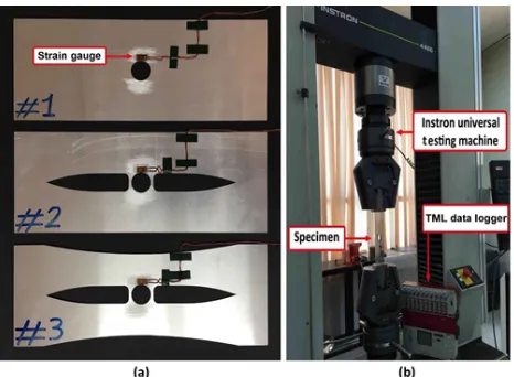
Dimensions of the plates were considered as what it is in Fig. 1. Furthermore, specimens were considered 6cmgreater in length to insert properly in wedge grips of the tensile testing machine. In addition, the strain gauges BF350-6AA(11) with grid size6.1×3.1mmwere used in this study.
Fig. 9. Experimental test; a) Specimens prepared for the tests: (#1) The initial plate; (#2) The initial plate without PEA; (#3) The initial plate without PEA and SEA; b) Testing equipment.
The speed of pulling jaws was 2mm/min in all tests. Using a data logger, data for strains were obtained dur-ing the tensile test from strain gauges installed at the top of the holes (at SCP’s). Fig. 9 shows the specimens and the equipment used for the experiment. Table 1, shows the data of the experiments versus the results of finite element analyses in the sameconditions. As can be seen, experimental results are acceptably close to numerical results. However, it can be seen that the er-ror between experimentally measured strains and FEA strains are more in case #2 and case #3. The com-plexity of the shape of the RTME plates for meshing in FEA can be one reason for this difference. In addi-tion, using more strain gauges may decrease the error.
6. Conclusions
Reducing stress concentration factor (SCF) in an axi-ally loaded thin plate with a central hole was the main purpose of this study. A novel material-elimination-based approach was implemented in this paper called Reliever Topological Material Elimination (RTME).
The topology optimization technique was used to spec-ify the locations for eliminating material from the plate in order to reduce SCF. These eliminations refined the flow of stress and prevented local stress from con-centrating which reduces SCF, consequently. Hence, topology optimization was formulated based on the widely used SIMP method and was applied to the plate. Then optimum volume constraint for topology opti-mization wasdetermined. Results indicated the PEA’s, which are the most appropriate areas to remove mate-rialin order to decrease the maximum stress and SCF. Moreover, the subsidiary areas called SEA were ob-served, which can be eliminated together with PEA if having less weight is as important as having less SCF for the designer.
Afterward, three plates were modeled based on RTME and one other previous material-elimination-based technique, and finite element analyses were con-ducted for them. Results were compared and dis-cussed in detail. Finally, numerical results were val-idated using some experimental tests. As an inference, although, removing circular holes in previous meth-ods are more effortless rather than removing RTME areas, but RTME approach reduces the initial SCF about 2.6 times more than previous methods. Fur-thermore, RTME approach eliminates material from plate up to 11.8 times more than former methods. Hence, RTME approach can be used as an effective material-elimination-based approach for reducing SCF, especially in cases with weight or cost restrictions.
References
[1] S. Nagpal, N. Jain, S. Sanyal, Stress concentra-tion and its mitigaconcentra-tion techniques in flat plate with singularities-a critical review, Eng. J., 16(1) (2012) 1-15.
[2] G.S. Giare, R. Shabahang, The reduction of stress concentration around the hole in an isotropic plate using composite materials, Eng. Fract. Mech., 32(5) (1989) 757-766.
[4] Q. Yang, C.F. Gao, Reduction of the stress con-centration around an elliptic hole by using a func-tionally graded layer, Acta Mech., 227(9) (2016) 2427-2437.
[5] A. Francavilla, C.V. Ramakrishnan, O. Zienkiewicz, Optimization of shape to mini-mize stress concentration, J. Strain Anal., 10(2) (1975) 63-70.
[6] Z. Wu, Optimal hole shape for minimum stress concentration using parameterized geometry mod-els, Struct. Multidiscip. Optim., 37(6) (2009) 625-634.
[7] D.R. Shah, S.P. Joshi, W. Chan, Stress concentra-tion reducconcentra-tion in a plate with a hole using piezo-ceramic layers, Smart Mater. Struct., 3(3) (1994) 302-308.
[8] D.R. Shah, S.P. Joshi, W. Chan, Static structural response of plates with piezoceramic layers, Smart Mater. Struct., 2(3) (1993) 172-180.
[9] J. Jafari Fesharaki, S.i. Golabi, Optimum pattern of piezoelectric actuator placement for stress con-centration reduction in a plate with a hole using particle swarm optimization algorithm, Proceed-ings of the Institution of Mechanical Engineers, Part C: J. Mech. Eng. Sci., 229(4) (2015) 614-628.
[10] P.E. Erickson, W.F. Riley, Minimizing stress con-centrations around circular holes in uniaxially loaded plates, Exp. Mech., 18(3) (1978) 97-100.
[11] S.A. Meguid, Finite element analysis of defence hole systems for the reduction of stress concentra-tion in a uniaxially-loaded plate with two coaxial holes, Eng. Fract. Mech., 25(4) (1986) 403-413.
[12] A.R. Othman, K.J. Jadee, M.Z. Ismadi, Mitigat-ing stress concentration through defense hole sys-tem for improvement in bearing strength of com-posite bolted joint, Part 1: Numerical analysis, J. Compos. Mater., 51(26) (2017) 3685-3699.
[13] S. Nagpal, S. Sanyal, N. Jain, Mitigation curves for determination of relief holes to mitigate stress concentration factor in thin plates loaded axially for different discontinuities, Int. J. Eng. Innova-tive Technol., 2(3) (2012) 1-7.
[14] W.D. Pilkey, D.F. Pilkey, Peterson’s Stress Con-centration Factors, John Wiley & Sons Publisher, Inc. (2007).
[15] W.C. Young, R.G. Budynas, Roark’s Formulas for Stress and Strain, Seventh Edition McGraw-Hill Publisher, (2002).
[16] G.I.N. Rozvany, T. Lewiński, Topology Optimiza-tion in Structural and Continuum Mechanics, Springer Publisher, (2014).
[17] M.P. Bendsoe, N. Kikuchi, Generating optimal topologies in structural design using a homoge-nization method, Compu. Methods Appl. Mech. Eng., 71(2) (1988) 197-224.
[18] M.P. Bendsoe, O. Sigmund, Topology Optimiza-tion: Theory, Methods, and Aplications, Springer Science and Business Media Publisher, (2013).
[19] M.H. Sadd, Elasticity: Theory, Applications, and Numerics, Academic Press,(2009).
[20] E. Lee, A Strain Based Topology Optimization Method, Rutgers University-Graduate School-New Brunswick Publisher, (2011).
[21] M.P. Bendsoe, Optimal shape design as a material distribution problem, Struct. Optim., 1(4) (1989) 193-202.
[22] M. Zhou, G.I.N. Rozvany, The COC algorithm, Part II: Topological, geometrical and general-ized shape optimization, Comput. Methods Appl. Mech. Eng., 89(1-3) (1991) 309-336.
[23] O. Sigmund, On the design of compliant mech-anisms using topology optimization, J. Mech. Struct. Mech., 25(4) (1997) 493-524.
[24] A. Rietz, Sufficiency of a finite exponent in SIMP (power law) methods, Struct. Multidiscip. Optim., 21(2) (2001) 159-163.
[25] E. Lee, H.C. Gea, A strain based topology opti-mization method for compliant mechanism design, Struct. Multidiscip. Optim., 49(2) (2014) 199-207.
[26] S. Sanyal, P. Yadav, Relief holes for stress mit-igation in infinite thin plates with single circu-lar hole loaded axially, in ASME 2005 Interna-tional Mechanical Engineering Congress and Ex-position, American Society of Mechanical Engi-neers, (2005).