Available Online at www.ijpret.com 234
INTERNATIONAL JOURNAL OF PURE AND
APPLIED RESEARCH IN ENGINEERING AND
TECHNOLOGY
A PATH FOR HORIZING YOUR INNOVATIVE WORK
IMAGE COMPRESSION USING VLSI APPLICATION OF DISCRETE WAVELET
TRANSFORM (DWT)
AMIT S. PATIL1, DEVENDRA P. JUMADE2 1. PG Student, G. H. Raisoni College of Engineering and Technology, Amravati, Maharashtra, India
2. PG Student, Dr. Sau Kamaltai Gawai Institute of Engineering and Technology, Darapur, Maharashtra, India
Accepted Date: 05/03/2015; Published Date: 01/05/2015
\
Abstract: This research suggests a new image compression scheme with pruning proposal based on discrete wavelet transformation (DWT). The effectiveness of the algorithm has been justified over some real images, and the performance of the algorithm has been compared with other common compression standards. The design follows the JPEG2000 standard and can be used for both lossy and lossless compression. In order to reduce complexities of the design, linear algebra view of DWT and IDWT has been used in this paper. This design can be used for image compression in a robotic system
Keywords: Discrete wavelet transforms (DWT), image compression, Thresholding, VLSI design, JPEG 2000
Corresponding Author: MR. AMIT S. PATIL
Access Online On:
www.ijpret.com
How to Cite This Article:
Available Online at www.ijpret.com 235
INTRODUCTION
With the use of more and more digital still and moving images, huge amount of disk space is required for storage and manipulation purpose. For example, a standard 35-mm photograph digitized at 12µm per pixel requires about 18Mbytes of storage and one second of NTSC-quality color video requires 23 Mbytes of storage [1]. That is why image compression is very important in order to reduce storage need. Digital images can be compressed by eliminating redundant information present in the image, such as spatial redundancy, spectral redundancy and temporal redundancy. The removal of spatial and spectral redundancy is often accomplished by transform coding, which uses some reversible linear transform to decorrelate the image data [2]. JPEG is the most commonly used image compression standard in today’s world. Joint Photographic Experts Group (JPEG) is an ISO standard committee with a mission on “Coding and compression of still images”. It’s jointly supported by ISO and ITU-T. But researchers have found that JPEG has many limitations. In order to overcome all those limitations and to add on new improved features, ISO and ITU-T has come up with new image compression standard, which is JPEG2000. The JPEG2000 is intended to provide a new image coding/decoding system using state of the art compression techniques, based on the use of wavelet technology. Its wide range of usage includes from portable digital cameras through pre-press, medical imaging. Right now, JPEG2000 is composed of 6 main parts [3]. The two important parts in the coding/decoding processes of JPEG2000 are Wavelet Transform and Arithmetic Coding. Since the later is widely implemented, this paper focuses on the hardware Application of discrete wavelet transform (both FDWT and IDWT), which will provide the transform coefficients for later stage and is one key part of JPEG2000 Application.
2. OVERVIEW OF DWT ALGORITHM
Available Online at www.ijpret.com 236 giving a detailed image. Hence, the averages/smooth variations are demanding more importance than the details [4].
In wavelet analysis, A signal can be separated into approximations or averages and detail or coefficients. Averages are the high-scale, low frequency components of the signal. The details are the low-scale, high frequency components. If we perform forward transform on a real digital signal, we wind up with twice as much data as we started with. That’s why after filtering down sampling has to be done. The inverse process is how those components can be assembled back into the original signal without loss of information. This process is called reconstruction or synthesis. The mathematical manipulation that effects synthesis is called the inverse discrete wavelet transform. The DWT algorithm consists of Forward DWT (FDWT) and Inverse DWT (IDWT) which are shown in fig. 1 and 2 respectively. The FDWT can be performed on a signal using different types of filters such as db7, db4 or Haar. The Forward transform can be done in two ways, such as matrix multiply method and linear equations. In the FDWT, each step calculates a set of wavelet averages (approximation or smooth values) and a set of details. If a data set s0, s1, ... sN-1 contains N elements, there will be N/2 averages and N/2 detail values. The averages are stored in the upper half and the details are stored in the lower half of the N element array.
Available Online at www.ijpret.com 237
Figure -2: Block diagram of IDWT
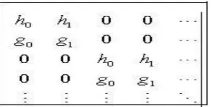
In the matrix multiply method [6] of the forward transform, the first average is calculated by the inner product of the signal [s0, s 1, ... sN-1] and the scaling vector, of the same size, [h0, h1, 0, 0,...,0]. The first detail is calculated by the inner product of the signal and the wavelet vector [g0, g1, 0, 0, …., 0]. The next average and detail values are calculated by shifting the scaling and wavelet vectors by two and then calculating the inner products. In the case of the wavelet transform using Haar filter, the Scaling function coefficients 0.5, h1 = 0.5 are h0 = and Wavelet function g0 =0.5, g1 = -coefficients are 0.5. The scaling and wavelet values for the forward transform are shown in the fig. 3 in matrix form.
Available Online at www.ijpret.com 238 On the other hand, the following linear equations no (1) and (2) can be used to calculate an average (ai) and a detail (di or ci) from an odd and even element in the input data set :
ai = (si + si+1)/2 (1)
di = (si - si+1)/2 (2)
In the IDWT process, to get the reconstructed image, the wavelet details and averages can be used in the matrix multiply method and linear equations. For the matrix multiply method, the Scaling function coefficients are h0 = 1, h1 = 1 and Wavelet function coefficients are g0 = 1, g1 = -1.
The IDWT process can be performed using the following linear equations (3) and (4).
si = ai + di (3)
si+1 = ai – di (4)
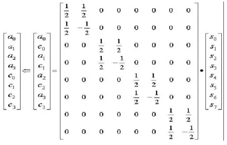
A single wavelet transform step using a matrix algorithm involves the multiplication of the signal vector by a transform matrix, which is an N X N operation (where N is the data size for each transform step). In contrast, linear equations need only N operations. The matrix form of the wavelet transform is both computationally inefficient and impractical in its memory consumption. The first step of the forward transform (FDWT) for an eight element signal is shown in figure 4. Here signal is multiplied by the forward transform matrix with haar filter coefficients. For the inverse transform (IDWT), here the signal is reconstructed by the following multiplication. It is shown in figure 5.
Available Online at www.ijpret.com 239
Figure -5: IDWT using an eight element signal.
3. APPLICATION OF DWT AND IDWT ALGORITHM
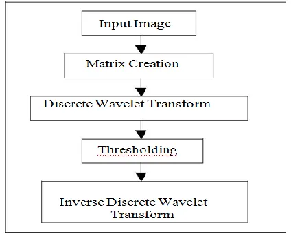
In this section we will discuss how to implement 2D FDWT and IDWT together with thresholding in MATLAB. In the FDWT part the input data will be transferred from time domain to scale domain. Then in thresholding part some of the coefficients will be set to zero and in the IDWT part the coefficients will be transferred back into time domain. The block diagram of MATLAB Application is shown in the figure 6.
Figure -6: Steps in MATLAB Application.
While implementing the algorithm in MATLAB the matrix multiplication method has been used. We have tested the ‘barbara.png’[8] as the image input file and also 8 randomly chosen image co-efficients for MATLAB simulation.
Available Online at www.ijpret.com 240 Finally, the design codes of DWT have been downloaded into FPGA board for verifying the functionality of the design.
4. SIMULATION RESULTS
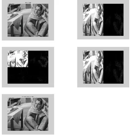
“barbara.png” was selected as the 2D image that will be used as input for the MATLAB simulation. The simulation results are given in figure 7.
Figure -7: MATLAB Simulation results on “barbara.png” image.
Table 1: Comparison of MATLAB and VHDL Simulation
Input MATLAB VHDL
Co-efficients simulation simulation
result result
1100 1100 1100
1200 1200 1200
1000 1000 1000
1200 1200 1200
1400 1400 1400
1200 1200 1200
1400 1400 1400
Available Online at www.ijpret.com 241
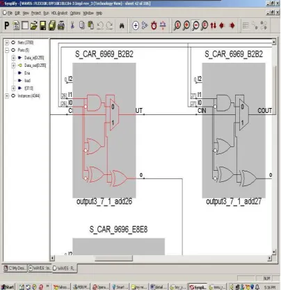
5. SYNTHESIS RESULTS
Synthesis is performed to transform the VHDL code into logic gate level using Simplify 7.0 by Simplicity. After synthesis, 3 RTL views and 106. The achieved system frequency is 10.8 MHz. In this design 64 bit registers have been used.
Figure -8: Zoomed Technology View of the Design
6. DISCUSSION
This work focuses on the digital VLSI Application of DWT (FDWT and IDWT) algorithm using VHDL. ‘db7’ filter can be used in MATLAB for better performance while ‘haar’ can be used in VHDL for simplification. We have found that higher decomposition is expected to cause higher compression ratio. In order to reduce the complexity and increase computation speed, linear algebra equations of DWT are used while implementing the algorithm in VHDL.
7. CONCLUSION
Available Online at www.ijpret.com 242
8. REFERENCES
1. L. Bottou, P. G. Howard, and Y. Bengio, “The Z-Coder Adaptive Binary Coder, Proc. IEEE DCC, pp. 13-22, Mar. 1998.
2. Rabbani M, Jones P (1991) Digital Image Compression Techniques.(SPIE tutorial texts in optical engineering, vol TT7) SPIE press, Washington.
3. JPEG official website,
4. www.jpeg.org/jpeg2000.html , visited on 18/7/03
5. Wavelets and Filter Banks by Gilbert Strang Wellesley-Cambridge Press, 1997
6. Ripples in Mathematics: the Discrete Wavelet Transform by Arne Jense, Anders la Cour-Harbo, Springer, 2001