Available Online at www.ijergs.in
Volume - 4, Issue - 6, November - December - 2018, Page No. 140 - 145
Corresponding Author:Monika Tanwani, Volume -4, Issue - 6, November – December 2018, Page No. 140 - 145
Pag
e140
Branchline Coupler as Duplexer
1
Monika Tanwani, 2Smriti jain, 3Shailesh kapur, 4Ravinder Singh Maan
1, 2,3
Department of Electronics and Communication, Arya College of Engineering and Research Center
Jaipur (Raj.), INDIA
E-mail: [email protected],[email protected], [email protected], [email protected]
Abstract
This paper presents design of branch line coupler as a duplexer for 3 GHz frequency. This paper also presents
connections of transmitter, antenna, and receiver with different port of branch line coupler to make them work as a
duplexer. Simulation is done using Serenade SV software for various parameters. Simulated values of S-parameters at 3
GHz had been reported. The values of return loss and transmission loss at 3 GHz had been reported. After analyzing the
results we had concluded that this proposed duplexer can provide good isolation between transmitter and receiver.
Keywords: Duplexer, Hybrid coupler, branch line coupler, Return loss, Transmission loss.
Introduction
In radar and radio communications systems, there should be isolation between the receivers and transmitter and this is
achieved by sharing a common antenna. This is the basic principle of duplexer. In duplexer a single antenna is used for
both transmission and reception of signal or in other words we can say that a duplexer is an electronic device in which
bi-directional (duplex) communication is allowed over a single path. In radar, a transmit-receive (TR) switch is present that
alternately connects the transmitter and receiver to a common shared antenna. The switch consists of a gas-discharge tube
that is connected between the input terminals of the receiver. When the transmitter is active, it causes the tube to start
conducting due to resulting high voltage and shorting together the receiver terminals[1].
The sender can be both sides for both the sender and the recipient with the help of the same antenna, in or at the same
frequency. This concept uses a radar, where the signal would be counter frequency very close to the frequency of
transmitted signal, such as the T / R situation. It is a network of three ports allowing the sender and receiver the radar or
communications system with the help of only one antenna. It can also be used as a roller device unit double-sided prints
in low-power applications, or it can be used in a T / R Kafraz radioactive gas radar Almigawat. It requires a sender unit
Duplex low between the sender and the antenna in transfer (less than dB 1 desirably), high isolation between the sender
and the recipient (as much as 80 dB for systems Almigawat), low loss between the antenna and the recipient under the
reception (less than 1 dB desirably) and quick transfer between the sender and recipient, and sometimes "automatically
replaced by the transmittal signal, and sometimes by the command signal [1,12].
While designing a duplexer is one should kept in mind this receiver and transmitter must be isolated from each other. In
other words, the phase change between receiver and transmitter must be 180 °.There are wide variety of duplexers are
available which can accomplished this task. Various types duplexers are circulators, diodes such as PIN diodes are
available. But at the same time microwave circuitry such as phase shifters can also be used as duplexers. Phase shifters
© IJERGS, All Rights Reserved.
Pag
e141
Pag
e141
Pag
e141
Pag
e141
Pag
e141
Pag
e141
Pag
e141
Pag
e141
Pag
e141
Pag
e141
Pag
e141
Pag
e141
Pag
e141
Pag
e141
Pag
e141
Pag
e141
Pag
e141
Pag
e141
Pag
e141
Pag
e141
Pag
e141
duplexers. The advantage of using microwave circuitry such branch line coupler as a duplexer is due to their A flat
structure that does not require any active or negative elements, so there is no way to sound through these devices.
This paper presents designing of duplexer using 90 degree hybrid or branch line coupler. While designing a duplexer
there are three most important thing we should keep in mind are firstly, at the time of transmission, transmitter should be
connected to the antenna and disconnected from the receiver. Secondly, during reception receiver should be connected to
the antenna and disconnected from the transmitter. Thirdly, there should be sufficient isolation between transmitter and
receiver at all times. This isolation between transmitter and receiver can be provided if we provide 180 degree phase shift
between transmitter and receiver and as we all know branch line coupler or 90 degree hybrid provides 90 degree phase
shift between its output. So if we use two branch line coupler sections then together they provide 180 degree phase shift.
So if transmitter and receiver are connected at its output ports then 180 degree phase shift can be achieved and this
provide good and complete isolation between transmitter and receiver. Branch-line-couplers are 3 dB direct couplers that
have a phase difference between 90 and 10 deep brain. This type of hybrid is often made in micro strip line or strip line
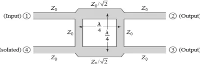
form as shown in Figure 1.1 and is also known as a branch-line hybrid.
Figure 1.1.Geometry of Branchline Coupler
Required all ports are adjusted. If the force in port 2 is divided into port 1, then the phase difference between the output
ports is 90 degrees. Without power is connected to port 4, it is an isolated port. There are restrictions on setting the output
so it can always be ported on the side of the intersection of the input and the remaining port on the same side of the input
port is the decorated port. [1]
Now we are using this branch line coupler as a duplexer so we had to arrange the connection of transmitter, receiver and
antenna accordingly. By placing the transmitter at input port 1, receiver at isolated port 4, a 50Ω termination at port 2 and
at one of the output port 3 antenna is placed. The power moves from transmitter to antenna in quadrature phases, and the
signal is send back to the receiver by the antenna. In this way, isolation is achieved between transmitter and receiver, also
they both are completely unaffected by each other. Here in this design with receiver we have to used mixer for
up-conversion and down up-conversion, power divider.
Design
Now with reference to figure 1.1 we had designed the 90 degree hybrid accordingly on the Serenade software. According
to the figure length of a and b arms is λ/2 and Z0 is the characteristic impediment of the transmission line. It can be seen
in the figure that there are two horizontal and two vertical arms designated as ‘a’ and ‘b’ arms respectively. Impedance of
‘a’ arm is Z0 / and ‘b’ arm is Z0 where Z0 is the characteristics impedance of the line and electrical length of 90 o
. The
impedance values of all other arms are 50Ω.
© IJERGS, All Rights Reserved.
Pag
e142
Pag
e142
Pag
e142
Pag
e142
Pag
e142
Pag
e142
Pag
e142
Pag
e142
Pag
e142
Pag
e142
Pag
e142
Pag
e142
Pag
e142
Pag
e142
Pag
e142
Pag
e142
Pag
e142
Pag
e142
Pag
e142
Pag
e142
Pag
e142
The value of transmission line impedance (Z0) = 50 ohm.The value of ‘a’ arm impedance (ZA) = Z0 / = 35.4 ohm. The
value of ‘b’ arm impedance (ZB) = Z0 = 50 ohm. By using Serenade SV software simulation has been done for analyzing
the results. In the proposed duplexer,branchline coupler had been designed for 3 GHz frequency for providing phase
difference of 90 degree. And accordingly if we used two branchline coupler then together they will provide total 180
degree phase shift between transmitter and receiver. Transmission lines of combination with impedances 50 ohm and
35.34 ohm provide power division and phase change at output ports.
Figure.1.2 Figure showing design of branchline coupler
All the input values such as characteristic impedance, electrical length and frequency are shown in figure 1.2 which are to
used in serenade software for making the design. The screenshot of the design of branchline coupler by using the above
input values on serenade software is shown in figure 1.3.
Figure 1.2 Screen shot for the design of Branchline Coupler using Serenade Software. Impedance Impedance Electrical
Length
ZA 35.4 90
ZB 50 90
© IJERGS, All Rights Reserved.
Pag
e143
Pag
e143
Pag
e143
Pag
e143
Pag
e143
Pag
e143
Pag
e143
Pag
e143
Pag
e143
Pag
e143
Pag
e143
Pag
e143
Pag
e143
Pag
e143
Pag
e143
Pag
e143
Pag
e143
Pag
e143
Pag
e143
Pag
e143
Pag
e143
Simulated Results
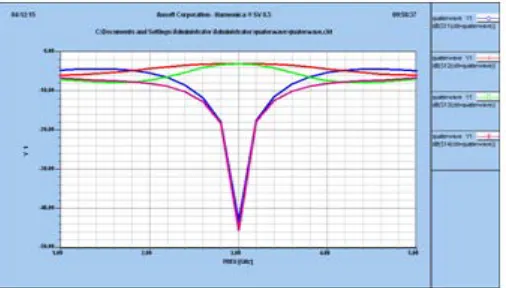
Different S parameters are measured for 3 GHz 90 degree hybrid coupler such as S11,S12,S13,S14. The values of return loss
and transmission loss had been reported at 3 GHz and frequencies nearby it. The S11 parameter represents the return loss
at port 1 i.e the amount of power that is reflected back. It is also known as reflection coefficient. The values of return loss
at different frequency should be less than -10dB. If value of S11 is -10 dB that means 3dB of power is reflected back and
rest is delivered to antenna. The delivered power is either radiated or absorbed as losses. Similarly, S12 represent the
transmission loss i.e power received at port 1 relative to power input at port 2. Also transmission loss should also be less
© IJERGS, All Rights Reserved.
Pag
e144
Pag
e144
Pag
e144
Pag
e144
Pag
e144
Pag
e144
Pag
e144
Pag
e144
Pag
e144
Pag
e144
Pag
e144
Pag
e144
Pag
e144
Pag
e144
Pag
e144
Pag
e144
Pag
e144
Pag
e144
Pag
e144
Pag
e144
Pag
e144
S-parameter versus frequency graph
Fig.1.3 Simulated S11, S12, S13 And S14 For The 3ghz Branchline Coupler
Table 1.2: Different s parameters for 3ghz branchline coupler
Table 1.3: Angular Difference For 3ghz Branchline Coupler
FREQ [GHz] Ang(S12[deg]) Ang(S13[deg])
2.4 80.91 162.63
2.6 53.55 140.94
2.8 26.21 115.96
3 -0.72 89.27
3.2 -27.74 62.57
3.4 -55.29 37.59
3.6 -82.91 16
3.8 -109.73 -1.51
4 -135.3 -15.95
4.2 -159.72 -29.24
4.4 176.69 -42.98
4.6 153.54 -57.9
4.8 130.55 -74.12
5 107.49 -91.52
Conclusion
Hence we concluded that simulated results shows good values of return and transmission losses at and nearby 3 GHz
© IJERGS, All Rights Reserved.
Pag
e145
Pag
e145
Pag
e145
Pag
e145
Pag
e145
Pag
e145
Pag
e145
Pag
e145
Pag
e145
Pag
e145
Pag
e145
Pag
e145
Pag
e145
Pag
e145
Pag
e145
Pag
e145
Pag
e145
Pag
e145
Pag
e145
Pag
e145
Pag
e145
provides good isolation between transmitter and receiver but since we want 180 degree phase shift between transmitter
and receiver so we have to use two branchline couplers to obtain complete isolation i.e 180 degree phase shift between
both.
References
1. Pozar, D. M., Microwave Engineering, 3rd edition, John Wiley & Sons, Inc 2004.
2. Balanis, C.A., Antenna Theory, 3rd edition, John Wiley & Sons, Inc 2004.
3. Chen, X. Q., X. W. Shi, Y. C. Guo, and C. M. Xiao, “A novel dual band transmitter using microstrip defected
ground structure,”Progress In Electromagnetics Research, PIER 83, 1–11, 2008.
4. Oskouei, D., H. K. Forooraghi, and M. Hakak, “Guided and leaky wave characteristics of periodic defected ground
structures,”ProgressIn Electromagnetics Research, PIER 73, 15–27, 2007.
5. Fooks, E. H. and R. A. Zakarevicius, Microwave Engineering UsingMicrostrip Circuits, Prentice Hall, 1990.
6. M. Wegmuller, J. P. von der Weid, P. Oberson, and N. Gisin, “High resolution fiber distributed measurements with
coherent OFDR,” in Proc. ECOC’00, 2000, paper 11.3.4, p. 109.
7. H. Oraizi and M. S. Esfahlan,” Miniaturization of Wilkinson power Dividers by using defected ground structure”,
Progress InElectromagnetics Research Letters, Vol. 4, 113–120, 2008SR.
8. ”Stripline – like Transmission Lines for Microwave Integrated Circuits”, BharathiBhat , Shiban K. Koul
9. J. Clerk Maxwell, A Treatise on Electricity and Magnetism, 3rd ed., vol. 2. Oxford: Clarendon, 1892, pp.68–73.
10. Ayman A. R. Saad, Elsayed E. M. Khaled, and Deena A. Salem,” Wideband Slotted Planar Antenna with Defected
Ground Structure”, PIERS Proceedings, Suzhou, China, September 12{16, 2011.
11. Mohamed Nabil Srifi, MouradMeloui and Mohamed Essaaidi,” Rectangular Slotted Patch Antenna for 5-6GHz
Applications”, International Journal of Microwave and Optical Technology, Vol.5No.2 March 2010
(IJMOT-2008-6-323)
12. Prakash K Kuravatti and T.S. Rukmini,” Analyzing Uncertainties of Rectangular Periodic Defected Ground
Structure Characteristics International Journal of Computer Applications (0975 – 8887) Volume 48– No.22, June