Copyright © 2012 CTTS.IN, All right reserved
CFD Analysis of Twin Jet Supersonic Flow with Fluent
Software
K.M. Pandey
Professor, N.I.T Silchar, Assam, India, [email protected]
Virendra Kumar
Research Dcholar, Dept. of Mech. Engg. IIT Delhi, India,[email protected]
Prateek Srivastava,
PG Student, Dept. of Mech. Engg. NIT, Silchar, Assam, India
Abstract ─ Supersonic flows associated with missiles, aircraft, missile engine intake and rocket nozzles are often steady. The shape of the nozzle geometry is increasingly attractive in heating, ventilation and air conditioning applications. The objective of the present work is to simulate and understand Supersonic flows with twin free jet Flow at various Mach numbers. The purpose is to precisely understand the fluid dynamics and variation of flow properties such as velocity, pressure and turbulence in supersonic flow regime for various Mach numbers (1.74, 2, and 3), pressure ratio and dimensionless spacing (B) between two jets. Twin jets flow, generated by two identical parallel axi-symmetric nozzles, has been numerically investigated by FLUENT software. The Mach number at the nozzle exit is observed to be less in comparison with designed value. This is due to the viscosity and turbulence in fluid near the wall of the duct. The Mach number decreases due to shock wave and reversible flow. The results show that the twin jets attract each other. The jet flow field and the merging process of two jets vary with dimension less spacing between two jets.
The width of the twin jet’s flow spreads linearly downstream and grows with dimension less spacing. The merging
between two jets occurs at the location closer to the nozzle exit for the cases with smaller spacing between nozzles.
Keywords ─ dimension less spacing, fluid dynamics, reversible flow, twin jet, shock wave.
1. INTRODUCTION
In the 1850‟s, Helmholtez and Kirchhhoff were the first to formulate and solve the jet problem [2]. A jet is formed by flow issuing from a nozzle into ambient fluid, which is at a different velocity. If the ambient fluid is at rest the jet is referred to as a free jet; if the surrounding fluid is moving, the jet is called a co-flowing jet. The analysis of the flow field of a free jet constitutes one of the basic building blocks of fluid mechanics. The free jet finds application in fluid metering, in dynamic calibration of flow instruments, and in turbulence studies to name a few. For supersonic flows with shock, shock fitting or
shock capturing techniques can be employed depending on the solution requirement. By casting the equations in conservation form and using discretized form that conserves the mass, momentum, etc, it is possible to obtain solutions which satisfy the weak form of the governing equations. Shock capturing schemes are the most widely used techniques for studying inviscid flows with shocks. In this method, the Euler equations are cast in conservation form. . An effective finite difference scheme for inviscid supersonic flows, which serves as the basis for most of the steady flow shock capturing techniques in the explicit predictor corrector scheme. A fluid flow in which a stream of one fluid mixes with a surrounding medium, at rest or in motion. Such flows occur in a wide variety of situations, and the geometries, sizes, and flow conditions cover a large range.
Jet flows vary greatly, depending on the values of two numbers. The first is the Reynolds number, defined in Eq. (1),
Re =
……….(1.1) where ρ is the density, V is a characteristic velocity (for example, the jet exit velocity), L is a characteristic length (for example, the jet diameter), and μ is the viscosity. The second is the Mach number, defined in Eq. (2), where a is the speed of sound.
………..( 1.2)
Present work involves setting up geometry of the situation using the program GAMBIT. The governing Fluid Dynamics equations (continuity, momentum and energy) were then solved over the grid developed in GAMBIT using the program FLUENT.
The physical aspects of any fluid flow are governed by three fundamental principles:
(1) Mass conservation (2) Newton‟s second law and (3) Energy conservation.
Copyright © 2012 CTTS.IN, All right reserved
2. LITERATURE REVIEW
:
2.1. Jet Expansion Zone
Fig.2.1. Jet Expansion Zone
From the fig. 2.1, ASHRAE [1] literature the development of jet is divided in to four zones, related to centre line velocity decay.
Zone 1, a conical zone where the center line velocity is equal to outlet velocity.
Zone 2, a transition zone where the velocity start to decreases often to approximated as proportional to x-0.5, where x is the axial distance.
Zone3, where the transverse velocity profile is similar at different value of x and velocity decay is assumed proportional to
x-1.
Zone 4, the jet terminal zone where center line velocity rapidly decreases.
Rathakrishnan [2] demonstrated that a control in the form of annular ribs can serve as an effective controller to control the base pressure for axi-symmetric sudden expansion of under expanded sonic flows. It was found that the rib, when placed at an appropriate location downstream of the base prevents the reverse flow through boundary layer into the base zone. This enables the free-shear layer expanding at the base to have its process delinked from influence of the reverse flow. Pandey and Rathakrishnan[3] studied on flow characteristics of a subsonic, sonic and as well as supersonic flow through a circular duct provided with annular ducts. The experiment was conducted on various pressure ratios and area ratios. The base pressure, pressure loss and wall static pressure was calculated and they studied the effects caused on the circular ducts. They found that the flow was not attached for small L/D wherein the flow showed oscillatory pressure in a large L/D and moreover losses increased as the size of the L/D increased. During the introduction of the cavities the oscillations of pressure was suppressed for higher L/D ratios but the flow remains detached at smaller L/D ratios. Air flow from a mach 1.74 convergent-divergent axi-symmetric nozzle expanded suddenly into circular duct of larger cross-sectional area, provided with annular rectangular cavities, was studied experimentally by Pandey and Rathakrishnan[4], focusing attention to the base pressure, and the flow development in the enlarged duct. It was found that the pressure is
strongly influenced by the expansion level at the nozzle exit, the area ratio of the passage, the L/D ratio of the enlarged duct. For low area ratio, the annular cavities result in increase in the base pressure. Also, the cavity aspect ratio influences the base pressure significantly for low area ratio. Air flow from convergent axi-symmetric nozzle expanded suddenly into circular duct of larger cross-sectional area was studied experimentally, by Pandey, Khant, S.A., and Rathakrishnan[5]. They focused their attention on base pressure, the flow development in the enlarged duct and the pressure loss. It was found that the base pressure is strongly influenced by the parameter viz. the nozzle exit mach no, the area ratio of the passage, the length to diameter ratio of the enlarged duct. The base pressure decreases with increase in mach no. the base pressure was found to be smooth and without oscillation in the mach no range of 0.6- 1.0. Flow from nozzles expanding suddenly into circular pipes with and without annular cavities was experimentally investigated by Pandey[6] for mach no range of 1.00 – 2.75. The base pressure was found increasing with increasing mach no‟s as expected for supersonic Mach numbers. The effect of aspect ratio on base pressure is only marginal for supersonic mach no‟s. Flow from nozzles expanding suddenly into circular pipes with and without annular cavities was experimentally investigated by Pandey[7], for a mach no range of 0.60 to 2.75. The pressure loss was found increasing with increasing mach numbers. Total pressure loss increases with increase in mach no, primary pressure ratio, area ratio and L/D ratio. In supersonic regime pressure loss increases for models with cavities aspect ratio 1 and decreases for models with cavity aspect ratio 2 for L/D ratio up to 4. Supersonic jet flow from convergent divergent nozzle with method of characteristics contour expanding suddenly into circular pipes with and without annular cavities was experimentally investigated by Pandey[8], for Mach number 1.74. Attention was focused on variation of non dimensional base pressure and oscillations of base pressure. It was observed that the base flow is wave dominated for L/D ratio up to 4 only with mild oscillations. It was observed that increasing L/D ratio beyond 6 does not have any effect on the base pressure and the base pressure is minimum for models without cavity and maximum for the models with cavities of aspect ratio 2. Bouderah, Gasmi and Serguine[9], studied
Copyright © 2012 CTTS.IN, All right reserved free surface. A two dimensional flow of a jet ideal fluid
encroaching on a wall neglecting the forces of gravity studied by Peng and Parker using the integral equations method.
Katerina Horakova and Karel Frana[10], studied on
Acoustics of Jet Flow, The objective of this work is a two-dimensional simulation of jet flows and propagation of acoustic waves. Simulations were performed for two different velocity magnitudes of the flow and for results; the additional acoustics tools implemented in Fluent were adopted. Acoustic interpretations characteristics were probed for several acoustics characteristics (acoustic pressure, sound pressure level, significant frequencies etc), then velocity and pressure fields were illustrated as well as turbulent flow characteristics. Numerical analysis of 2D unsteady air outflow from a simple jet was carried out by the commercial software Fluent version 6.1.22. An evaluation of flow results were using by velocity and pressure fields, turbulent flow characteristics (turbulent kinetic energy) and also by acoustic characteristics. The calculation was performed for flow velocities 100 m/s a 150 m/s, respectively, and results obtained were compared each other. The jet was considered as a source of the noise.
YIN Zhao-qin[11], studied on, „Experimental Study on The Flow Field Characteristics in the Mixing Region of Twin Jets’, twin jets flow, generated by two identical parallel axi-symmetric nozzles, has been experimentally investigated. The dimensionless spacing (B is the ratio of centerline distance between two nozzle and diameter of the nozzle) between two nozzles were set at 1.89, 1.75 and 1.5. Measurements have been carried out at several free-stream velocities ranging from 10 m/s to 25 m/s or Reynolds numbers (based on the nozzle diameter of 44 mm) ranging from 3.33×10⁴ to 8.33×10⁴. The results show that the twin jets attract each other. With the increasing Reynolds number, the turbulence energy grows, which indicates that the twin jets attract acutely. The jet flow field and the merging process of two jets vary with B. The width of the twin jets flow spreads linearly downstream and grows with B. The merging between two jets occurs at the location closer to the nozzle exit for the cases with smaller spacing between nozzles and higher Reynolds number.
Berg, Ormiston, and Soliman[12], studied on „Prediction of the flow structure in a turbulent rectangular free jet’, a numerical analysis is conducted for turbulent flow of a rectangular free jet with an aspect ratio of 2:1. The computations were performed using two standard two-equation turbulence models (the k–ε and the k–ω models). Two inflow boundary conditions were evaluated with each model: a uniform inlet velocity profile and a profiled inlet velocity fitted to experimental data. The results show that the k–ε model with the profiled inlet velocity succeeded in predicting the main features of the flow, including the vena contracta and the saddle-shaped velocity profiles in the near-field region, and the rate of velocity decay in the far-field region. Turbulent rectangular jets can be found in a great deal of
engineering applications. Some examples are in the propulsion of aircrafts, the dispersion of pollutants, and the cooling of electronic packages. While the flow characteristics of rectangular jets issuing from sharp-edged slots have been studied in a number of experimental investigations, very few numerical simulations have been conducted on these turbulent three dimensional jets due to the high cost associated with these simulations. The experimental investigations have identified some unique flow features associated with rectangular jets issuing from sharp edged slots. In the near-field region downstream from the slot, experiments have demonstrated the existence of a vena contract effect resulting in an initial acceleration of the flow in the center of the jet. As well, off-center velocity peaks (saddle-backed velocity profiles) were noted along the major axis in the near-field region. Further downstream (in the far-field region), the stream-wise velocity decays at a rate that is dependent on the jet's aspect ratio.
Rathakrishnan[13] „A Numerical Approach to Single and Twin Supersonic Jet Flows’, for steady inviscid flow the physical character of the flow is elliptic in the subsonic region and hyperbolic in the supersonic region. For steady supersonic flows that contain no embedded subsonic regions it is possible to construct a space marching scheme in the hyperbolic direction, which is usually the approximate flow direction. Then the marching direction has the same role as time in an unsteady problem. Such marching techniques prove to very efficient. For supersonic flows with shock, shock fitting or shock capturing techniques can be employed depending on the solution requirement. By casting the equations in conservation form and using discretized form that conserves the mass, momentum, etc, it is possible to obtain solutions which satisfy the weak form of the governing equations. In the weak form the governing equations automatically satisfy the Rankine-Hugoniot jump conditions across any discontinuity like shock. Shock capturing schemes are the most widely used techniques for studying inviscid flows with shocks. In this method, the Euler equations are cast in conservation form. An effective finite difference scheme for inviscid supersonic flows which serves as the basis for most of the steady flow shock capturing techniques in the explicit predictor corrector scheme. In this paper, some interesting results obtained with the above mentioned technique are presented. The inviscid solution of flow fields for under and over expanded supersonic single and twin jets have been obtained with the MacCormack. scheme. The predicted results are in good agreement with the results obtained by the other techniques. Further, the inviscid solution predicts the overall structure of the single and twin jets. Since the present code handles the interacting jet fields, the results may be regarded as a first approximation to the supersonic jet interaction.
3.
GEOMETRY AND GRID ARRANGEMENTCopyright © 2012 CTTS.IN, All right reserved Fig.3.1: Grid arrangement of free twin jet flow
GAMBIT. The governing Fluid Dynamics equations (continuity, momentum and energy) were then solved over the grid developed in GAMBIT using the program FLUENT. Our descriptive study is for the conical nozzles of Mach numbers 1.74 and 2 and 3, for which it is important to know the dimensions of the respective set ups which invariably includes the convergent divergent nozzle and a circular duct with and without passive control.
4. COMPUTATIONAL METHODOLOGY
To start with fluent, it is necessary to know if the meshed geometry is correct, so is checked. To ensue with, we are to define the model, material, operating condition and boundary condition. Models are to be set in order to define if any energy equation is dealt with our study, if the flow is viscous etc. We have chosen coupled solver, 2D implicit, absolute velocity formulation, cell based gradient option, superficial velocity
porous formulation. As our flow is dealt
VELOCITY
with energy equation so it is necessary to check them up. The material is selected as air and the density as ideal gas to make the solution simpler. Under the solve command the control is selected for limiting the pressure to a maximum of 5x10⁷and minimum of 1x10⁴. The initialization of value is computed from the inlet. It is also necessary to select the appropriate approximation required in the residual command under monitors and check in plot to visualize the progress of iteration. Once every parameter is described the iteration is performed till the value gets converged to required approximation. The figures can be plotted between position in x-axis and any other function in y-axis from plot command or else to view vectors, contours or grid display command is to be chosen.
Mach no. 1.74, B= 8, P
e/P
a= 2.65
Copyright © 2012 CTTS.IN, All right reserved Fig. 5.1, Contours of theVelocity Magnitude (m/s
The variations in mean velocity profiles of the x
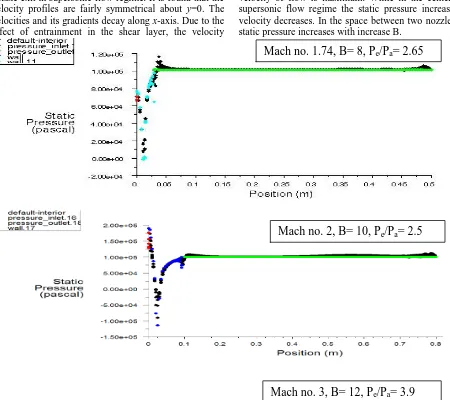
component along x-axis of the twin jets at exit Mach numbers (Me )1.74, 2 and 3, Dimensionless spacing (B)= 8, 10 and 12 and at different pressure ratio are shown in Fig.5.1. From the contours of velocity magnitude, it observed that the maximum velocity just before the nozzle exit in supersonic flow regime. It is found that the velocity profiles are fairly symmetrical about y=0. The velocities and its gradients decay along x-axis. Due to the effect of entrainment in the shear layer, the velocity
between two jets increases with x-axis. At the same time, the width of twin jets was found to increase.
Pressure:
From Fig.5.2, it observed that the static pressure inside the nozzle is minimum and it decreases with velocity increment, i.e, minimum just before the nozzle exit where velocity of flow is maximum. While in the center line supersonic flow regime the static pressure increases as velocity decreases. In the space between two nozzles the static pressure increases with increase B.
Mach no. 3, B= 12, P
e/P
a= 3.9
Mach no. 1.74, B= 8, P
e/P
a= 2.65
Mach no. 2, B= 10, P
e/P
a= 2.5
Copyright © 2012 CTTS.IN, All right reserved Fig. 5.2, X-Y Plots of Static Pressure (pascal)
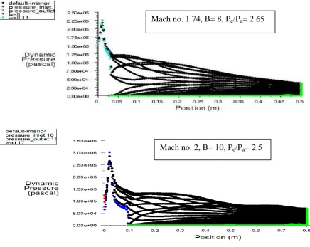
From Fig. 5.3, It observed that the dynamic pressure increases with increase the Mach number, where the velocity magnitude is
maximum dynamic pressure is also. It decreases with the center line of the supersonic flow as it passes the nozzle exit.
Mach no. 1.74, B= 8, P
e/P
a= 2.65
Copyright © 2012 CTTS.IN, All right reserved
Fig.5.3, X-Y Plots of the Dynamic Pressure (pascal)
Turbulence:
The jet is designed for streamline flow and hence the intensity of turbulence is less inside nozzle as compared to flow regime. From Fig. 5.4, it observed that the turbulence intensity has high value at nozzle exit. This is because of the eddy creation and reversal of flow at the base region of circular duct. Further downstream, as flow
gets agitated and the turbulence intensity increases. The maximum attained at outer shock shell near the nozzle exit and beyond which the turbulent intensity steadily decreases. It increases in between the space with increase the space between two nozzles and decreases with decrease the space between jets.
Fig. 5.4, Contours of the Turbulence Intensity (%)
Mach no. 3, B= 12, P
e/P
a= 3.9
Mach no. 1.74, B= 8, P
e/P
a= 2.65
Mach no. 2, B= 10, P
e/P
a= 2.5
Copyright © 2012 CTTS.IN, All right reserved
CONCLUSION
FLUENT analysis was carried out to investigate the flow field of the twin jets. The flow behaviors were measured to assist in understanding the change in the flow. The effects of Mach numbers (Me), pressure ratio (Pe/Pa) and the spacing (B) between two jets on the flow field along the flow and lateral directions were examined. The conclusions are drawn as follows:
It is seen that increase in jet Mach number (Me ) results in increase of the shock cell length, ie, the Mach disc shifts downstream with increase of Me. Further, the Mach disc diameter also increases with increasing Mach number, as expected. It is seen that both Me and Pe/Pa have similar effect on the jet width. In general, the jet width increases with increase of both Me and Pe/Pa. The distance where the inter boundaries coalesce, the jets in twin jet behave as single jet.
In the flow direction, the twin jet is clearly separated near the nozzle exits. Away from this region, the two jets interact, and then the twin jet mix and merge to appear as a single jet. The velocity and turbulent energy profiles are fairly symmetrical around the centre line of the twin jets for various Mach number and pressure ratio and the spacing between the two nozzles. The velocities between the two jets change along the lateral direction. The interference between two and four jets increases with increase of L.
The stronger the interference is, the larger the Reynolds shear stress and turbulent energy are.
The interference between the twin jet is increases as the spacing between two nozzles decrease. Furthermore the width of the twin jet spreads linearly downstream and grows with B. The merging length of the two jets can be increased either by reducing B or increasing Mach number. The results are in good agreement with the results obtained by the other techniques.
REFERENCE
[1] Zou Yue, „Air jet Velocity Decay in Ventilation Application‟, ISRN KTH/IT/M48SE, August, 1999.
[2] Tanner, M., „Base cavities at angles of incidence‟,
AIAA Journal, Vol. 26, No. 3, 1988, p. 374-377. [3] Vishwanath P.R. and Patil, S.R., „Effectiveness of
passive devices for axi symmetric base drag reduction at Mach 2‟, Journal of Spacecraft, May-June 1990, p. 234
[4] Kruiswyk, R.W and Dutton. J. C., „Effect of base cavity on subsonic near wake flow‟, AIAA Journal, Vol. 28, No. 11, 1990, p. 1885-1895.
[5] Rathakrishnan, E., „Effect of ribs on suddenly expanded flows‟, AIAA Journal, Vol. 39, No. 7, 2001, p.1402-1404.
[6] Pandey, K.M., and Rathakrishnan E., „Influence of cavities on flow development in sudden expansion‟, International Journal of Turbo and Jet Engines, Vol. 23, 2006, p. 97- 112.
[7] Pandey, K.M., and Rathakrishnan E., „Annular cavities for Base flow control‟, International Journal of Turbo and Jet Engines, Vol. 23, 2006, p. 113- 127.
[8] Pandey K. M., S. A. Khan and Rathakrishnan. E., „Passive control of base flows‟, Proceedings of the National Seminar on Recent Advances in Experimental Mechanics, Dept of Aerospace Engg, IIT Kanpur, Mar 15-16, 2000, ISBN – 81-7764-020-8, Allied Publications Ltd, New Delhi, India 2000 p. 57-71.
[9] B. Bouderah, A. Gasmi and H. Serguine, „Zero Gravity of Free-Surface Jet Flow‟, International Mathematical Forum, 2007, p. 3273 – 3277. [10] Katerina Horakova and Karel Frana, „Acoustics of
Jet Flow‟, Journal of applied science in the thermodynamics and fluid mechanics, Vol. 1, No. 1/2007, ISSN 1802-388.
[11] Yin Zhao-qin, „Experimental Study on The Flow Field Characteristics in the Mixing Region of Twin Jets‟, Science Direct , journal of Hydrodynamics, Ser.B, 2007, p. 309-313
[12] J.R. Berg, S.J. Ormiston, H.M. Soliman, „Prediction of the flow structure in a turbulent rectangular free jet‟, International Communications in Heat and Mass Transfer 33,
2006, p.552–563
[13] E. Rathakrishnan, „A Numerical Approach to Single and Twin Supersonic Jet Flows‟, IE (I) Journal AS, January, 2004, p. 32-34
[14] Virendra Kumar and K.M. Pandey, “Studies on supersonic free jet flow: a numerical analysis with fluent software” National Conference on Advances in Mechanical engineering. DBIT, Bangalore,
March 30-31, 2009, p. 72-76.
[15] K.M.Pandey and Virendra Kumar, CFD analysis of twin jet flow at Mach 1.74 with fluent software,, International Journal of Environmental Science and Development, Vol. 1, No. 3, December 2010, PP.423-428., ISSN: 2010-0264 , published by IACSIT, International Association for Computer Science and Information Technology, Singapore. [16] K.M.Pandey and Virendra Kumar, CFD Analysis