Simulation of AES Encryption and Decryption
Algorithm with Parallel Data Execution
Rajani Gupta
Deptt of Electronics and Communication, Sri Satya Sai Institute of
Science and Technology, Sehore M.P. India,[email protected]
Prof. Jai karan Singh
Deptt of Electronics and Communication, Sri Satya Sai Institute of
Science and Technology, Sehore M.P. India,[email protected]
Prof. Mukesh Tiwari
Deptt of Electronics and Communication, Sri Satya Sai Institute of
Science and Technology, Sehore M.P. India, [email protected]
Abstract - Advanced Encryption Standard (AES), has received significant interest over the past decade due to its performance and security level. Many hardware implementations have been proposed. In most of the previous works sub bytes and inverse sub bytes are implemented using lookup table method and using same key at time in parallel process. This performed less time for complete this process. This paper proposes a high-throughput implementation of AES (Advanced Encryption Standard) supporting encryption and decryption with 128-bit cipher key
Keywords - Advanced Encryption Standard (AES), Architecture of AES.
I. I
NTRODUCTIONCryptography is playing an important role in the security of data transmission in various environments in which high performance, low power consumption are key requirements. As Advanced Encryption Standard (AES) is a standardized encryption algorithm and considered secure, it was accepted as a Federal Information Processing Standards (FIPS) in November 2001 by National institute of Standards and Technology (NIST) [1]. In this paper we present an Application Specific Integrated Circuit (ASIC)[7]AES encryption and decryption core suited for high throughput devices. To achieve higher throughput, we should use more hardware resource. Some methods paid more attention to consuming time, and some methods paid more attention to increase the throughput. In this paper, we adopted reconfiguration to achieve a higher throughput. This paper is organized as follows. Section II, The AES algorithm is briefly presented. Section III, the detailed architecture optimizations are presented. Section IV the performance of our design. Section V compared with previous work, gives the discussions and conclusions.
II. T
HEAES
A
LGORITHMAES, also known as Rijndael, is the most popular algorithm used in symmetric key cryptography. AES operates on a 4×4 array of bytes termed the State. For encryption, it implements a round function 10, 12, 14 times (depends on the key length). The encryption and decryption flow of AES algorithm. our transformations including sub bytes, Row shift, Mix column and Key-generation are performed in the encryption process, and
the other four inverse transformations are performed in the decryption process. A separate Key-generation unit is used to generate keys for each round of AES algorithm and saved in the specific register. In order to simplify the hardware implementation and support both of encryption and decryption, AES encryption is an efficient scheme for software implementation. As compare to software implementation, hardware implementation provides greater physical security and higher speed. Hardware implementation is useful in wireless security like military communication and mobile telephony where there is a greater emphasis on the speed of communication. Most of the work has been presented on hardware implementation of AES using FPGA .This paper presents efficient software design simulation & implementation of AES and describes performance comparison of Rijndael algorithm based on execution clock criteria and hardware resource utilization.
III. E
NCODERP
ROCESSThe Encryption and decryption process consists of a number of different transformations applied consecutively over the data block bits, In a fixed number of iterations, called rounds. The encryption process has different stages, like as sub byte, row shift, mix column, and key generation. The encoder requires 10 rounds to complete the process. These inputs are sequentially applied in different rounds. The number of rounds depends on the length of the key used for the encryption process. For key length of 128 bits, the number of rounds required are10. (Nr = 10).
The four different transformations are described in detail below.
Sub Bytes Transformation
It is a non-linear substitution of bytes that operates independently on each byte of the State using a substitution table (S box). In this sub bytes step the data in the plain text is substituted by some pre-defined values from a substitution box. The substitution box which is used commonly is Rinjdael substitution box. The substitution box is invertible.
Shift Rows Transformation
4×4 matrix is shifted to left r bits and r varies with the rows of the matrix(r=0 for row1, r=1 for row2, r=2 for row3, r=3 for row 4). This process is illustrated in fig 2.
This has the effect of moving positions of lower positions in the row, while the lowest bytes wrap around to the top of the row.
Fig. 1. Row shift operation
Mix Columns Transformation
This transformation operates on the State column-by-column, each column as a four-term polynomial. The columns are considered as polynomials over Galois Field (28) and multiplied by modulo x4 + 1 with a fixed polynomial a(x) = {03} x3+ {01} x2+ {02} x.
Add Round Key Transformation
In this transformation, a Round Key is added to the State by a simple Bitwise XOR operation. Each Round Key consists of Nb words from the key expansion. Those Nb words are each added into the columns of the State. Key Addition is the same for the decryption process. In the add round key step the 128 bit data is xored with the sub key of the current round using the key expansion operation. The add round key is used in two different places one during the start that is when round r=0 and then during the other rounds that is when 1 ≤ round≤ Nr, where Nr is the maximum number of rounds. The formula to perform the add round key is S’(x) = S(x) R(x) where S’(x) – state after adding round key ,S(x) – state before adding round key and R(x) – round key. Describe in following figure. 2.
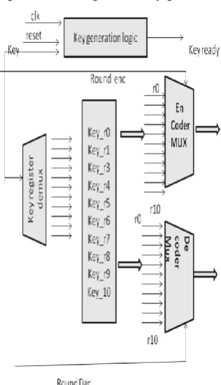
Key generation
Each round key is a 4-word (128-bit) register generated as a product of the previous round key, a constant that changes each round, and a series of S-Box lookups for each 32-bit word of the key. The Key schedule Expansion generates a total of Nb (Nr + 1) words. We have to used the different blocks designing of AES .it consist of encoder block and decoder block, that can be able to generate the10 different key and its save in different resistors .then we used these key are required in different stages. when input data are applied the key generation block and also clock pulse and output of initial key are used to different operation, these key are required the input of the encoder ,but output of encoder is required to the as a input of decoder also used I the enable input. we have get the result and the analysis of the output wave form.
Describe in following figure.
Fig. 2. Block Diagram of Key generation
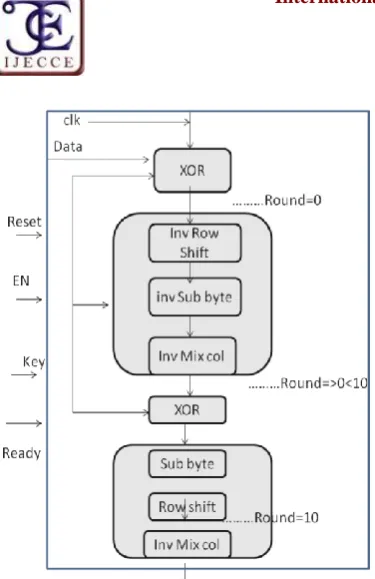
Fig. 3. Block Diagram of Encrypt process
Decoder Process
The decryption process is direct inverse of the encryption process. All the transformations applied inencryption process are inversely applied to this process. Hence the last round values of both the data and key are first round inputs for the decryption process and follows in decreasing order.
Fig. 3. block diagram of Decryption Process
IV. E
XPERIMENTALR
ESULTSExperimental Results
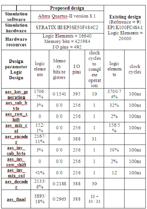
All the results are based on simulations from the Altera Quarts II 8.1 tools, using Test Bench Waveform Generator.All the individual transformation of both encryption and decryption are simulated using CPLD STRATIX III Vertex family and EP3SE50F780C2 device. Each program is tested with some of the sample vectors provided by FIPS[4]
Simulation Results
The waveforms generated by the 128-bit byte substitution transformation. The inputs are clock of 10ns time period, Active High reset, and128-bit state as a standard logic vector, whose output is128-bit S-box lookup table substitution operation is complete 1 clock cycles.
Fig. 4. Simulation Waveforms of 128-bit Byte Substitution
The waveforms generated by the 128-bit shift row transformation. The inputs are clock of 10ns time period,
Active High reset, and 128-bit state as a standard logic vector. this operation is complete 1 clock cycles.
Fig. 5. Simulation Waveforms of Shift Row Transformation
The waveforms generated by the 128-bit Mix Columns transformation. The inputs are clock of 10ns time period, Active High reset, and 128-bit state. This operation is complete 1 clock cycles.
Fig. 6. Simulation Waveforms of Mix Column Transformation
The waveforms generated by the 128-bit Add Round Key operation. The inputs are clock of 10ns time period, 128-bit key and 128-bit state as a standard logic vector, whose output is the 128-bit which is EXOR operation of 128-bit state and 128-bit key. This operation is complete 10 clock cycles
Encryption Process (Cipher):
AES block length/Plane Text = 128bits (Nb=4)
Key length = 128 bits (Nk =4); No. of Rounds = 10(Nr =10)
Plane Text : 00112233445566778899aabbccddeeff Key : 000102030405060708090a0b0c0d0e0f
Output/CipherText:69c4e0d86a7b0430d8cdb78070b4c55a
The waveforms generated by the 128-bit complete encryption Process. The inputs are clock1 & clock2, Active High reset, 4-bit round, and 128-bit state & key as a standard logic vectors, whose output is the 128-bit cipher (encrypted) data. This operation is complete 31 clock cycles.
Fig. 8. Simulation Waveforms of Final Round of Encryption Process
Decryption Process (Inverse Cipher):
AES block length/Cipher Text = 128bits (Nb=4) Key length = 128 bits (Nk =4); No of Rounds = 10(Nr =10)
Input /Cipher Text: 69c4e0d86a7b0430d8cdb78070b4c55a Key: 000102030405060708090a0b0c0d0e0f
Output/Plain Text: 00112233445566778899aabbccddeeff The waveforms generated by the 128-bit complete decryption Process. The inputs are clock1 & clock2, Active High reset, 4-bit round, and 128-bit state & key as standard logic vectors, whose output is the 128-bit plain text (decrypted data).this operation is complete 30 clock cycles
Fig. 9. Simulation Waveforms of Final Round of Decryption Process
V. C
OMPARISONW
ITHO
THERW
ORKSC
OMPARISONR
ESULT/C
ONCLUSIONThe Advanced Encryption Standard-Rijndael algorithm is an iterative private key symmetric block cipher that can process data blocks of 128 bits through the use of cipher keys with lengths of 128 bits. Optimized and Synthesizable VHDL code is developed for the implementation of both 128 bit data encryption and decryption process & description is verified using ISE 8.1 functional simulator from Altera.
In case of alternate encryption-decryption sequential operation, proposed final aes design will require 71 (key generation=10, encryption31, decryption = 30) clock pulses for first time alternate sequential operation. Afterwards, for no change in the key, it will require 61 clock pulses for its alternate sequential.
In this paper, the individual components of the complete design are functionally simulated for verifying the desired logic performance at a functional clock time-period of 10ns.Successful Timing simulation is also carried out at individual component level with clock time period of 50ns.
R
EFERENCES[1] NATIONAL INSTITUTE OF STANDARDS AND
TECHNOLOGY (NIST). Advanced Encryption Standard (AES), 2001.
[2] J. Nechvatal et. al., Report on the development of Advanced Encryption Standard, NIST publication, Oct 2, 2000.
[3] FIPS 197, “ADVANCED ENCRYPTION STANDARD (AES)”,
November 26, 2001
[4] Rudra A, etal. EFFICIENT IMPLEMENTATION OF
RIJNDAEL ENCRYPTION WITH COMPOSITE FIELD ARITHMETIC [C]. 2001, 1752188.
[5] Y. Huang,Y. Lin, K. Hung and K. Lin, "EFFICIENT
IMPLEMENTATION OF AES IP," CIRCUITS AND
SYSTEMS 2006, APCCAS IEEE Conference, pp.1418-1421, 2006.
[6] Xinmiao Zhang, Parhi K K. HIGH-SPEED VLSI
ARCHITECTURES FOR THE AES ALGORITHM.VERY LARGE SCALE
Integration (VLSI) Systems, IEEE transactions on Volume12,Issueg,SePt. 2004 Page(s) :957-967.
[7] K. Gaj and P. Chodowiec, “FAST IMPLEMENTATION AND FAIR COMPARISON OF THE FINAL CANDIDATES FOR ADVANCED ENCRYPTION STANDARD USING FIELD PROGRAMMABLE GATE ARRAYS,” Proc. RSA Security Conf., Apr. 2001
[8] A LOW-COST RECONFIGURABLE ARCHITECTURE FOR
AES ALGORITHM Yibo Fan, Takeshi Ikenaga, Yukiyasu Tsunoo, and Satoshi Go to World Academy of Science, Engineering and Technology 41 2008,
[9] EFFICIENT HARDWARE DESIGN AND
IMPLEMENTATION OF AES CRYPTOSYSTEM, Pravin B. Ghewari1 Mrs. Jaymala K. Patil1 Amit B. Chougule2, International Journal of Engineering Science and Technology Vol. 2(3), 2010, 213-219
[10] ALGORITHMS FOR IDENTIFICATION KEY GENERATION
AND OPTIMIZATION WITH APPLICATION TO YEAST Identification Alan P. Reynolds1, Jo L. Dicks2, Ian N. Roberts3, Jan-Jap Wesselink1,Beatriz de la Iglesia1, Vincent Robert4, Teun Boekhout4, and Victor J. Rayward-Smith1, S. Cagnoni et al. (Eds.): EvoWorkshops 2003, LNCS 2611, pp. 107–118, 2003
[11] MATRIX BASED KEY GENERATION TO ENHANCE KEY
AVALANCHE IN ADVANCED ENCRYPTION STANDARD Paul A.J. Mythili P. Paulose Jacob K. Cochin University of Science and Technology, Kochi, Kerala, India.
International Conference on VLSI, Communication &
Instrumentation (ICVCI) 2011 Proceedings published by International Journal of Computer Applications® (IJCA) .
[12] DESIGN OF AES ALGORITHM USING FPGA. Atul M. Borkar Student [ M-Tech (VLSI) ] International Conference on Advanced Computing, Communication and Networks, Department of Electronics Engineering Maharashtra, India.
A
UTHOR’
SP
ROFILERajani Gupta
M.Tech. Student (VLSI) Design in SSSIST, Sehore. I have complete graduation in PCST Bhopal in 2007 Batch in RGPV Bhopal, MP. India.
Prof. Jai Karan Singh
M.Tech. in VLSI designs in RGPV Bhopal M.P., India