Amirkabir University of Technology (Tehran Polytechnic)
Vol. 46, No. 1, Spring 2014, pp. 1- 9
Amirkabir International Journal of Science& Research (Electrical & Electronics Engineering)
AIJ-EEE) )
٭
Corresponding Author, Email: [email protected]
Optimal Design of Single-Phase Induction Motor Using
MPSO and FEM
B. Farhadi
1, S.H. Shahalami
2*and E. Fallah Choolabi
31-MSc. Student, Department of Electrical Engineering, Faculty of Engineering, University of Guilan, Rasht, Iran 2-Assistant Professor, Department of Electrical Engineering, Faculty of Engineering, University of Guilan, Rasht, Iran
3-Assistant Professor, Department of Electrical Engineering,Faculty of Engineering, University of Guilan, Rasht, Iran
ABSTRACT
In this paper, a new approach is proposed for the optimum design of single-phase induction motor. By
using the classical design equations and the evolutionary algorithms such as Genetic Algorithms (GA),
Particle Swarm Optimization (PSO) and Modified Particle Swarm Optimization (MPSO), a Single Phase
Induction Motor (SPIM) was designed with the maximum efficiency. The Finite Element Method (FEM)
was used to achieve an accurate model of the motor. This model was used to validate the optimum design
instead of implementing it practically that would be expensive. Results show that the efficiency of the motor
designed by MPSO is higher compared to the ones designed by other methods. So this algorithm can be
proposed as an appropriate tool in design of single-phase induction motors.
KEYWORDS
1-INTRODUCTION
The Single Phase Induction Motors (SPIMs) are used in wide range of home and industry appliances, however, the efficiency of these motors are typically low and they are improper comparing to the three-phase induction motors. Due to the wide range of applications, any attempt to improve their efficiency leads to a significant reduction in the total energy consumption.
For the last decade, many attempts have been made on the optimization of the single-phase induction motors design. Initially, the classical techniques were used for optimizing the motors design. In [1] and [2] numerical optimization methods including Boundary-Search and Han-Powell method has have been compared with each other. The weakness of these methods is that if the convergence string does not include the optimum point, the optimization will not occur. In Boundary-Search method the chance of convergence is reduced by increasing the number of variables so this method is not appropriate for SPIM design that is an optimization problem with so many variables. Han-Powell method has the problem of trapping in local optimum points. Davidon-Fletcher and Steepest-descent are time-consuming methods and the improvement observed in the objective function between successive iterations is very small [3]. Another disadvantage of the classical methods is their need of the model linearization that reduces the optimization accuracy.
With the development of the evolutionary algorithms, using these methods in solving nonlinear optimization problems becomes more convenient. Evolutionary optimization techniques are suitable for the design problem of the induction motors. With this approach, any desired conditions can easily be included in the optimization problem. Random search algorithms such as Genetic Algorithm (GA) and Neural Networks (NN) have been used for induction motors optimization problem [4], however recent researche has shown some difficulties of the GA. Premature convergence of Genetic Algorithm reduces the search capability and increases the possibility of trapping in local optimum points [5].
Particle Swarm Optimization (PSO) was introduced by Kenedy and Eberhart [6-8]. The idea of this algorithm is taken from the flying of the birds and swimming of the fishes and their social life. The performance of PSO greatly depends on the selection of its parameters and if they are not selected properly the optimization process may trap in local optimum points [9-10]. In the Modified PSO (MPSO), the parameters such as inertia weight and acceleration factors are updated on the basis of the objective function. By adapting the PSO parameters, it not only avoids the premature convergence but also explores and exploits the promising regions in the search space successfully [11].
Since the last decade, many attempts have been made on the optimization of the single-phase induction motors design [1-4, 12-19]. In this paper, MPSO was used to achieve an optimum design of the SPIM. Motor efficiency was selected as the objective function and some limitations are imposed on the performance
characteristics of the motor. The proposed method was used to optimize the design of a 1hp motor. The results show that the motor designed by MPSO has greater efficiency compared to the motors designed by other methods such as conventional method, GA and PSO. To validate the design process, one method is to manufacture the designed motor and compare its outputs with the ones predicted in the design process. This method of validation would be expensive. Another way of validation is using the Finite Element Method (FEM) to obtain an accurate model of the motor. In this paper the second way was employed to validate the results of the design methods.
2-SPIMOPTIMIZATIONPROBLEM
2-1- DEFINITION OF THE PROBLEM
Optimization can be represented as finding the variables X=[x1 x2 ... xn] that maximizes an objective
function f(X), subject to some constraints in of G(X)≤0.
Like other electrical machines, SPIMs are designed to meet certain specifications. Relationships and equations which are used in design of SPIM can be divided into three parts, geometrical, electrical and magnetic equations. Most of them are empirical and have been derived from experiments [12]. The geometrical parameters of the stator and rotor are shown in Figs. 1 and 2.
Fig.1. Geometrical parameters of the stator
Fig.2. Geometrical parameters of the rotor
2-2- DESIGN VARIABLES
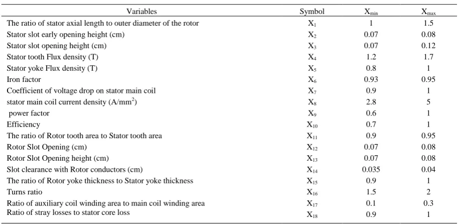
In this paper 18 parameters, which are listed in Table 1, are considered as the design variables of SPIM. Initial values of these parameters are obtained from the conventional method of the SPIM design [12].
x6, x7 and x14 are often dictated by the
TABLE 1. DESIGN VARIABLES
Variables Symbol Xmin Xmax
The ratio of stator axial length to outer diameter of the rotor X1 1 1.5
Stator slot early opening height (cm) X2 0.07 0.08
Stator slot opening height (cm) X3 0.07 0.12
Stator tooth Flux density (T) X4 1.2 1.7
Stator yoke Flux density (T) X5 0.8 1
Iron factor X6 0.93 0.95
Coefficient of voltage drop on stator main coil X7 0.9 1
stator main coil current density (A/mm2) X
8 2.8 5
power factor X9 0.6 1
Efficiency X10 0.7 1
The ratio of Rotor tooth area to Stator tooth area X11 0.9 0.95
Rotor Slot Opening (cm) X12 0.07 0.08
Rotor Slot Opening height (cm) X13 0.07 0.08
Slot clearance with Rotor conductors (cm) X14 0.035 0.04
The ratio of Rotor yoke thickness to Stator yoke thickness X15 0.9 1
Turns ratio X16 1.5 2
Ratio of auxiliary coil winding area to main coil winding area X17 0.1 0.3
Ratio of stray losses to stator core loss X18 0.9 1
In the beginning of the design process, the initial values of the power factor (x9) and the efficiency (x10) are
selected between the intervals that are given in the Table 1. After completing the design, their new values are recalculated and the design process is repeated until their values converge.
The sum of the mechanical loss, stator auxiliary winding copper loss and rotor core loss is called the Stray loss (x18). It depends on the duty cycle of the motor, the
exit time of the auxiliary winding, type of the fan, cooling method and other ad joint equipments. In the design process, stray loss is assumed to be a percent of the stator core loss. According to the obtained amount of x18, the
exit time of the auxiliary winding, type of bearings, lubrication method and the type of the cooling fan can be identified.
2-3- DESIGN CONSTRAINTS
The four important motor performance indices are chosen as the design constraints. These are: Power factor (g1), starting to full load current ratio (g2), Starting to full
load torque ratio (g3) and temperature rise (g4).
2-4- OBJECTIVE FUNCTION
In this study, the motor efficiency is considered as the objective function:
(1)
η is the efficiency, Pout is the output power and ∆P is
the motor power losses.
3-CONVENTIONALPSOALGORITHM
Like the other evolutionary algorithms, the PSO algorithm also begins with a random population of the individuals. Each particle is an N vector with N members
that each member is one of the design parameters. Each particle will move in two directions:
- Towards the best position that each particle has been ever experienced.
- Towards the best position that all particles have been ever experienced.
The velocity of each particle and its new position are determined as follows:
( )
(
)
(2)
m is the number of particles in the swarm, k is the pointer of iterations, is the velocity of ith particle at the kth iteration, ω is the inertia, C1 and C2 are the
acceleration factors, rand1 and rand2 are random numbers between 0 and 1, is the personal best of the ith particle, gbest is the global best of the group and is the current position of the ith particle at the kth
iteration.
Particle inertia coefficient is adjusted according to the following equation:
(3)
iter is the current iteration number, itermax is the maximum iteration number, max and min are the
4-MPSOALGORIYHM
In the optimization algorithms, there are two abilities that are important; Exploration and Exploitation. Exploration is the ability of random search all around the space to find the points which maximize the objective function and the Exploitation is the ability of local search around the optimum points to modify them. All the optimization algorithms are written in order to have high Exploration in the beginning and high Exploitation in the continuous. Algorithms that are able to do this can avoid from being trapped in the local optimum points.
In the PSO algorithm, high value of ω leads to the high Exploration and small values of ω leads to high Exploitation. Moreover, large values of C1 and C2 help
the Exploration and small values of them help the Exploitation. In the MPSO, to create a balance between Exploration and Exploitation these coefficients are modified based on the objective function:
(4) √ (5) √ (6)
ik is the inertia weight of ith population at the kth
iteration, Fpbestk-1 is the objective value of pbest at the (K
-1)th iteration, Fgbestk-1 is the objective value of gbest at (K
-1)th iteration, Fik-1 is the objective value of ith population at the (K-1)th iteration and C1,i
K
and C2,i K
are first and second acceleration factors for the ith population at the kth
iteration respectively.
The fitness function value can be computed as follows:
( ) { ( )
( )
(7)
Fmin is the objective function of the worst possible
solution among the population. CV(X) is the overall variation from constraints. CV(X) is written as follows:
CV(X) = max (0, g1(s) – g1(c)) + max (0, g2(s) – g2(c)) + max (0, g3(c) – g3(s)) + max (0, g4(s) – g4(c)) (8)
g1 to g4 are the constraints functions that are defined
in section 2.3 and s and c indicate the specified and computed values of the constraints [11] .
5-OPTIMIZATIONRESULTS
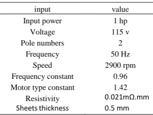
In The necessary codes of three algorithms, GA,PSO and MPSO, for SPIM optimization are written in the MATLAB software. The program input parameters were entered according to Table 2. Likewise, experimental
TABLE 2. PROGRAM INPUT PARAMETERS
input value
Input power 1 hp
Voltage 115 v
Pole numbers 2
Frequency 50 Hz
Speed 2900 rpm
Frequency constant 0.96
Motor type constant 1.42
Resistivity 0.021mΩ.mm
Sheetsthickness 0.5 mm
In optimization, population size and maximum iterations number are considered 30 and 100 respectively. Optimal solution was achieved in 20 executions of the programs. In MPSO, the parameters of inertia, ω, and acceleration factors, C1 and C2, are modified with respect
to the calculated value of the objective function. Changes of C1 and C2 with the number of iterations have been
shown in Fig.3 and Fig.4. During the initial iterations because of the small value of the objective function with respect to the gbest and pbest, C1 and C2 have higher
values. But, as the convergence reaches, all the population reach gbest and pbest. Thus, acceleration coefficients converge to the unit value.
Fig.3. Changes of C1 with respect to iterations
Fig.4. Changes of C with respect to iterations
0 10 20 30 40 50 60 70 80 90 100 1
1.05 1.1 1.15 1.2
Number of iterations
A c c e le ra ti o n f a c to r C 1
0 10 20 30 40 50 60 70 80 90 100
1 1.05 1.1 1.15 1.2 1.25 1.3
Number of iterations
Vol. 46, No. 1, Spring 2014
5
Changes of ω with the number of iterations have been shown in Fig. 5. Convergence characteristics of MPSO are compared with GA and PSO in Fig. 6. It is observed that updating the parameters of MPSO prevents premature convergence of this algorithm.
Fig.5. Changes of with respect to iterations
Fig.6. Changes of objective function (motor efficiency) with respect to iterations.
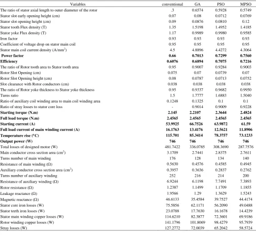
The results of the design for a typical 1hp motor are given in Table 3. The comparison shows that the efficiency of the motor obtained by using MPSO is a little greater than the efficiency obtained from other methods. In long time this greater value makes a considerable reduction in the total energy loss. This optimized motor has also better characteristics such as higher power factor, higher starting torque and lower rise in temperature.
In the simulation, it is convenient to use some assumptions that may cause the efficiency to be overestimated. Some example of these assumptions are as follows: Employing empirical curves for estimation of stator core loss and assuming that the stray loss (including mechanical loss, auxiliary winding cupper loss and rotor iron loss) is a percent of stator iron loss. Since these assumptions are the same for all designs, if we want to implement them practically, the best design in simulation will be the best in the implementation.
6-FINITE ELEMENT ANALYSIS
In this study, the FEM software, MAXWELL-2D was used to analyze the designs obtained through optimization algorithms.
The characteristics of the core such as flux density to ampere-turn curve, core loss to flux density curve and mass density are given in [12]. They were defined in the MAXWELL software and were assigned to the rotor and the stator cores. The meshes for the finite element analysis are shown in Fig. 7. The total number of meshes is 6232. As it shows, the number of meshes in the air gap region is higher than the rest of the model. The number of meshes for modeling the designs obtained through GA, PSO and MPSO are 6843, 5721 and 7504 respectively.
With appropriate settings of the program and executing it, the desired outputs were derived. Magnetic flux lines and flux density distribution are shown in Figs. 8 and 9 respectively. The curves of input current and torque versus speed, for the motors designed by conventional and MPSO methods are shown in Figs. 10 to 13.
Fig.7. The meshes of the FEM model of conventional design
Fig.8. Magnetic flux lines for the motor designed by MPSO
0 10 20 30 40 50 60 70 80 90 100
0 0.1 0.2 0.3 0.4 0.5 0.6 0.7 0.8
Number of iterations
In
e
rt
ia
w
e
ig
h
t
fa
c
to
r
0 10 20 30 40 50 60 70 80 90 100
0.65 0.66 0.67 0.68 0.69 0.7 0.71 0.72 0.73 0.74 0.75
iteration
F
it
n
e
s
s
V
a
lu
e
TABLE 3. RESULTS OF DESIGN A TYPICAL 1HP SPIM
Variables conventional GA PSO MPSO
The ratio of stator axial length to outer diameter of the rotor .3 0.6574 0.5928 0.5749
Stator slot early opening height (cm) 0.07 0.08 0.0712 0.0769
Stator slot opening height (cm) 0.09 0.0876 0.0810 0.12
Stator tooth Flux density (T) 1.35 1.5198 1.4952 1.4185
Stator yoke Flux density (T) 1.17 0.9989 0.9980 0.9585
Iron factor 0.93 0.93 0.93 0.93
Coefficient of voltage drop on stator main coil 0.95 0.95 0.95 0.95
Stator main coil current density (A/mm2) 4.5 4.8896 4.4272 4.3064
Power factor 0.66 0.7013 0.7299 0.7560
Efficiency 0.6076 0.6894 0.7075 0.7216
The ratio of Rotor tooth area to Stator tooth area 0.95 0.9007 0.9284 0.9003
Rotor Slot Opening (cm) 0.075 0.07 0.0739 0.07
Rotor Slot Opening height (cm) 0.08 0.0787 0.0713 0.0752
Slot clearance with Rotor conductors (cm) 0.038 0.038 0.038 0.038
The ratio of Rotor yoke thickness to Stator yoke thickness 0.95 0.9337 0.9682 0.9950
Turns ratio 1.5 1.7777 1.6883 1.5040
Ratio of auxiliary coil winding area to main coil winding area 0.1248 0.1325 0.1 0.1
Ratio of stray losses to stator core loss - 0.9014 0.9009 0.9228
Starting torque (N.m) 2.145 2.2107 2.3644 2.4824
Full load torque (N.m) 2.4565 2.4565 2.4565 2.4565
Starting current (A) 53.9925 66.7526 63.9872 61.59
Full load current of main winding current (A) 16.1763 13.4176 12.5621 11.8906
Temperature rise (C) 115.701 85.3414 78.3757 73.1233
Output power (W) 746 746 746 746
Total losses of designed motor (W) 481.7422 336.0785 308.3690 287.7576
Main conductor cross section area (cm2) 3.1709 2.7441 2.8375 2.7611
Turns number of main winding 176 128 134 140
Resistance of main winding () 0.5630 0.4576 0.4585 0.4945
Auxiliary conductor cross section area (cm2) 0.3957 0.3636 0.2837 0.2762
Turns number of auxiliary winding 252 216 214 200
Resistance of auxiliary winding () 6.9244 6.1198 7.7491 7.3893
Rotor resistance () 1.2387 1.1499 1.1709 1.1855
Leakage reactance () 1.9566 1.29 1.3629 1.5243
Magnetic reactance () 46.6133 35.4584 39.7527 44.4174
Stator core iron losses (W) 75.5856 62.1171 56.2090 49.0488
Stator teeth iron losses (W) 23.0788 17.7630 16.1678 14.4239
Stator main winding copper losses (W) 114.6210 82.3877 72.3601 69.9186
Rotor winding copper losses (W) 141.1796 101.8069 98.4279 95.7939
Stray losses (W) 127.2772 72.0039 65.2042 58.5724
Fig.9. Distribution of the flux density for the motor designed by MPSO
Vol. 46, No. 1, Spring 2014
7
Fig.11. input current versus speed for the motor designed byMPSO
Fig.12. Torque versus speed for the conventional design
Fig.13.Torque versus speed for the motor designed by MPSO
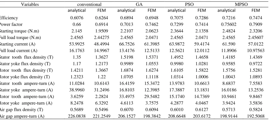
The motor was assumed to be the split-phase type, it is assumed that when the motor speed reaches %75 of the rated speed the auxiliary winding is cut out. The results of FEM analysis of the motors designed by conventional and MPSO methods are given in Figs. 14 and 15 respectively. Other numerical results obtained from FEM are compared with the analytical outputs of the design methods in Table4. The comparisons of the results show that the finite element analysis verifies the design methods with an acceptable accuracy. Moreover, it can be seen that all of the motors designed by GA, PSO and MPSO are superior with respect to the conventional design. Similarly, the finite element analysis demonstrates that MPSO is superior over the PSO and GA and this algorithm can be proposed as a suitable tool in design optimization of the SPIM.
Fig.14. Results of FEM analysis for the motor designed by conventional method
TABLE 4. COMPARISON OF FEM ANALYSIS AND OUTPUT OF DESIGN METHODS
Variables conventional GA PSO MPSO
analytical FEM analytical FEM analytical FEM analytical FEM
Efficiency 0.6076 0.6264 0.6894 0.6948 0.7075 0.7286 0.7216 0.7474
Power factor 0.66 0.6914 0.7013 0.7462 0.7299 0.7414 0.75602 0.7909
Starting torque (N.m) 2.145 1.9509 2.2107 2.0623 2.3644 2.1358 2.4824 2.3206
Full load torque (N.m) 2.4565 2.44275 2.4565 2.0471 2.4565 2.0471 2.4565 2.45607
Starting current (A) 53.9925 48.4994 66.7526 61.3985 63.9872 59.4174 61.590 57.0122
Full load current (A) 16.1763 14.9967 13.4176 12.5133 12.5621 12.0112 11.8906 10.97563
Stator tooth flux density (T) 1.35 1.3627 1.5198 1.5371 1.4952 1.4658 1.4185 1.4369
Stator yoke flux density (T) 1.17 1.2173 0.9989 1.0553 0.9980 1.0281 0.9585 0.9722
Rotor tooth flux density (T) 1.4211 1.3667 1.6874 1.6274 1.6105 1.5822 1.5756 1.5281
Rotor yoke flux density (T) 1.2323 1.22 1.0705 1.1118 1.0314 1.0006 1.0043 1.0893
Stator tooth ampere-turn (A) 11.0284 10.6143 16.4159 15.3472 13.9783 10.6613 8.6837 7.5583 Stator yoke ampere-turn (A) 38.9960 31.2496 16.8103 12.3985 17.3887 13.1831 16.0186 13.2536
Rotor tooth ampere-turn (A) 3.6259 2.2824 33.4975 29.5482 15.1740 14.7369 10.9461 9.8467
Rotor yoke ampere-turn (A) 8.2478 6.3292 4.6113 3.7575 4.2877 4.0467 3.9424 3.5836
Air gap flux density (T) 0.5689 0.5496 0.6070 0.6094 0.6010 0.6127 0.5713 0.5824
Air gap ampere-turn (A) 226.0838 221.2549 206.1527 198.3842 208.6648 203.6172 198.9144 192.5068
7-CONCLUSION
In conventional design method of SPIM some parameters are considered as empirical variables. In this paper, these parameters are selected as optimization variables and were determined by using GA, PSO and MPSO with the objective function of motor efficiency. PSO and MPSO are the same except that in MPSO the inertia and acceleration factors are updated on the basis of objective function. The results show that the motor efficiency obtained by these three optimization algorithms has been considerably increased compared to the conventional method. Moreover, the motor designed by MPSO has better performance characteristics than the one designed by GA and PSO.
In order to verify the results of the designed optimization methods, the Finite Element analysis was employed. FE analysis showed that the motor characteristics that were estimated by design methods have an acceptable accuracy. FE analysis confirmed that the motor efficiency for the motors designed by GA, PSO and MPSO are greater than the one designed by the conventional method. Moreover it confirms the superiority of the motor designed by MPSO over the GA and PSO. In fact the superiority of MPSO over the PSO is that it starts with good Exploration ability and by reducing the speed of particles, reaches a good Exploitation ability. The GA has the drawback of premature convergence and trapping in the local minimum. This fact is clearly shown in Fig. 6. So MPSO could be proposed as a suitable optimization tool for the design of single-phase induction motors.
In order to compare between these optimization methods, the characteristics of the core such as the flux density to ampere-turn curve, the core loss to the flux density curve and the mass density are assumed similar in all the methods.
Due to the unconsidered factors, It's obviously that the experimental results are different from the obtained results in this paper. Specially, in practice, the value of efficiency variable is smaller than that's obtained with different methods.
REFRENCES
[1] Mademlis, C., Ioskeridis, I., “Optimization of single phase induction motors part I: maximum energy efficiency control”, IEEE Transactions on Energy Conversion, vol. 20, no. 1, pp 187 - 195, March, 2005.
[2] Huang, H., Fuchs, E.F., Zak, Z., “Optimization Of Single Phase induction motor design part I: formulation of the optimization technique”, IEEE Transactions on Energy Conversion, vol. 3, no. 2, pp 349 - 356, Jun, 1988.
[3] Ramarathnam, R., Desai, B.G., Rao, V.S., “A comparative study of minimization techniques for optimization of induction motor design”, IEEE Transactions on Power Apparatus and Systems, vol. PAS-92 , no. 5, pp 1448 - 1454, 1973.
[4] Bhuvaneswari, R., Subramanian, S., “Optimization of Single-phase Induction Motor Design using Radial Basis Function Network”, Conference Proceeding of INDICON2005, pp 35 - 40, Dec, 2005.
[5] Eberhart, R.C., Kennedy, J., “A new optimizer using particle swarm optimization”, Proceedings of the Sixth International Symposium on Micro Machine and Human Science, pp 39-43, 1995. [6] Kennedy, J., Eberhart, R., “Particle Swarm
Vol. 46, No. 1, Spring 2014
9
International Conference on Neural Networks, vol. 4, pp 1942 - 1948, 1995.
[7] Shi, Y., Eberhart, R.C., “Empirical study of particle swarm Optimization”, Proceedings of the 1999 Congress on Evolutionary Computation, vol. 3, pp 1945-1950, Jul, 1999.
[8] Eberhart, R.C. Shi, Y., “Comparing inertia weights and constriction factors in particle swarm optimization”, Proceedings of the 2000 Congress on Evolutionary Computation, vol. 1, pp 84-88, Jul, 2000.
[9] Chaturvedi, K.T., Pandit, M., Srivastava, L. “Particle Swarm optimization with time varying acceleration coefficients for non-convex economic power dispatch”, International Journal of Electrical Power & Energy Systems, vol. 31, no. 6, pp 249-257, 2009.
[10] Sakthivel, V.P., Bhuvaneswari, R., Subramanian, S., “An improved particle swarm optimization for induction motor parameter determination”, International Journal of Computer Applications, vol. 1, no. 2, pp 62 - 67, 2010.
[11] Sakthivel, V.P., Subramanian, S., “Using MPSO algorithm to optimize three-phase squirrel cage”, Proceedings of the International Conference on Emerging Trends in Electrical and Computer Technology, pp 261-267, March, 2011.
[12] Mittle, V.N., Mittal, A. ., “Design of Electrical Machines”, 4th edition, 1996.
[13] Fuat Uler G., Mohammed O.A., Koh C.S., “Design optimization of electrical machines using genetic algorithms”, IEEE Trans. Magnetics , vol. 31 , no. 3 , pp 2008 - 2011 , 1995.
[14] Wieczorek J.P, O. Gol, Z. Michalewiez, “An evolutionary algorithm for the optimal design of induction motors”, IEEE Trans. Magnetics , vol. 34 , no. 6 , pp 3882 - 3887, 1998.
[15] Bellarmine G.T., Bhuvaneswari R., Subramanian S., “Radial basis function network based design optimization of induction motor” , Proceedings of IEEE SOUTHEASTCON2006, pp 75-80, 2006.
[16]. Bhuvaneswari R., Subramanian S., “Fuzzy logic approach to three phase induction motor design”, Proceedings of the International Conference on Computer Applications in Electrical Engineering Recent Advances - CERA-05 , pp 505-509, 2005.
[17] Bhuvaneswari R. Subramanian S.,
“Optimization of Single-phase Induction Motor Design using Rsdial Basis Function Network”, IEEE Indicon 2005 Conference, 2005.
[18] K.Y. Jang , K.S. Kim , K.B. Kim, J. Lee , “Design of Premium Efficiency Level Single Induction Motor by Parameter Analysis”, International Conference on Electrical Machines and Systems ICEMS, pp 1-4, 2009.