A COMPARATIVE STUDY OF FUZZY LOGIC CONTROLLERS
FOR BLDC MOTOR DRIVE
N. Jayamary Sujatha1 and M. Saravanan2
1Electronics and Communication Engineering, Universit, College of Engineering, Ramanathapuram, Tamilnadu, India
2Electrical and Electronics Engineering, Thiagarajar College of Engineering, Madurai, Tamilnadu, India
E-Mail: [email protected]
ABSTRACT
The development of high performance variable speed brushless dc motor drive is very important in all industrial applications. Generally, a high performance BLDC motor drive system must have good dynamic speed response, reference speed command tracking capability and load regulating response. Conventional controller such as PI, PID does not provide good dynamic response due to the problem of non-linearity, difficulty in the tuning of controller parameters. With the fast growing of intelligent controllers for precise motor speed control, fuzzy logic controllers are taken in this paper. This paper demonstrates a comparative study of PI, fuzzy logic, hybrid fuzzy PID controllers using MATLAB/SIMULINK environment.
Keywords: BLDC motor, fuzzy logic, PI, hybrid fuzzy PID controller, back EMFs, speed control.
1. INTRODUCTION
Brushless D.C (BLDC) synchronous motors have been used in various fields of industrial applications for their high power/weight, high torque, high efficiency, long operating life, noiseless operation, high speed ranges and ease of drive control [1]. Permanent Magnet Brushless DC (PMBLDC) motor is defined as a permanent magnet synchronous motor with a trapezoidal Back EMF waveform [2]. BLDC motors do not have brushes for commutation. They are electronically commutated [3]. For the variable speed applications of BLDC motor, Proportional, Integral and Derivative (PID) motor control is commonly used control [4].Because; it has simple design and ease of control. However, its performance depends on proportional, integral and derivative gains [5-6]. When the operating condition changes, the re-tuning process of control gains is necessary for dynamically minimize the total controller error. The various algorithms are used to find optimal PID controller parameters such as Genetic Algorithm (GA) and Particle Swarm Optimization (PSO) [7-10].Particle Swarm Optimization (PSO) and genetic algorithm (GA) is given based on population size, generation number, selection method, and crossover and mutation probabilities. There is no guarantee for finding optimal solutions for controllers within a finite amount of time. To overcome the problems in PID controller, fuzzy logic controller and hybrid fuzzy PID controllers can be designed for the speed control of BLDC motor. In this proposed research work, the speed control of BLDC motor was analyzed and its performance has been observed by using fuzzy logic controller and hybrid fuzzy PID [11-13].The simulation results of two methods are studied and compared with conventional PI controller by using MATLAB/SIMULINK computational software. The simulation results of proposed controllers are used to show the abilities and shortcomings of conventional PI controller.
2. CLOSED LOOP MODEL OF BLDC MOTOR
The BLDC motor drive system consists of permanent magnet synchronous motor fed by a three-phase inverter.Figure1 shows the overall closed loop system configuration of three phase BLDC motor drive.
Figure-1. Block diagram of PMBLDC drive.
power transistors to give the power to the two BLDC motor phases concurrently. Outer loop controls the speed of the motor by supplying regulating D.C power to three phase inverter with any one of the controllers.
Figure-1. Back EMF logic with hall sensor signals.
3. SPEED CONTROLLERS
A. Fuzzy logic controller
Fuzzy logic controller is a rule-based logic controller. Fuzzy logic controller designs the general behaviors of the control system in a linguistic manner by forming IF-THEN rules [14]. The fuzzy rules are in the form of no of statements. The general structure of fuzzy logic controller consists of four functional parts as shown in Figure-3. They are given as fuzzification, fuzzy rule-base, fuzzy inference engine and defuzzification. The design steps in fuzzy logic controller are i) Define the inputs and output variables ii) Define universe of discourse iii) Define fuzzy membership functions and fuzzy set rules. In this fuzzy logic controller structure, E (error) and IE (integrative error) are taken as two inputs and gives controlled output (u) to the BLDC motor. A fuzzy logic controller with a fuzzy rule viewer block is used to control the output of BLDC motor. Different membership functions for fuzzy variables are selected to control the output. Fuzzy Interference System (FIS) file is saved which includes all input and output membership functions and fuzzy rules.
Figure-3. General Fuzzy logic controller.
Fuzzy Associative Memories (FAM) in FLC is a transformation matrix which map no of fuzzy sets. A FAM consists of collection of IF-THEN rules. These rules are given in forty nine possible two inputs and single output FAM rules as illustrated in Table as shown in Figure-4. The fuzzy output is converted into real value as the crisp output by the process called defuzzification. Even though various defuzzification methods are available, the most preferred method is centroid. It can be easily implemented in all digital control systems with less computation time. Final crisp value is the control value for the applied voltage across the armature winding and hence the speed of the motor.
Figure-4. 7*7 Fuzzy rules FAM matrix.
Each universe of discourse can be divided into seven fuzzy sets as followings; [14] NB: Negative Big PB: Positive Big Z: Nearer Zero NM: Negative Medium PS: Positive Small PM: Positive Medium NS: Negative Small. Triangular membership functions are selected for NB, NM, NS, ZE, PS, PM and PB fuzzy sets. The fuzzy set rules are given by,
If error is NB and integrative of error is NB then output signal is NB
If error is NB and integrative of error is NM then output signal is NB
Finally, all forty-nine fuzzy rules are summarized in the form of a FAM matrix is given in the form of table as shown in Figure-4. MATLAB/Fuzzy Logic Toolbox and BLDC overall simulink block are combined into FIS file to simulate the result.
B. Hybrid fuzzy PID controller
Triangular membership functions are selected for NB, NM, NS, ZE, PS, PM and PB fuzzy sets [16]. The fuzzy rule matrix for computing the output Δu is given in table as shown in Figure-6. The simulation of speed control of trapezoidal back EMF BLDC motor drive for HFPIDC controller is done by using MATLAB/SIMULINK software package [13].
Figure-2. Block diagram of hybrid fuzzy PID.
Figure-3. Fuzzy rules matrix of hybrid fuzzy PID.
C. PI controller
The PID controller is the most common and very useful controller for any plant. In a plant the feedback loops are mainly controlled by the PID controller. The error signal is passed through the PID controller and plant then output signal is given as feedback signal to the set input signal. The proportional (P), integral (I), and derivative (D) control parameters are arranged in a cascade order which is shown in below Figure 7. PID controller gains are Kp, Ki and Kd will be varied either by
manual method or Ziegler Nichols method to get output response with less rise time and overshoot.
Figure-4. Basic PID controller module.
4. SIMULATION RESULTS
[image:3.612.320.536.462.687.2]The simulation of the BLDC motor is done by using MATLAB/SIMULINK technical computing software package [15]. Its speed and torque waveforms are analyzed. A PI controller and fuzzy controller have been employed for speed control of BLDC motor. Through the simulations of all controllers, it is confirmed that the proposed hybrid fuzzy PID and fuzzy logic controllers provide a good response to the successive changes in reference speed and load torque. The results obtained by simulation show the feasibility and ability of the proposed fuzzy controllers strategy. The HFPID and Fuzzy logic controllers provide more efficient speed control technique for BLDC motor with good dynamic response characteristics such as rise time, peak overshoot, steady state error and settling time. Moreover, it generates less speed and torque ripples.
Figure-5. No load performance of the fuzzy, conventional
Figure-6. No load performance of the fuzzy, conventional
PI and hybrid fuzzy PID controllers at reference speed of 3000 rpm.
Figure-7. The performance of fuzzy, hybrid fuzzy PID
and conventional PI controllers of BLDC motor on speed of 2000rpm with load changes from 0.2Nw-m
to 0.1Nw-m.
Figure-8. The performance of fuzzy, hybrid fuzzy PID
and conventional PI controllers of BLDC motor on speed of 3000rpm with load changes from
0.1Nw-m to 0.2Nw-m.
Figure-9. The load torque performance of hybrid fuzzy
Figure-10. The load torque performance of conventional
PIcontroller of BLDC motor on speed of 3000rpm with load changes from 0.1Nw-m to 0.3Nw-m.
Figure-11. The load torque performance of fuzzy
controller of BLDC motor on speed of 3000rpm with load changes from 0.1Nw-m to 0.3Nw-m.
Figure-12. The load torque performance of fuzzy,
conventional PI and hybrid fuzzy PID controllers of BLDC motor on speed of 3000rpm with load changes
from 0.1Nw-m to 0.3Nw-m in expanded view.
Figure-13. The stator current and back EMF waveforms
Figure-14. The stator current and back EMF waveforms
of conventional PI controller of BLDC motor on speed of 2000rpm.
Figure-15. The stator current and back EMF waveforms
of fuzzy controller of BLDC motor on speed of 2000rpm.
Figure-16. Fuzzy logic controller surface viewer.
Figure-17. Hybrid fuzzy PID controller surface viewer.
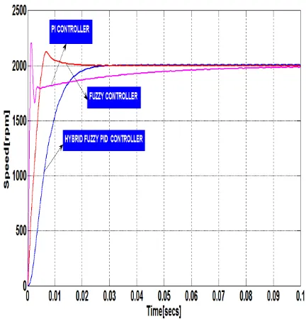
Figure-8 shows the performance of the fuzzy, conventional PI and hybrid fuzzy PID controllers of BLDC motor on reference speed of 2000rpm with no load condition. Figure-9 shows the performance of the fuzzy, conventional PI and hybrid fuzzy PID controller of BLDC motor on reference speed of 3000rpm with no load condition.
Figure-10 shows the performance of fuzzy, hybrid fuzzy PID and conventional PI controller of BLDC motor on speed of 2000rpm with load torque changes from 0.2Nw-m to 0.1Nw-m. Figure-11 shows the performance of fuzzy, hybrid fuzzy PID and conventional PI controller of BLDC motor on speed of 3000rpm load torque changes from 0.1Nw-m to 0.2Nw-m. Figure-12, Figure-13 and Figure-14 shows the load torque performance of fuzzy, conventional PI and hybrid fuzzy PID controllers of BLDC motor on speed of 2000rpm with load changes from 0.2Nw-m to 0.1Nw-m respectively. Figure 15 shows the load torque performance of fuzzy, conventional PI and hybrid fuzzy PID controllers of BLDC Motor on speed of 3000rpm with load torque changes from 0.1Nw-m to 0.3Nw-m.
Figure-19 shows surface viewer for fuzzy logic controller. Mamdani type of FIS is used. All membership functions of the FLC inputs, error (E) and integrative of error (IE) are given on the normalized domain form (-1, 1), (-5, 5). Output (u) is given as (-500, 500) normalized form.
Figure-20 shows surface viewer for hybrid fuzzy PID controller. Mamdani type of FIS is used. All membership functions of proposed HFPIDC inputs, error (E) and integrative of error (IE) are given on the
normalized domain form (-1, 1), (-1, 1). Output (u) is given as (0, 500) normalized form. The performance results of conventional PI, fuzzy and hybrid fuzzy PID controllers of BLDC motor is shown in 1 and Table-2. The performance parameters of rise time (TR), peak overshoot (rpm), settling time (ts), steady state error (%) speed ripples (%), torque ripples (%) of BLDC motor drive controllers are analyzed. From the performance results, hybrid fuzzy PID and fuzzy controllers have better control performance than the conventional PI controller.
Table-1. The performance results of conventional PI, fuzzy and hybrid fuzzy
PID controllers for 1000 rpm with no-load at 0.3secs.
Speed with load torque
1000 rpm with no-load
PI controller Fuzzy logic
controller
Hybrid Fuzzy PID controller
Rise time
(tr in secs) 0.036 0.0093 0.0319
Settling time
(ts in secs) 0.045 0.018 0.028
Peak overshoot
( %) 16.67 0.50 ---
Steady state
error (%) 0.3 0.15 0.2
Torque ripples
(%) 1.6 1.1 1.0
Speed ripples
(%) 0.2 0.1 0.1
Table-2. The performance results of conventional PI, fuzzy and hybrid fuzzy
PID controllers for 3000 rpm with no-load at 0.3secs.
Speed with load torque
3000 rpm with no-load
PI controller Fuzzy logic
controller
Hybrid Fuzzy PID controller
Rise time
(tr in secs) 0.016 1.582e-3 0.0123
Settling time
(ts in secs) 0.090 0.020 0.023
Peak overshoot
( %) 11.66 0.8667 1.33
Steady state
error (%) 0.270 0.0667 0.2667
Torque ripples
(%) 1.5 1.2 1.1
Speed ripples
Table-3. The performance results of conventional PI, fuzzy and hybrid fuzzy
PID controllers for 2000 rpmwith 0.3 Nw-m load at 0.3secs.
Speed with load torque
2000rpm with 0.3 Nw-m load
PI controller Fuzzy logic
controller
Hybrid Fuzzy PID controller
Rise time
(tr in secs) 0.0333 4.6e-3 0.0170
Settling time
(ts in secs) 0.155 0.115 0.120
Peak overshoot
( %) 10.60 7.0 ---
Steady state
error (%) 1.0 0.95 0.90
Torque ripples
(%) 23.0 18.60 17.50
Speed ripples
(%) 1.11 1.0 1.0
Table-4. The performance results of conventional PI, fuzzy and hybrid fuzzy
PID controller’s for3000 rpm with 0. 1 Nw-m load at 0.3secs.
Speed with load torque
3000rpm with 0. 1 Nw-m load
PI controller Fuzzy logic
controller
Hybrid Fuzzy PID controller
Rise time
(tr in secs) 0.015 2e-3 0.01
Settling time
(ts in secs) 0.10 0.03 0.035
Peak overshoot
( %) 11.67 0.933 1.30
Steady state
error (%) 0.24 0.06 0.23
Torque ripples
(%) 15.0 13.5 10.0
Speed ripples
(%) 0.533 0.50 0.50
From the results of analysis of controllers, it is clear that HFPID controller has to provide better results with less torque ripples compared to other controllers. But, FLC gives good speed response with less rise time and settling time than HFPID and PI controllers. Speed ripples for HFPIDC and FLC will be the same and less than PI controller.
5. CONCLUSIONS
This paper presents comparative simulation study of conventional PI, fuzzy and hybrid fuzzy PID controllers of three phases BLDC Motor. In conventional PI control, parameters of PI controller are fixed as the reference speed and torque changes. With the results of simulations, it is clear that the BLDC speed control using hybrid fuzzy PID and fuzzy logic controllers give better performance than the conventional PI controller. The motor speed response is better when the load is varied from low to high or high to low values.
APPENDIX A
Parameters of PID Controller Proportional gain K P = 16.61 Integral gain K I = 0.5
APPENDIX B
BLDC motor parameters
Rated speed: 3000 rpm Rated voltage: 300 V dc Number of poles: 2 Type of connection: star Self & Mutual inductance/phase: 8.5e-3H Moment of inertia: 2.26e-005 kg-m2
Voltage constant: 71.9215 V/rpm Rated Torque: 0.8 Nw-m
REFERENCES
[1] K.P.Pillay and R.Krishnan, “Modeling, simulation and analysis of permanent-magnet motor drives, part-II: the brushless DC motor drives”, IEEE Trans. on Industry Applications, vol. 25, pp. 274 279, March/April1989.
[2] Pragasen Pillay and Ramu Krishnan, “Application characteristics of permanent magnet synchronous and brushless dc motors for servo drives”, IEEE Transactions on Industry Applications, vol. 21, no. 5, pp.no-987-996, September/October 1991.
[3] C. C. Chan, J. 2. Jiang, W. Xia, and K. T. Chau, “Novel Wide Range Speed Control of Permanent Magnet Brushless Motor Drives”, IEEE Transactions on Power Electronics, vol. 10, No. 5, pp. no- 539-546, September 1995.
[4] Pramod Pal,TM Subhuman and Dr.Amit Ojha,” Simulation of brushless dc motor for performance analysis using MATLAB/SIMULINK environment”, International Journal on Recent and Innovation Trends in Computing and Communication, vol. 2, pp. 1564-1567,June 2014.
[5] R.G.Rajesh, C.Balaji,”Speed control of BLDC motor using PID controller”, International Journal of Advanced Research in Electrical, Electronics and Instrumentation Engineering, vol. 3, pp.2320-3765, April 2014.
[6] I. Topaloglu, F. Korkmaz, H. Mamur, R. Gurbuz, ”Closed-Loop Speed Control of PM-BLDC Motor Fed by Six Step Inverter and Effects of Inertia Changes for Desktop CNC Machine”, Elektronika Ir Elektrotechnika, vol. 19, no. 1,pp.no.7-10, 2013.
[7] Mehdi Nasri, Hossein Nezamabadi-pour and Malihe Maghfoori, ”A PSO-based optimum design of pid controller for a linear brushless dc motor”, International Journal of Electrical, Robotics, Electronics and Communications Engineering, vol. 1 no: 2, pp. 171-175, 2007.
[8] M.P.Prasanna Kumar, P. Devendra, R. Srinivasa Rao,Indranil Saaki,” Optimal tuning of PID controller for a linear brushless dc motor using particle swarm optimization technique”, Engineering Research and Applications, vol. 2, pp. 1416-1420, July-August 2012.
[9] S. Poonsawat and T. Kulworawanichpong,” Speed regulation of a small BLDC motor using genetic-based proportional control, “World Academy of Science, Engineering and Technology”, vol. 2, pp. 205-210. 2008.
[10] Andri Mirzal, Shinichiro Yoshii, Masashi Furukawa,” PID Parameters Optimization by Using Genetic Algorithm”, Graduate School of Information Science and Technology Hokkaido University Sapporo, Japan.
[11] R.Kandiban, R.Arulmozhiyal,” Design of adaptive fuzzy PID Controller for speed control of BLDC motor”,International Journal of Soft Computing and Engineering, vol. 2, pp. 386-391, March 2012.
[12] S.Thamizmani, S.Narasimman,” Design of Fuzzy PID Controller for Brushless DC Motor”, International Journal of Emerging Research in Management and Technology, vol.3, pp. 67-75, April 2014.
[13] C. Subba Rami Reddy, M. Surya kalavathi, ”Performance evaluation of Hybrid fuzzy logic controller for brushless dc motor drive” ,International Journal of Engineering Science and Technology, vol. 3, pp. 4750-4758, June 2011.
[14] N. Muruganantham, Dr.S. Palani,” Adaptive neuro-fuzzy inference system based controller for high performance bldc motor using soft switching inverter”, Journal of Theoretical and Applied Information Technology, vol. 49, pp. 929-939, March 2013.
[15] Matlab- (R2008a) - The language of technical computing, software package.