29 Trans. Phenom. Nano Micro Scales, 4(1): 29-35, Winter - Spring 2016 DOI: 10.7508/tpnms.2016.01.004
A numerical investigation of γ-Al
2O
3-water nanofluids heat transfer and pressure
drop in a shell and tube heat exchanger
P. Shahmohammadi1, H. Beiki1,*
1Department of Chemical Engineering, Quchan University of Advanced Technology, 67335-94771, Quchan ,I.R. Iran
Received 22 February 2015; revised 16 November 2015; accepted 21 November 2015; available online 5 January 2016
ABSTRACT: The effect of γ-Al2O3 nanoparticles on heat transfer rate, baffle spacing and pressure drop in the shell side of small shell and tube heat exchangers was investigated numerically under turbulent regime. γ-Al2O3-water nanofluids and pure water were used in the shell side and the tube side of heat exchangers, respectively. Since the properties of γ-Al2O3-water nanofluids were variable, they were defined using the user define function. The results revealed that heat transfer and pressure drop were increased with mass flow rate as well as baffle numbers. Adding nanoparticles to the based fluid did not have a significant effect on pressure drop in the shell side. The best heat transfer performance of heat exchangers was for γ-Al2O3-water 1 vol.% and higher nanoparticles concentration was not suitable. The suitable baffle spacing was 43.4% of the shell diameter, showing a good agreement with Bell-Delaware method.
KEYWORDS: Baffle spacing; CFD models; γ-Al2O3-water nanofluids; Shell and tube heat exchanger; User define function (UDF)
INTRODUCTION
Today, due to the high cost of energy, increasing environmental pollution and limitations in the use fossil fuels, energy consumption optimization in various industrial processes has become very important. One of the most widely-used equipment in various industries, such as petrochemical, oil and gas refinery, etc., are heat exchangers that can be used for heating or cooling fluids. Among them, shell and tube heat exchangers are one of the most common. So it is very essential to optimize these types of heat exchangers.
Baffles play an important role in shell and tube heat exchangers heat transfer by increasing the heat transfer coefficient.
One of the most effective methods used for enhancing the heat transfer coefficient in shell and tube heat exchangers has been the use of a baffle arrangement. But after the advent of nanofluids, which are stable suspensions containing nanometer sized particles, improvement in the thermal properties of fluids in the heat exchangers to enhance the heat transfer rate and energy consumption optimization has been considered too [1-6]. The vast majority of studies on the heat transfer of nanofluids have reported that heat transfer in nanofluids is increased with nanoparticles concentration [6-11]. Nanoparticels increase the thermal conductivity of nanofluids through which the overall heat transfer is increase. Heat transfer performance of heat exchangers can be improved by using nanofluids. The nanofluids can help to reduce the cost and size of the heat exchangers, and heating and cooling systems.
Lower baffle spacing leads to increased heat transfer rate, *Corresponding Author Email: [email protected]
Tel.: +989155095198
but the pressure drop of the shell side fluid is also increased due to the leakage, bypass and decreased flow area effects. So, for the maximum heat transfer and minimal pressure drop to take place, the optimum number of baffles should be chosen. The most important works in this field are limited to common fluids. The well-known Kern method is used to predict shell side pressure drop and heat transfer coefficient [12].
The first computation method, which is the analysis of the shell side flow, is related to Tinker [13]. But this method is very difficult. After a series of experiments, Bell– Delaware method was presented. In this method the effect of baffle leakage has been considered and it is suitable for hand calculations [14].
30 Nomenclature
Temperature T (K)
B Central baffle spacing (mm) U Overall heat transfer coefficient (W m-2 K-1)
Bc Baffle cut (%) v Velocity component (m s-1)
cp Specific heat capacity in constant pressure
(J kg-1 K-1) V
Velocity vector
De Equivalent diameter (mm) Greek Symbols
Do Tube outer diameter (mm) Viscous dissipation rate (m2 s-3)
Ds Shell diameter (mm) Kinetic energy of turbulent fluctuations per unit
mass
K Thermal conductivity (W m-1 K-1) Viscosity (kg m-1 s-1)
L Heat exchanger length (mm) Density (kg m-3)
Nb Number of Baffles Φ Nanoparticles volume fraction
Nt Number of tubes Subscripts
P Pressure (kPa) bf Base fluid
PT Pitch of tube (mm) nf Nanofluid
Q Heat transfer rate (kW) p Nanoparticles
rate and entropy generation of shell and tube heat exchanger with different baffle angles and segmental baffle was also investigated, revealing that cylindrical shape nanoparticles had the best performance in respect to the overall heat transfer coefficient and heat transfer rate among the other shapes for different baffle angles along with the segmental baffle [22].
Ghozatloo et al. [23] investigated convective heat transfer of graphene nanofluidsin a shell and tube heat exchanger under laminar regimes. They observed that adding 0.075 wt.%graphene to the base fluid increased the heat transfer coefficient compared to pure water [23].
Akhtari et al. [20] studied the heat transfer of α- Al2O3 -water nanofluids in two types of heat exchangers, double pipe and shell and tube heat exchangers, under laminar flow conditions. In their study, input flow rate for cold fluid was 90, 180 and 200 (lit/h), and for the hot fluid, it was 100, 200 and 300 (lit/h). Also, the concentration of nanoparticles was 0.2% and 0.5 vol.%. They observed that the heat transfer performance of both double pipe and shell and tube heat exchangers was increased with increasing the hot and cold volume flow rates, as well as the nanoparticle concentrations and nanofluids inlet temperature [20].
Baffle spacing is the most important parameter used in the design of shell and tube heat exchangers and there are a few CFD studies in this area, even for common fluids.
Baffle spacing can be variable, between 20% and 100% of the shells diameter. This was obtained by Taborek for single-phase shell-side flows with single segmental baffles [24]. Using computer software for the thermal design of shell and tube heat exchanger, which was working with various traditional fluids in the shell side, Mukherjee showed that the optimum baffle spacing of the shell and tube heat exchanger normally ranged from 0.3 to 0.6 times of the shell diameter [25]. By using the heat exchanger design handbook methods, Saffar-Avval and Damangir [26] optimized the baffle spacing and the number of sealing strips for all types of single-phase shell and tube heat
exchangers. They proved that pumping power was strongly dependent on the baffle spacing while the effect of sealing strips number on the pumping power and optimum heat transfer area was negligible [26]. Soltan et al. [27] studied the baffle spacing effect on heat transfer area and pressure drop. They determined the optimum distance of baffles for single phase E and J types of shell and tube heat exchangers [27]. Thermoeconomic analysis was also used to determine the optimum baffle spacing for a shell and tube heat exchanger. Eryener [28] demonstrated that thermoeconomic analysis was a powerful tool to determine the optimum ratio of baffle spacing in the shell and tube heat exchanger. Ozden and Tari numerically [29] investigated the baffle spacing and baffle cut dependencies of the heat transfer coefficient and the pressure drop by modeling a small heat exchanger. They also studied the difference between the results of Bell and CFD methods for water as the working fluid and different turbulence models in a commercial CFD package [29].
Heat transfer fluids in all above baffle spacing studies were common fluids such as water, oil, ethylene glycol, etc. Since the nanofluids are a kind of superior heat transfer fluid, in the present work, we used nanofluids to determine the suitable baffle spacing in a shell and tube heat exchanger.
Trans. Phenom. Nano Micro Scales, 4(1) 29-35, Winter - Spring 2016
31 reduce costs as that of pumping power, heat exchanger sizes and the number of baffles.
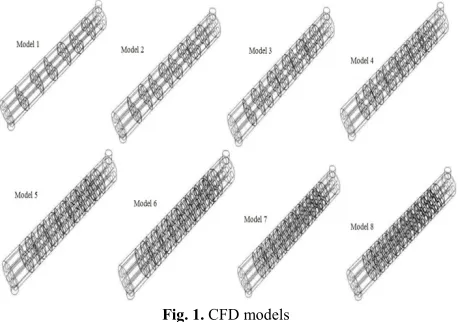
MATHEMATICAL MODELING DETAILS In this study, counter current flow shell and tube heat exchangers consisting of 7 tubes were considered. The heat exchangers were made out of Aluminum. The CFD models are shown in Figure1.
Fig. 1. CFD models
Fixed geometric parameters were similar to those in Ozden and Tari [29], as indicated in Table 1.
Table 1
Fixed geometric parameters [29].
The baffle spacing for eight CFD models is listed in Table 2.
Table 2
CFD models baffle spacing.
No. CFD models B(mm) Nb
1 86 6
2 61.43 8
3 47.78 10
4 39.09 12
5 33.07 14
6 28.67 16
7 25.30 18
8 22.63 20
The shell side and tube side fluids were γ-Al2O3-water nanofluids and pure water, respectively. In the current study, to define the properties of nanofluids, the single-phase method was used for nanofluids. It should be note that since the properties of γ-Al2O3-water nanofluids are
variable with temperature, they are defined by using UDF [30-32]. The properties of γ-Al2O3 nanoparticles used in the study were: density: ρp=3.97 g/cm3, thermal conductivity: Kp=40 W/mK, specific heat capacity: Cp=765 J/kg K. The following formulas were used to compute the thermo-physical properties of nanofluids in the UDF. The Einstein equation, which is suitable for small rigid spherical particles in the volume fraction of less than 5 vol.%, was used to estimate the viscosity of nanofluids [33]:
nf 1+2.5 bf
(1)
The density of nanofluids was calculated from equation 2 [34]:
nf p 1 bf
(2)
The effective thermal conductivity of nanofluids was given by the following equation [35]:
p bf p bf
nf bf
p bf p bf
k 2k 2 k k
k k
k 2k k k
(3)
The specific heat capacity can be calculated according to the following equation [35]:
p bf
P p
Pnf
nf
1 c c
c
(4)
Some simplifying assumptions were used to simulate the CFD models:
The fluid flow and heat transfer processes were turbulent.
The process was steady state.
The leak flows between tubes and the baffles and that between the baffles and the shell were neglected.
The heat exchanger was well insulated; hence the heat loss to the environment was totally neglected.
Single-phase method was used for nanofluids.
The γ-Al2O3 suspensions were Newtonian and incompressible fluids.
The governing equations for turbulent, steady state nanofluids flow can be written as follows [36].
Total continuity equation:
nfV
0 (5)
Equation of motion in three dimensions:
nf νV
P
nf V
(6)
BC L
Nt Tube bundle Geometry
and PT D0
Ds
25% 600mm 7
Triangular, 30 mm 20mm
32 Energy equation:
nfc V TP
knf T
(7)
In this study, the flow in the shell side was turbulent, so for the simulation of the CFD models, turbulence models had to be considered. Turbulence model used in this work was κ-ε model. This model has been used in different studies, proving to be suitable for turbulent flow simulation of nanofluids [37,38] and the shell and tube heat exchanger [29,39].
The second order upwind discretization scheme was selected for the equations of motion and energy and the first order upwind discretization scheme was employed for equations of turbulent kinetic energy and dissipation rate. To solve the governing equations, the convergence criteria residual for energy equation was 10-6 and that for other equations was 10-3.
The shell and tube volume was meshed using tetragonal-hybrid elements [29]. There were about 1,000,000 cells in each of CFD models.
The boundary conditions used are presented in Error! Reference source not found..To compute the shell side equivalent diameter for the triangular arrangement of tubes, the following formula was used [40].
2
e T
1.1
D P 0.917D
D o
s
(8)
The equivalent diameter in our CFD models is 29.326 mm.
Table 3
Boundary conditions.
Unit Tube (Cold) Shell (Hot)
Boundary condition Type
kg/s 0.5
0.5, 1, 2 Mass flow rate
Inlet
Pa 0
0 Pressure Outlet
Outlet
- Coupled No Heat Flux
No Slip Condition Wall
m 0.001 -
Wall Thickness
K 296 363
Inlet Temperature Temperature
RESULTS AND DISCUSSION
To validate the CFD models, the numerical results of pure water in the shell side for 6 baffles heat exchanger were compared with Kern and Bell-Delaware methods [40]. The overall heat transfer coefficients based on the shell side surface area and pressure drops in the shell side values, for our work and Kern and Bell-Delaware methods, are tabulated in Table 4. The overall heat transfer coefficients, as evaluated from CFD results, had an average deviation of 10.13%, 7.12% from that of Kern and Bell-Delaware methods, respectively. The pressure drop in shell side differences between our work and Kern method was increased with increasing the shell side mass flow rate. For pressure drop inside the shell, the maximum difference
between the CFD results and Bell-Delaware methods was 32.5%. It is observed that the CFD results are in good agreement with the Bell-Delaware results.
Table 4
Validation of CFD results. Nb Shell
side mass
flow rate kg s-1)
Working
fluid (W mU -2 K-1) P (kPa)
CFD
resultsmethod Kern Bell- Delaware method
CFD
results Kern methodDelawre Bell-method 6 0.5 water 1687 1666 1619 4.549 3.964 3.81
1 2463 2397 2263 9.100 7.598 8.42
2 3224 2548 2976 36.469 13.533 27.55
Figure 2 shows the heat transfer enhancement ratio, which is the ratio of nanofluids heat transfer rate to heat transfer rate of pure water, for different nanoparticles concentrations in various number of baffles. It was clear that the addition of nanoparticles to the base fluid increased the heat transfer rate.
Fig. 1. Heat transfer rate vs. number of baffles
Figure 3 represents the pressure drop inside the shell versus the nanoparticles volume concentration. As expected, the pressure drops was increased with increasing the baffles number. It seemed to show the insignificant effect of nanoparticles concentration on the pressure drop under turbulent flow conditions. For pure water, 1%, 1.5%, 2% and 2.5% of nanoparticles volume concentrations, the simulation results of heat exchangers models are shown in Table 5.
As expected, it was clear from the results that pressure drop and heat transfer rate were increased with baffles number. The results also showed that the addition of nanoparticles improved the thermal properties of the working fluids. The maximum heat transfer in the shell and tube heat exchanger occurred at 1 vol.%γ-Al2O3 nanofluid and higher concentrations of nanoparticles aggravated heat transfer rate. These results were similar to those reported in [41] for the experimental investigation of the steady state turbulent flow of γ-Al2O3-water nanofluid inside a circular tube.
Trans. Phenom. Nano Micro Scales, 4(1) 29-35, Winter - Spring 2016
33 nanofluids at higher than 1% nanoparticles volume concentrations.
The results also showed that pressure drop in the turbulent regime was slightly decreased with nanoparticles volume concentration as a function of baffle numbers.
Fig. 3. Pressure drop vs. numbers of baffles
Table 5
Boundary conditions.
Φ% Nb ΔP[kPa] Q,[kW] Φ% Nb ΔP[kPa] Q,[kW]
0 1
6 9.100 38.512 6 9.083 42.244 10 16.730 43.791 10 16.685 47.557 14 30.015 48.060 14 29.906 51.697 20 57.202 50.863 20 57.042 54.155
1.5 2
6 8.947 42.147 6 8.818 42.092 10 16.476 47.539 10 16.235 47.425 14 29.469 51.690 14 29.027 51.478 20 56.218 54.075 20 55.395 54.037
2.5
6 8.684 42.047
10 15.996 47.331
14 28.615 51.470
20 54.582 53.882
For the determination of the optimal baffle spacing, the effect of the number of baffles on pressure drop and heat transfer rate in the shell side for different nanoparticles volume concentrations was considered. It was evident that heat transfer rate and pressure drop were increased with number of baffles.
According to Table 5, for models with 14 or more baffles, the enhancement in heat transfer rate was reduced while pressure drop was strongly increased.
High pressure drop without a drastic change in the heat transfer rate was not desired. In other words, enhancement in heat transfer rate decreased for heat exchanger with 14 or more baffles.
This result is also shown in Figure 2 by trend curve. Therefore, model 4 had the best performance among the others and so, the optimal baffle spacing was 43.4% of the shell diameter.
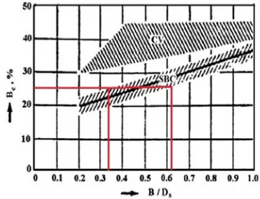
Due to the use of the single-phase model for nanofluids, the numerical results could be compared to those of Bell’s
method. The optimal range of baffles spacing from Bell’s method was between 33% and 61% of the shell diameter, as shown in Figure 4 [24].
Fig. 4.The suitable range of baffle spacing from Bell–Delaware method. SBC: segmental baffle cuts in no-phase-change flow; CV:
baffle cuts applicable to condensing vapors[24]
The suitable baffle spacing in this study obtained to be 43.4% of the shell diameter showing a good agreement with Bell’s method as shown in Figure 4.
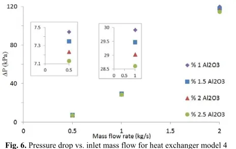
The effect of shell side mass flow rate on heat transfer and pressure drop was investigated in three different inlet mass flow rates of 0.5, 1 and 2 kg/s for model 4. The effects of mass flow rate on heat transfer rate and pressure drop in the shell side were shown in Figure 5 and Figure 6. respectively.
Fig. 5. Heat transfer rate vs. inlet mass flow rate for heat exchanger model 4
The results showed that pressure drop in shell side and heat transfer rate were increased with input mass flow rate. However, the enhancement in heat transfer rate was negligible compared to the pressure drop in the shell side. For 1 vol.% γ-Al2O3-water nanofluid, by increasing the input mass flow rate from 0.5 to 1 kg/s, the augmentation of heat transfer rate was about 36% while the pressure drop was 3 times bigger.
34 nanoparticles concentrations do not have a significant effect on pressure drop in the shell side.
Fig. 6. Pressure drop vs. inlet mass flow for heat exchanger model 4
CONCLUSION
The suitable baffle spacing in the CFD models of shell and tube heat exchangers was investigated under turbulent condition. Shell side fluid was γ-Al2O3-water with nanoparticles volume concentration of 0, 1, 1.5, 2 and 2.5%. By simulating heat exchangers with different baffles numbers and solving them in the same boundary conditions, the suitable baffle spacing was determined. The enhancement in heat transfer rate was reduced for the heat exchanger with 14 and more baffle numbers while the pressure drop was strongly increased. Therefore, the optimal baffle spacing was 43.4% of the shell diameter. The suitable baffle spacing in this study showed a good agreement with Bell-Delaware method.
The best thermal performance was for 1 vol.%γ-Al2O3 -water nanofluid and higher concentrations were not suitable for heat transfer enhancement. The results also showed that the pressure drop in turbulent flow regime was almost independent of nanoparticles concentration. The effect of inlet mass flow rate on the pressure drop in the shell side and heat transfer rate was investigated for the heat exchanger with 12 baffles. The shell side inlet flow rate was changed from 0.5 to 2 kg/s. The pressure drop shell side and heat transfer rate were increased with the mass flow rate. But the increase in heat transfer rate was less than that in pressure drop.
REFERENCES
[1] S. Kim, H. Chung, H. Jeong, B. Lee, B. Ochirkhuyag, J. Lee, H. Choi: The study of heat transfer for nanofluid with carbon nano particle in an exhaust gas recirculation (EGR) cooler, Heat and Mass Transfer 49 (2013) 1051-1055.
[2] R. Lotfi, A. M. Rashidi, A. Amrollahi: Experimental study on the heat transfer enhancement of MWNT-water nanofluid in a shell and tube heat exchanger, International Communications in Heat and Mass Transfer 39 (2012) 108-111.
[3] K. Y. Leong, R. Saidur, T. M. Mahlia, Y. H. Yau: Modeling of shell and tube heat recovery exchanger operated with nanofluid based coolants, International Journal of Heat and Mass Transfer 55 (2012) 808-816.
[4] L. Godson, K. Deepak, C. Enoch, B. Jefferson, B. Raja: Heat transfer characteristics of silver/water nanofluids in a shell and tube heat exchanger. Archives of Civil and Mechanical Engineering 14 (2014) 489-496.
[5] R. Aghayari, H. Maddah, F. Ashori, A. Hakiminejad, M. Aghili: Effect of nanoparticles on heat transfer in mini double-pipe heat exchangers in turbulent flow, Heat and Mass Transfer 51 (2014) 301-306.
[6] D. Madhesh, S. Kalaiselvam: Experimental study on the heat transfer and flow properties of Ag–ethylene glycol nanofluid as a coolant, Heat and Mass Transfer 50 (2014) 1597-1607.
[7] A. Hussein, R. A. Bakar, K. Kadirgama, K. V. Sharma: Heat transfer augmentation of a car radiator using nanofluids. Heat and Mass Transfer 50 (2014) 1553-1561.
[8] J. Cao, Y. Ding, C. Ma: Aqueous Al2O3 nanofluids: the important factors impacting convective heat transfer Heat and Mass Transfer 50 (2014) 1639-1648.
[9] Y. S. Son , J. Y. Shin: Performance of a shell-and-tube heat exchanger with spiral baffle plates, KSME International Journal 15 (2001) 1555-1562.
[10] B. K. Sonage, P. Mohanan: Heat transfer and pressure drop characteristic of zinc–water nanofluid, Heat and Mass Transfer 51 (2014) 521-527.
[11] C. Pang, J. W. Lee, Y. T. Kang: Review on combined heat and mass transfer characteristics in nanofluids, International Journal of Thermal Sciences 87 (2015) 49-67.
[12] D. Q. Kern: Process heat transfer, McGraw-Hill, New York (1950).
[13] R. W. Serth, T. G. Lestina: Process Heat Transfer, Second ed, Academic Press, Boston (2014).
[14] K. J. Bell: Delaware method for shell-side design, In: Kakaç S, Berger A, Mayinger F (eds) Heat exchangers: thermal-hydraulic fundamentals and design. Hemisphere (1981) 581-618.
[15] M. Kahani, S. Zeinali Heris, S. M. Mousavi: Experimental investigation of TiO2/water nanofluid laminar forced convective heat transfer through helical coiled tube, Heat and Mass Transfer 50 (2014) 1563-1573.
[16] X. Wang, A. S. Mujumdar: Heat transfer characteristics of nanofluids: a review, International Journal of Thermal Sciences 46 (2007) 1-19. [17] G. Huminic, A. Huminic: A: Heat transfer character-
Trans. Phenom. Nano Micro Scales, 4(1) 29-35, Winter - Spring 2016
35 [18] H. A. Mohammed, H. A. Hasan, M. A. Wahid: Heat
transfer enhancement of nanofluids in a double pipe heat exchanger with louvered strip inserts, International Communications in Heat and Mass Transfer 40 (2013) 36-46.
[19] B. H. Chun, H. U. Kang, S. H. Kim: Effect of alumina nanoparticles in the fluid on heat transfer in double-pipe heat exchanger system, Korean Journal of Chemical Engineering 25 (2008) 966-971.
[20] M. Akhtari, M. Haghshenasfard, M. R. Talaie: Numerical and Experimental Investigation of Heat Transfer of α-Al2O3/Water Nanofluid in Double Pipe and Shell and Tube Heat Exchangers, Numerical Heat Transfer, Part A: Applications 63 (2013) 941-958.
[21] B. Farajollahi, S. G. Etemad, M. Hojjat: Heat transfer of nanofluids in a shell and tube heat exchanger, International Journal of Heat and Mass Transfer 53 (2010) 12-17.
[22] M. M. Elias, I. M. Shahrul, I. M. Mahbubul, R. Saidur, N. A. Rahim: Effect of different nanoparticle shapes on shell and tube heat exchanger using different baffle angles and operated with nanofluid, International Journal of Heat and Mass Transfer 70 (2014) 289-297.
[23] A. Ghozatloo, A. Rashidi, M. Shariaty-Niassar: Convective heat transfer enhancement of graphene nanofluids in shell and tube heat exchanger, Experimental Thermal and Fluid Science 53 (2014) 136-141.
[24] J. Taborek: Thermal and hydraulic design of heat exchangers, In: Hewitt GF (ed) Handbook of Heat Exchanger Design 3 (2002).
[25] R. Mukherjee: Use double-segmental baffles in the shell-and-tube heat exchangers, Chem Eng Progress 88 (1992) 47–52.
[26] M. Saffar-Avval, E. Damangir: A general correlation for determining optimum baffle spacing for all types of shell and tube exchangers, International Journal of Heat and Mass Transfer 38 (1995) 2501-2506.
[27] B. Khalifeh Soltan, M. Saffar-Avval, E. Damangir: Minimizing capital and operating costs of shell and tube condensers using optimum baffle spacing, Applied Thermal Engineering 24 (2004) 2801-2810. [28] D. Eryener: Thermoeconomic optimization of baffle spacing for shell and tube heat exchangers, Energy Conversion and Management 47(2006) 1478-1489. [29] E. Ozden, I. Tari: Shell side CFD analysis of a small
shell-and-tube heat exchanger, Energy Conversion and Management 51 (2010) 1004-1014.
[30] R. Mukherjee: Use double-segmental baffles in the shell-and-tube heat exchanger, chem Eng progress88 (1992) 47–52.
[31] A. Sasmito, J. Kurnia, A. Mujumdar: Numerical evaluation of laminar heat transfer enhancement in nanofluid flow in coiled square tubes, Nanoscale Research Letters 6 (2011) 1-14.
[32] A. K. Tiwari, P. Ghosh, J. Sarkar, H. Dahiya, J. Parekh: Numerical investigation of heat transfer and fluid flow in plate heat exchanger using nanofluids, International Journal of Thermal Sciences 85 (2014) 93-103.
[33] Y. Xuan, W. Roetzel: Conceptions for heat transfer correlation of nanofluids, International Journal of Heat and Mass Transfer 43 (2000) 3701-3707. [34] B. C. Pak, Y. I. Cho: Hydrodynamic and heat
transfer study of dispersed fluids with submicron metallic oxide particles, Experimental Heat Transfer 11 (1998) 151-170.
[35] A. A. Minea: Uncertainties in modeling thermal conductivity of laminar forced convection heat transfer with water alumina nanofluids, International Journal of Heat and Mass Transfer 68 (2014) 78-84. [36] M. Keshavarz Moraveji, M. Hejazian: Modeling of
turbulent forced convective heat transfer and friction factor in a tube for Fe3O4 magnetic nanofluid with computational fluid dynamics, International Communications in Heat and Mass Transfer 39 (2012) 1293-1296.
[37] A. Kamyar, R. Saidur, M. Hasanuzzaman: Application of Computational Fluid Dynamics (CFD) for nanofluids, International Journal of Heat and Mass Transfer 55 (2012) 4104-4115.
[38] O. Kaya: Numerical study of turbulent flow and heat transfer of Al2O3–water mixture in a square duct with uniform heat flux, Heat and Mass Transfer 49 (2013) 1549-1563.
[39] R. R. T. Karuppa, G. Srikanth: Shell side numerical analysis of a shell and tube heat exchanger considering the effects of baffle inclination angle on fluid flow using CFD, Thermal Science 16 (2012) 1165-1174.
[40] G. Towler, R. Sinnott: Chemical engineering design: principles, practice and economics of plant and process design. Butterworth-Heinemann (2008). [41] B. Sahin, G. G. Gültekin, E. Manay, S. Karagoz: