0 INTRODUCTION
Since its introduction into human neurosurgery by Spiegel and Wycis almost 70 years ago, the stereotactic frame has been used as a standard targeting method for functional intracranial procedures, biopsies, and
deep brain stimulation [1]. With advances in
image-guided neurosurgical procedures over the past 30 years, alternative methods of performing surgical interventions have become more widely used by neurosurgeons [2] to [5]. The first application of a robot in medicine was in the field of neurosurgery when an industrial robot, PUMA 200, was successfully used in a frame-based configuration for a brain biopsy
procedure in 1985 [6]. There are a few reasons that
the first application of robotic technology was in the field of neurosurgery. As noted in [7], the human brain is an organ which is uniquely suited for robotic applications. It is symmetrically confined within a rigid container (the skull), which offers the potential of accurate patient localization by a robotic or external localization system.
One of the greatest obstacles to the widespread robotization of neurosurgical procedures is the total
cost of robotic systems, which remain very high [8].
One example is the Neuromate stereotactic robot (Renishaw, Gloucestershire, UK) [9]. The R&D costs are estimated at over 30 million US dollars [10]; this fact contributes to the higher price of this system. Another example is the Renaissance system (Mazor Robotics Ltd., Caesarea, Israel) which has a total
system cost of 789,000 US dollars [11]. This cost
includes the robot, an instrument tray, a dedicated workstation and a year of free technical support. Therefore, it is necessary for hospitals to ensure that the benefits brought by robotic surgery outweigh the costs.
In contrast, standard industrial robots come in a wide range of kinematic configurations (serial-link manipulators with six or seven revolute joints) and robot reach specifications that make them suitable for a wide variety of applications in neurosurgery.
Table 1 gives an overview of standard industrial robots that have been implemented as part of commercial or research neuronavigation robotic systems since the year 2000. One benefit of implementing industrial robots is that the research and development of the robotic arm have been done by the robot manufacturer, contributing to a lower overall system price. Regarding strict medical regulations and
A Novel Robotic Neuronavigation System: RONNA G3
Švaco, M. – Šekoranja, B. – Šuligoj, F. – Vidaković, J. – Jerbić, B. – Chudy, D.
Marko Švaco1,2,* – Bojan Šekoranja1,2 – Filip Šuligoj1,2 – Josip Vidaković1,2 – Bojan Jerbić1,2 – Darko Chudy3,4 1 University of Zagreb, Faculty of Mechanical Engineering and Naval Architecture, Croatia
2 University Hospital Dubrava, Associate at the Department of Neurosurgery, Croatia 3 University Hospital Dubrava, Department of Neurosurgery, Croatia
4 University of Zagreb, School of Medicine, Croatian Institute for Brain Research, Croatia
This paper presents a novel robotic neuronavigation system, RONNA G3, developed for frameless stereotactic navigation based on standard industrial robots. The basic version of the RONNA G3 system has three main components: a robotic arm on a universal mobile platform, a planning system, and a navigation system. We have developed a stereovision localization device (RONNAstereo) that can be attached to the robot end effector for accurate non-contact localization of the patient in the operating room. RONNAstereo has two infrared (IR) cameras with macro lenses aligned at a 55° angle in the same plane. We have evaluated the application accuracy of the RONNA G3 system in a phantom study with two different registration methods. The first registration method involves a rigid fiducial marker with four retroreflective spheres (spherical fiducials). The second method uses freely distributed individual spherical fiducials mounted on single bone screws. We have evaluated the RONNA G3 positioning error for superficial (< 50 mm) and deep (50 mm to 120 mm) targets. The mean target positioning error (TPE) of the RONNA G3 system for superficial and deep targets was 0.43 mm (interquartile range 0.22 mm to 0.60 mm) and 0.88 mm (interquartile range 0.66 mm to 1.10 mm), respectively. Given the positioning errors from the phantom trials, we have prepared the system for clinical trials, which are currently in progress.
Keywords: robotic neuronavigation, frameless stereotaxy, minimally invasive surgery, RONNA G3
Highlights
• An overview of standard industrial robots used for neuronavigation.
• A novel dual-arm robotic neuronavigation system, RONNA G3, based on standard industrial robots.
standards, which are indicated in [12], one alternative to standard industrial robots is robot manipulators certified as medical devices. An example of that alternative is the newly developed Kuka LBR Med medical lightweight robot (KUKA, Augsburg, Germany). As presented by the KUKA Healthcare robotics division [13], the LBR Med lightweight robot will be tested in accordance with IEC 60601-1, the technical standards for the safety and effectiveness of medical electrical equipment. The robot will be distributed with a CE label for EMC (IEC 60601-1-2:2014), which will ensure an even easier integration into medical devices. Despite this fact, standard industrial robots that are incorporated in the AQRATE
system (KB Medical SA, Lausanne, Switzerland) [14],
the ROSA Spine (Medtech, Montpellier, France) [15],
and the ROSA Brain (Medtech) [16] have obtained
both the CE mark and the FDA approval. This fact confirms the medical applicability of standard industrial robots as part of medical devices (details are given in Table 1).
Since 2015, four innovative robotic neuronavigation systems have been developed based on standard industrial robots from KUKA [14], Stäubli
[15] and Universal robots [18] to [20] (details are given in Table 1). These systems are not included in the current state-of-the-art literature survey and review papers [29] to [32]; this demonstrates the very rapid development of the field of robotized neuronavigation medical.
The development of a novel robotic neuronavigation system, RONNA G3, based on standard industrial robots. We have validated the
RONNA G3 system in an in vitro phantom trial which showed application accuracies suitable for the application in human clinical trials. At the end of the paper, we present a workflow for robotized stereotactic brain biopsy procedures that are currently being conducted as part of the clinical trials with the RONNA G3 system at the Department of Neurosurgery, University Hospital Dubrava, Croatia. We have received the approval of the Ethical Committee of the University Hospital Dubrava and the School of Medicine, University of Zagreb, and we have been given consent from each patient included in the clinical trials.
1 THE RONNA G3 SYSTEM
We have extensively upgraded the previously
developed RONNA system [23]. That system was
tested through rigorous preclinical trials which resulted in numerous improvements and in the development of the new RONNA G3 system.
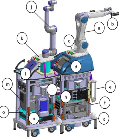
RONNA G3 (Figs. 1 and 2) is designed and used for stereotactic neuronavigation procedures. The RONNA G3 system consists of a robotic arm mounted on a specially designed universal mobile platform, a global Optical Tracking System (OTS), and planning software. A localization feature (rigid fiducial marker or freely distributed bone mounted fiducials, shown in Fig. 3) is used for the patient registration, while a stereovision system (RONNAstereo) is used for the patient localization in the physical space. The robots are equipped with surgical tools (guides, grippers, drill, etc.). A specific characteristic of the RONNA
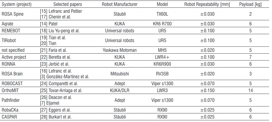
Table 1. Overview of industrial robots used for neuronavigation since the year 2000
System (project) Selected papers Robot Manufacturer Model Robot Repeatability [mm] Payload [kg]
ROSA Spine [15] Lefranc and Peltier [17] Chenin et at. Stäubli TX60L ±0.030 2
Aqrate [14] Patel KUKA KR6 R700 ±0.030 6
REMEBOT [18] Liu Yu-peng et al. Universal robots UR5 ±0.100 5
TIRobot [19] Tian et al.[20] Tian Universal robots UR5 ±0.100 5
not specified [21] Faria et al. Yaskawa Motoman MH5 ±0.020 5
Active project [22] Beretta et al. KUKA LWR4+ ±0.100 7
RONNA [23] Jerbić et al. KUKA KR6R900 ±0.030 6
ROSA Brain [16] Lefranc et al. [3] González-Martínez et al. Mitsubishi RV3SB ±0.020 3
ROBOCAST [24] Comparetti et al. Adept Viper s1300 ±0.070 5
OrthoMIT [25] Tovar-Arriaga et al. KUKA/DLR LWR3 ±0.150 14
Pathfinder [26] Deacon et al.
[7] Eljamel Adept Viper s1300 ±0.070 5
RobaCKa [27] Eggers et al. Stäubli RX90 ±0.025 6
G3 system with respect to the most current state-of-the art robotic neurosurgical systems [29] to [32] is an additional mobile platform equipped with a compliant and sensitive robotic arm which makes it a dual-arm robot system (master and assistant robots). The robots are standard six degree-of-freedom (DOF) revolute robots. This enables full flexibility and reorientations around operative trajectories defined with five parameters (three translations and two rotations).
The system design and functional requirements in neurosurgical robotics are much more demanding than in conventional robotics, e.g. in industrial applications. First, the robotic system must be compact enough to fit in the Operating Room (OR) and should not interfere with the procedure of medical staff. On the other hand, the robotic system must meet complex requirements in terms of spatial working ability. Therefore, the robot system setup was designed using CAD software
which enabled modelling and simulations [33] and
[34]. Various trajectories and surgical instruments
involved in neurosurgery were explored, as well as the requirements to be met regarding the location of the whole system in the operating room in relation to other equipment and medical staff.
Fig. 1. The main components of the RONNA G3 robot platforms:
(a) Master robot – Kuka KR6 R900, (b) RONNAstereo, (c) Control
panel, (d) Master robot teach pendant, (e) mechanical link for the operating table, (f) Master robot controller, (g) hydraulic lifting system, (h) UPS (Uninterruptible Power Supply), (i) cooling system,
(j) Assistant robot – Universal robotics UR5, (k) Control panel,
(l) Assistant robot teach pendant, (m) Assistant robot controller, (n) High-speed medical drill control system, (o) UPS
Since the RONNA G3 provides a dual-arm configuration, a special algorithm is applied to control the movement of two robots. The control algorithm is used to calculate optimal joint configurations of both robots in mutual target operation points by assuring the high dexterity of each robot and preventing collision between them. The algorithm calculates the robot configurations in the joint space based on a multi-objective cost function (Q) composed of three criteria: the condition number (c), Joint Limit
Avoidance (JLA), and collision avoiding criteria (d) based on utilizing the roll angle of the trajectory:
min , , .
robot configurations joint space∈ Q c JLA d
(
)
(1)Parameters c and JLA are concerned with the
dexterity of the robots, while d assures the collision-free cooperation of robots. Robot configurations are input vectors containing angular displacements of joints for both robots. These input vectors are obtained by searching the entire range of possible joint states of the robots (joint space). Each operational target point requires the computation of optimal joint configurations based on Eq. (1).
RONNA G3 is designed to work in a single robot mode or in a dual-arm mode, depending on the type of surgery and the surgeon’s choice. In both cases, the patient should be under anaesthesia with the head fixed in a head holder (Mayfield clamp). The master robot is used for accurate routing of surgical instruments (drill, needle, or any other instrument) to the planned position and in the desired orientation. Insertion of the instrument in the direction of the operation point can be done by the assistant robot or by the neurosurgeon. When the operation is performed only with the master robot, the robot is used only as a navigation instrument (guide).
The extended version of RONNA G3 which uses both robotic arms is intended for automated robotic bone drilling applications and manipulation of surgical instruments. The assistant robot inserts the operating instrument into the tool guide pointing toward the operation point. In addition, the assistant robot is intended for assisting the surgeon through intuitive human-robot collaboration [35].
For the global navigation in the OR, the OTS uses an infrared stereo camera (Polaris Spectra, NDI - Northern Digital Inc., Ontario, Canada) and two reference frames, one attached to the patient and the other to the robotic arm. The OTS is only used for coarse positioning of the robot with respect to the patient in the global localization phase of the
the main accuracy categories of the robot system guided with an OTS. When using relative referencing and two reference frames (markers), the root-mean-square positioning error of the OTS was 0.398 mm and showed a strong growth tendency with larger distances between the two markers. We have developed a localization device (RONNAstereo) which eliminates any errors that may arise from the low resolution and a wide field of view of the global
OTS [36]. The RONNAstereo is described in Section
1.1.2.
Fig. 2. The RONNA G3 system (render): (A) master robot, (B)
assistant robot, (C) universal mobile platform, (D) optical tracking
system, (E) control and planning software interface
1.1 Patient Registration
Patient registration implies determining a spatial transformation between coordinate systems of the medical diagnostic images (CT scan) and the patient. In the patient registration process, the RONNA G3 can use two different marker types: a rigid fiducial marker with four standard medical retroreflective spheres (spherical fiducials) shown in Fig. 3a or freely distributed individual spherical fiducials mounted on individual bone screws (Figs. 3b and c).
Fig. 3. RONNA registration methods: a) rigid fiducial marker, b) two freely distributed bone screws, and c) a bone screw with the
spherical fiducial mounted on its top
In both cases, individual spherical fiducials need to be localized in the image space and the physical space with a minimum of three spherical fiducials that are positioned at the same distance from each other.
Fig. 4. RONNA planning software (RONNAplan) – the target point (orange sphere) is shown in the: b) axial plane, c) sagittal plane, and d)
The transformation is defined by a 3×3 rotation matrix and a 3D position vector that describe the position and the orientation of the image space coordinate system with respect to the physical space coordinate system. RONNAstereo is used for patient localization in the physical space, while either the developed automatic localization algorithm or manual localization is used for the localization of spherical fiducials in the image space.
The RONNA G3 system incorporates software for operation planning (RONNAplan) based on computed tomography (CT) or magnetic resonance imaging (MRI). RONNAplan and its features are developed for satisfying the needs of neurosurgical applications based on the open source medical visualization software Medinria (Inria, France). This software allows the definition of trajectories through a visual, image-based user interface that enables the selection of entry and target points. Two- and three-dimensional visualization of the planned trajectories, as well as the editing and storing of the surgical plan, are supported by this software. The generated surgical plan can be automatically transferred to the robot control software after the planning phase has been completed. An example of a surgical plan is shown in Fig. 4.
1.1.1 Image Space Localization
In the RONNA G3 surgery procedure, image space localization is conducted after the patient with the attached fiducial marker has been subjected to a CT scan. If the localization is done manually, the operator visually determines the centre of every spherical fiducial using the RONNAplan software. Manual localization has drawbacks, such as insufficient localization accuracy, long duration, and the possibility of human error. To overcome these drawbacks, we have developed an automated algorithm for the accurate localization of spherical fiducials in the image space. This localization algorithm uses a combination of machine vision algorithms, biomedical image filtration methods, and mathematical estimation methods. A pre-processing step of the localization algorithm is the intensity-based filtration of voxels. The filter isolates the space around high Hounsfield values of the titanium pins used for mounting the spherical fiducials. Since the cross-section of a spherical fiducial is a circle, an algorithm based on the circle Hough transform
[37] is used for finding all the potential circles in the filtered axial and sagittal image projections. Spheres are verified, and false positive detections are removed with Euclidean distance filters. Finally, to calculate
the spherical fiducial centre from the detected circles, we implemented an algorithm that matches a set of points to algebraic surfaces using the direct least square method. Based on the measurements conducted in clinical conditions on patients and on various test phantoms, the localization algorithm has shown a higher accuracy and speed in comparison with the manual localization carried out by human operators. The algorithm showed 100 per cent reliability with successful localizations of the fiducial marker in twenty test cases.
1.1.2 Physical Space Localization
Physical space localization is automated with an OTS. The OTS can detect spherical fiducials located on the robotic arm and the patient simultaneously, as shown in Fig. 5. When a relative spatial relation between the robot coordinate system and the patient coordinate system is established, the robot uses the stereovision localization device (RONNAstereo) for accurate localization. RONNAstereo consists of two infrared cameras (acA2000-50gmNIR, Basler, Ahrensburg, Germany) with macro lenses aligned at a 55° angle in the same plane. The RONNAstereo was considerably improved with respect to its initial version presented in [23]. By determining the position of a corresponding point in both images, a virtual tool centre point (TCP) is defined. The virtual TCP is calibrated so that it corresponds with the TCP of a calibrated surgical tool. The robot TCP coordinate system is aligned within 0.05 mm using the RONNAstereo TCP and the physical tip of the surgical tool. The stereovision images are processed using machine vision software running the least-squares circular edge fit algorithm
[37] and contrast enchantment [38] that actively
determine the position of a localized spherical fiducial with respect to the robot’s TCP. The system allows the positioning of the robot’s TCP within 0.03 mm off a detected spherical fiducial centre. To the best of our knowledge, the developed localization device (RONNAstereo), which is held by our robot during the patient localization, is a novelty in the field of robotic neuronavigation systems and their noncontact frameless localization techniques. The ROSA robot
[16] (Medtech, Montpellier, France) in the frameless
mode uses a laser measurement device for surface scanning of the patient, while the Neuromate robot [39]
(Renishaw, Gloucestershire, UK) uses an ultrasound localizer (transmitter and receiver). The Pathfinder
robot [40] (Prosurgics Ltd., High Wycombe, UK) used
Fig. 5. Physical space patient localization
2 EXPERIMENTAL SETUP – PHANTOM TRIALS
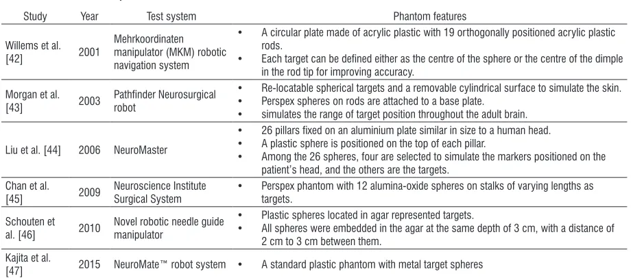
In the in vitro accuracy evaluation, the positioning accuracy of RONNA G3 was measured on a test phantom (Fig. 6.). The test phantom consists of a polymer base with one central pillar, 16 randomly distributed spherical fiducials, and a rigid fiducial marker. The centre of each spherical fiducial can be used as a target point. Accuracy measurements based on phantoms with spherical targets are commonly used to assess in vitro positioning accuracy of robotic neurosurgical systems. An overview of phantom designs used for the testing of various robotic neuronavigation systems is given in Table 2. In our
previous research, we evaluated a number of different phantom target designs [41].
Fig. 6. The test phantom; a) a rigid fiducial marker attached to the phantom, b) three randomly distributed spherical fiducials mounted via individual bone screws, which define the phantom
coordinate frame
We obtained three CT scans (Somatom Emotion®,
Siemens, Erlangen, Germany) of our phantom. Each scan contained a different number of slices: CT1 - 283 slices, CT2 - 357 slices, and CT3 - 358 slices. Each scanning orientation was completely different in respect to the scanning plane. We used our standard head protocol: gantry rotation time 0.6 s, helical scanning, detector collimation 16 mm × 0.6 mm, slice width 0.75 mm, reconstruction increment 0.7 mm, image matrix 512 × 512 with a voxel size of 0.5 mm × 0.5 mm × 0.7 mm, no gantry.
We evaluated both registration methods by registering each CT scan from the image space in the physical space. In the first case, we used the rigid fiducial marker attached to the phantom (Fig. 6a) to define the phantom coordinate frame. In the second
Table 2. Phantom accuracy studies
Study Year Test system Phantom features
Willems et al.
[42] 2001
Mehrkoordinaten manipulator (MKM) robotic navigation system
• A circular plate made of acrylic plastic with 19 orthogonally positioned acrylic plastic rods.
• Each target can be defined either as the centre of the sphere or the centre of the dimple in the rod tip for improving accuracy.
Morgan et al.
[43] 2003 Pathfinder Neurosurgical robot
• Re-locatable spherical targets and a removable cylindrical surface to simulate the skin. • Perspex spheres on rods are attached to a base plate.
• simulates the range of target position throughout the adult brain.
Liu et al. [44] 2006 NeuroMaster
• 26 pillars fixed on an aluminium plate similar in size to a human head. • A plastic sphere is positioned on the top of each pillar.
• Among the 26 spheres, four are selected to simulate the markers positioned on the patient’s head, and the others are the targets.
Chan et al.
[45] 2009 Neuroscience Institute Surgical System • Perspex phantom with 12 alumina-oxide spheres on stalks of varying lengths as targets.
Schouten et al. [46] 2010
Novel robotic needle guide manipulator
• Plastic spheres located in agar represented targets.
• All spheres were embedded in the agar at the same depth of 3 cm, with a distance of 2 cm to 3 cm between them.
Kajita et al.
case, we used three randomly distributed spherical fiducials mounted via individual bone screws (Fig. 6b) to define the phantom coordinate frame. In clinical practice, the second method allows for a variation in the marker size and allows for the coordinate registration system to be closer to the target points.
Target positions in the image space of the spherical fiducials are obtained using the sphere extraction algorithm presented in the patient registration section in all three CT scans. The localized spherical fiducial centres and one planned trajectory are shown in Fig. 7 within the RONNAplan interface.
Fig. 7. RONNA planning software (RONNAplan); green spheres depict automatically localized spherical fiducials of the rigid marker; the planned trajectory is shown in yellow; the entry point is
shown in blue, and the target position is shown in orange
For accurate measurement, the robot used RONNAstereo to position its virtual TCP within 0.03 mm off each spherical fiducial centre. As shown in Fig. 6, three spherical fiducials were used for determining the phantom coordinate system in the image space and the physical space. After the phantom is localized, the virtual TCP of the robot is positioned at the calculated coordinates of the spherical targets denoted as pi. The robot’s position is corrected afterward to the exact centre pc of each spherical fiducial with the previously described circular edge detection algorithm. The robot positioning error is calculated as the Euclidian
distance between the initial position pi and the
corrected position pc, of the virtual TCP of the robot. error= (x xi− c) +(y yi− c) +(z zi− c) ,
2 2 2
(2)
where xc, yc and zc are the corrected position
coordinates in the x, y and z direction in the
RONNAstereo coordinate frame.
We obtained target positioning errors (TPE) for 10 random phantom positions and orientations in the robot workspace. We repeated the measurement for each of the three CT scans. To obtain valid TPE data, the spherical fiducials that form the localization coordinate system were left out in both cases because they do not contain the full CT localization error. Also, three unreachable (not visible) target points were neglected. Finally, the experiment yielded 10 usable target points. In total, 300 position measurements were conducted.
Fig. 8. Positioning error for superficial (1) and deep targets (2)
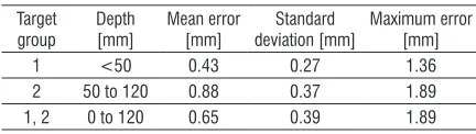
Table 3. Accuracy of the RONNA system Target
group
Depth [mm]
Mean error [mm]
Standard deviation [mm]
Maximum error [mm]
1 <50 0.43 0.27 1.36
2 50 to 120 0.88 0.37 1.89
1, 2 0 to 120 0.65 0.39 1.89
Furthermore, kinematic calibration of the
robot was performed to determine its TCP [48].
It is carried out by targeting a point in the robot workspace in multiple different orientations. Using the joint configurations from the same spatial point, an optimization of the TCP coordinates is performed by minimizing the residuals of the end effector poses,
as shown in [49]. Other kinematic parameters of the
robot are not altered.
spherical fiducials. Significant differences between the superficial and the deep targets regarding the positioning accuracy can be observed both in the values of the mean (0.43 mm and 0.88 mm) and maximum errors (1.36 mm and 1.89 mm). Accuracies with errors of less than 0.5 mm, which satisfy the stereotactic procedure requirements, can be achieved if the target points are close to the marker coordinate system (<50 mm), i.e. with superficial target points.
It should be noted that the conducted phantom trial does not consider several factors influencing the overall accuracy occurring in in vivo applications
[50]. These factors include inaccuracies of the surgical instruments (e.g. a slight curvature of the biopsy needle), the brain shifting during bone drilling, and other surgery-related specific effects. Furthermore, the phantom trial underestimates errors that can arise from the patient movement, the patient-dependent distortion of the image and the difficulties in identifying the position of the biological target rather than the fiducial target [39]. Thus, it can be expected that the absolute accuracy in future clinical trials will be degraded due to the above listed factors. This has already been confirmed by recent clinical case studies with the Neuromate [2] and ROSA [3], [16] robotic systems.
3 SURGICAL WORKFLOW ASSISTED WITH THE RONNA G3 SYSTEM
The RONNA G3 clinical procedure is divided into three phases: preoperative phase (I), preparation phase (II), and operation phase (III).
In the preoperative phase (I), either the bone attached marker or distributed bone screws are fixed to the patient’s head under local anaesthesia. The day before the surgery, the patient is subjected to a CT scan. After that, the marker is removed from the bone screw to reduce the patient’s discomfort. In the next step, the surgeon imports the medical diagnostic images into the RONNAplan software. The surgeon plans and defines all necessary operation points and trajectories (defined with accompanying entry points) while the spherical fiducials are localized automatically.
In the preparation phase (II), the patient is brought to the OR. The patient is given general anaesthesia, and his head is fixed in a head holder (Mayfield clamp). The marker is reattached to the bone screw, or the freely distributed individual spherical fiducials are attached to single bone screws. To obtain the initial patient position in the OR, the robot platform position is adjusted to the patient according to the planning
module algorithm (1) and the position is verified with the OTS. The robot platform is then fixed to the operating table to ensure stability and rigidity of the entire setup. The system proceeds to the accurate marker localization using RONNAstereo, as described in section 1.1.2. After localization and registration, RONNAstereo is removed from the robot end effector and replaced with a tool guide. The surgeon then verifies the localization procedure using the tool guide to point at anatomical landmarks on the patient’s head. In the operation phase (III), the operating field is washed by alcohol and a sterile cover is put on the patient and on the robot. A sterile set of end effector tools is used. Using RONNAplan, the surgeon selects the preoperatively planned trajectory and the robot positions the tool guide accordingly. In this phase of clinical trials, the system is used for brain tissue biopsies. The robot is equipped with a sterile tool holder for a twist drill (3.2 mm in diameter) and a biopsy needle (2.5 mm in diameter). Skin incision and drilling of the burr hole are performed by the neurosurgeon. After the dura has been opened and coagulation has been performed, a 2.5 mm diameter biopsy needle is advanced to the target and staged biopsy is performed. When the surgeon completes the biopsy at the target point, the robot can retract to its home position or reposition at another target.
4 CONCLUSIONS
There are numerous advantages of the application of robotic technology in neurosurgery. Endurance is the first benefit of robotics given that several studies have demonstrated that surgeons suffer from muscle fatigue during operations as a result of the procedure duration and the need to hold surgical instruments at specific
angles [40]. By using a robotic arm to steady the
surgical instrument, the problems of fatigue and tremor can be eliminated. Robots are also able to extend the visual and manual dexterity of neurosurgeons beyond
their limits as pointed out by Eljamel [7] because
they can work through very narrow and long surgical corridors most suited for brain surgery. Apart from the frameless approach, neurosurgical robotic systems can provide a number of advantages for the surgical procedure, such as the elimination of tremor, lower risk of error due to the surgeon’s fatigue and faster completion of the operation.
techniques are the ease of use, less patient discomfort, and more flexible pre-operative planning with the ability to separate the imaging from the surgical procedure, which provides ample time for a detailed image analysis and trajectory planning [39] and [51]. We have evaluated the application accuracy of the RONNA G3 system in a phantom study with two different registration methods. The first registration method involves a rigid fiducial marker with four spherical fiducials. The second method uses randomly distributed spherical fiducials mounted on individual bone screws. The mean positioning error for superficial targets (< 50 mm) was 0.43 mm (interquartile range 0.22 mm to 0.60 mm) and for deep targets (50 mm to 120 mm), it was 0.88 mm (interquartile range 0.66 mm to 1.10 mm). Given the positioning errors obtained from the phantom trials, we have prepared the system for clinical trials which are currently in progress. The RONNA G3 system has two key features that differentiate it from current robotic neuronavigation systems used for neurosurgical interventions. The first key feature of our system is a specially designed universal mobile platform that can be used for different robot types. The second feature is a new high precision non-contact localization system, RONNAstereo. Furthermore, RONNA G3 utilizes a novel automatic localizing
algorithm [52] developed for improved preoperative
spherical fiducial localization.
In future work, we plan to evaluate the clinical application accuracy of the RONNA G3 system for frameless stereotactic brain biopsy procedures. In the prospective clinical study using the RONNA G3 system, in addition to reporting the target point error and accuracy measurements, we plan to report other measuring metrics; these will include diagnostic yield, operating time, and intraoperative and postoperative complications. In addition, we are working on the development and testing of bone drilling procedures on animal bone specimens using a second robot, as well as on task planning algorithms for increasing the robot autonomy [53] and [54].
5 ACKNOWLEDGEMENTS
The authors would like to acknowledge the support of the Croatian Scientific Foundation through the research project ACRON - A new concept of Applied Cognitive RObotics in clinical Neuroscience. The authors would like to thank Domagoj Dlaka, Fadi
Almahariq, and Dominik Romić from the University
Hospital Dubrava for their support in the development and evaluation phases of the RONNA G3 system.
6 REFERENCES
[1] Henderson, J.M., Holloway, K.L., Gaede, S. E., Rosenow, J.M. (2004). The Application accuracy of a skull-mounted trajectory guide system for image-guided functional neurosurgery. Computer Aided Surgery, vol. 9, no. 4, p. 155-160,
DOI:10.3109/10929080500050249.
[2] Cardinale, F., Cossu, M., Castana, L., Casaceli, G., Schiariti, M.P., Miserocchi, A., Fuschillo, D., Moscato, A., Caborni, C., Arnulfo, G., Lo Russo, G. (2013). Stereoelectroencephalography: surgical methodology, safety, and stereotactic application accuracy in 500 procedures. Neurosurgery, vol. 72, no. 3, p. 353-366, DOI:10.1227/NEU.0b013e31827d1161.
[3] González-Martínez, J., Bulacio, J., Thompson, S., Gale, J., Smithason, S., Najm, I., Bingaman, W. (2016). Technique, Results, and complications related to robot-assisted
stereoelectroencephalography. Neurosurgery, vol. 78, no. 2, p.
169-180, DOI:10.1227/NEU.0000000000001034.
[4] Minchev, G., Kronreif, G., Martínez-Moreno, M., Dorfer, C., Micko, A., Mert, A., Kiesel, B., Widhalm, G., Knosp, E., Wolfsberger, S. (2017). A novel miniature robotic guidance device for stereotactic neurosurgical interventions: preliminary experience with the iSYS1 robot. Journal of Neurosurgery, vol.
126, no. 3, p. 985-996, DOI:10.3171/2016.1.JNS152005.
[5] Lefranc, M., Le Gars, D. (2012). Robotic implantation of deep brain stimulation leads, assisted by intra-operative, flat-panel CT. Acta Neurochirurgica, vol. 154, no. 11, p. 2069-2074,
DOI:10.1007/s00701-012-1445-7.
[6] Kwoh, Y.S., Hou, J., Jonckheere, E.A., Hayati, S.(1988). A Robot with improved absolute positioning accuracy for CT guided
stereotactic brain surgery. IEEE Transactions on Biomedical Engineering, vol. 35, no. 2, p. 153-160, DOI:10.1109/10.1354.
[7] Eljamel, M.S. (2007). Validation of the PathFinderTM neurosurgical robot using a phantom. The International
Journal of Medical Robotics and Computer Assisted Surgery,
vol. 3, no. 4, p. 372-377, DOI:10.1002/rcs.153.
[8] Bertelsen, A., Melo, J., Sánchez, E., Borro, D. (2013). A review of surgical robots for spinal interventions. The International Journal of Medical Robotics and Computer Assisted Surgery,
vol. 9, no. 4, p. 407-422, DOI:10.1002/rcs.1469.
[9] von Langsdorff, D., Paquis, P., Fontaine, D. (2015). In vivo measurement of the frame-based application accuracy of the Neuromate neurosurgical robot. Journal of Neurosurgery, vol.
122, no. 1, p. 191-194, DOI:10.3171/2014.9.JNS14256.
[10] Neuromate Key Features (2016). Datasheet H-4149-0031-01,
Reinshaw, Gloucestershire.
[11] Joskowicz, L., Shamir, R., Israel, Z., Shoshan, Y., Shoham, M. (2011). Renaissance robotic system for keyhole cranial neurosurgery: in-vitro accuracy study. Proceedings of the
Mexican Symposium on Computation and Robotics in
Medicine.
[12] Haidegger, T., Rudas, I.J. (2015). From concept to market: surgical robot development. Handbook of Research on Advancements in Robotics and Mechatronics, IGI Global, Hershey, DOI:10.4018/978-1-4666-7387-8.ch010.
[13] Cyrill von Tiesenhausen. (2016). KUKA LBR Med Overview,
[14] Spine Health Institute (2016). Dr. Patel Performs Groundbreaking Robotic Surgery in Switzerland, from: http:// www.thespinehealthinstitute.com/news-room/health-blog- news/dr-patel-performs-groundbreaking-robotic-surgery-in-switzerland, accessed on 2017-06-03.
[15] Lefranc, M., Peltier, J. (2016). Evaluation of the ROSATM spine robot for minimally invasive surgical procedures. Expert
Review of Medical Devices, vol. 13, no. 10, p. 899-906,
DOI:10.1080/17434440.2016.1236680.
[16] Lefranc, M., Capel, C., Pruvot, A. S., Fichten, A., Desenclos, C., Toussaint, P., Le Gars, D., Peltier, J. (2014). The Impact of the reference imaging modality, registration method and intraoperative flat-panel computed tomography on the accuracy of the ROSA® stereotactic robot. Stereotactic
and Functional Neurosurgery, vol. 92, no. 4, p. 242-250,
DOI:10.1159/000362936.
[17] Chenin, L., Peltier, J., Lefranc, M. (2016). Minimally invasive transforaminal lumbar interbody fusion with the ROSATM spine robot and intraoperative flat-panel CT guidance. Acta Neurochirurgica, vol. 158, no. 6, p. 1125-1128, DOI:10.1007/ s00701-016-2799-z.
[18] Liu, Y.P., Tian, Z.-M., Hui, R. (2016). Clinical application of Remebot stereotactic surgery system without frame. Chinese Journal of Surgery, vol. 54, no. 05, p. 389-390 DOI:10.3760/ cma.j.issn.0529-5815.2016.05.015. (in Chinese)
[19] Tian, W., Wang, H., Liu, Y. (2016). Robot-assisted anterior odontoid screw fixation: a case report: robot-assisted odontoid
screw fixation. Orthopaedic Surgery, vol. 8, no. 3, p. 400-404,
DOI:10.1111/os.12266.
[20] Tian, W. (2016). Robot-assisted posterior C1–2 transarticular
screw fixation for atlantoaxial instability: a case report.
SPINE, vol. 41, suppl. 19B, p. B2–B5, DOI:10.1097/ BRS.0000000000001674.
[21] Faria, C., Vale, C., Rito, M., Erlhagen, W., Bicho, E. (2017). A simple control approach for stereotactic neurosurgery using a robotic manipulator. in Garrido, P., Soares, F., Moreira, A. (eds.)
Lecture Notes in Electrical Engineering, Springer, Cham, vol. 402, p. 397-408, DOI:10.1007/978-3-319-43671-5_34.
[22] Beretta, E., De Momi, E., Rodriguez y Baena, F.., Ferrigno, G. (2015). Adaptive hands-on control for reaching and targeting tasks in surgery. International Journal of Advanced Robotic
Systems, vol. 12, no. 5, p. 1-9, DOI:10.5772/60130.
[23] Jerbić, B., Nikolić, G., Chudy, D., Švaco, M., Šekoranja, B. (2015). Robotic application in neurosurgery using intelligent
visual and haptic interaction. International Journal of
Simulation Modelling, vol. 14, no. 1, p. 71-84, DOI:10.2507/ IJSIMM14(1)7.290.
[24] Comparetti, M.D., Vaccarella, A., Dyagilev, I., Shoham, M., Ferrigno, G., De Momi, E. (2012). Accurate multi-robot targeting for keyhole neurosurgery based on external sensor monitoring. Proceedings of the Institution of Mechanical
Engineers, Part H: Journal of Engineering in Medicine, vol.
226, no. 5, p. 347-359, DOI:10.1177/0954411912442120.
[25] Tovar-Arriaga, S., Tita, R., Pedraza-Ortega, J. C., Gorrostieta, E., Kalender, W. A. (2011). Development of a robotic FD-CT-guided navigation system for needle placement-preliminary
accuracy tests. The International Journal of Medical Robotics
and Computer Assisted Surgery, vol. 7, no. 2, p. 225-236,
DOI:10.1002/rcs.393.
[26] Deacon, G., Harwood, A., Holdback, J., Maiwand, D., Pearce, M., Reid, I., Street, M., Taylor, J. (2010). The pathfinder image-guided surgical robot. Proceedings of
the Institution of Mechanical Engineers, Part H: Journal
of Engineering in Medicine, vol. 224, no. 5, p. 691-713,
DOI:10.1243/09544119JEIM617.
[27] Eggers, G., Wirtz, C., Korb, W., Engel, D., Schorr, O., Kotrikova, B., Raczkowsky, J., Wörn, H., Mühling, J., Hassfeld, S., Marmulla, R. (2005). Robot-assisted craniotomy.
Minimally Invasive Neurosurgery, vol. 48, no. 3, p. 154-158,
DOI:10.1055/s-2005-870908.
[28] Burkart, A., Debski, R.E., McMahon, P.J.. Rudy, T.. Fu, F.H., Musahl, V., van Scyoc, A.; L-Y. Woo, S. (2001). Precision of ACL tunnel placement using traditional and robotic techniques. Computer Aided Surgery, vol. 6, no. 5, p. 270-278,
DOI:10.1002/igs.10013.
[29] Faria, C., Erlhagen, W., Rito, M., De Momi, E., Ferrigno, G., Bicho, E. (2015). Review of robotic technology for stereotactic
neurosurgery. IEEE Reviews in Biomedical Engineering, vol. 8,
p. 125-137, DOI:10.1109/RBME.2015.2428305.
[30] Smith, J.A., Jivraj, J., Wong, R., Yang, V. (2016). 30 years of neurosurgical robots: review and trends for manipulators and associated navigational systems. Annals of Biomedical Engineering, vol. 44, no. 4, 836-846, DOI:10.1007/s10439-015-1475-4.
[31] Tan, A., Ashrafian, H., Scott, A.J., Mason, S.E., Harling, L., Athanasiou, T., Darzi, A. (2016). Robotic surgery: disruptive innovation or unfulfilled promise? A systematic review and meta-analysis of the first 30 years. Surgical Endoscopy, vol.
30, no. 10, p. 4330-4352, DOI:10.1007/s00464-016-4752-x.
[32] Kantelhardt, S., Amr, N., Giese, A. (2014). Navigation and robot-aided surgery in the spine: historical review and state of
the art. Robotic Surgery: Research and Reviews, vol. 2014, p.
19-26, DOI:10.2147/RSRR.S54390.
[33] Vidaković, J., Jerbić, B., Šuligoj, F., Švaco, M., Šekoranja, B. (2016). Simulation for robotic stereotactic neurosurgery; 27th DAAAM International Symposiu, on Intelligent Manufacturing
and Automation, p. 562-568, DOI:10.2507/27th.daaam. proceedings.083.
[34] Vajta, L. (2015). 3D Simulation in the advanced robotic design,
test and control. International Journal of Simulation Modelling,
vol. 4, no. 3, p. 105-117, DOI:10.2507/IJSIMM04(3)1.040.
[35] Šekoranja, B., Jerbić, B., Šuligoj, F. (2015). Virtual surface for human-robot interaction. Transactions of FAMENA, vol. 39, no. 1, p. 53-64.
[36] Šuligoj, F., Jerbic, B., Švaco, M., Sekoranja, B., Mihalinec, D., Vidakovic, J. (2015). Medical applicability of a low-cost industrial robot arm guided with an optical tracking system. IEEE/RSJ International Conference on Intelligent Robots and
Systems, p 3785-3790, DOI:10.1109/IROS.2015.7353908.
[37] Kobler, J.-P., Díaz Díaz, J., Fitzpatrick, J.M., Lexow, G.J., Majdani, O., Ortmaier, T. (2014). Localization accuracy of sphere fiducials in computed tomography images.
Proceedings SPIE 9036, Medical Imaging: Image-Guided Procedures, Robotic Interventions, and Modeling, paper
[38] Micić, A.D., Đorđević, B.R., Lekić, P.N., Anđelković, B.R. (2013). Automatic determination of filter coefficients for local contrast enhancement. Transactions of FAMENA, vol. 37, no. 1, p. 63-76.
[39] Varma, T.R.K., Eldridge, P. (2006). Use of the NeuroMate stereotactic robot in a frameless mode for functional
neurosurgery. The International Journal of Medical Robotics and Computer Assisted Surgery, vol. 2, no. 2, p. 107-113,
DOI:10.1002/rcs.88.
[40] Brodie, J., Eljamel, S. (2011). Evaluation of a neurosurgical robotic system to make accurate burr holes. The International Journal of Medical Robotics and Computer Assisted Surgery,
vol. 7, no. 1, p. 101-106, DOI:10.1002/rcs.376.
[41] Švaco, M., Jerbić, B., Stiperski, I., Dlaka, D., Vidaković, J., Šekoranja, B., Šuligoj, F. (2016). T-phantom: A new phantom
design for neurosurgical robotics. 27th DAAAM International
Symposium on Intelligent Manufacturing and Automation, p
266-270, DOI:10.2507/27th.daaam.proceedings.039.
[42] Willems, P.W., Noordmans, H.J., van der Sprenkel, J.W.B., Viergever, M.A., Tulleken, C.A. (2001). An MKM-mounted instrument holder for frameless point-stereotactic procedures: a phantom-based accuracy evaluation: Technical note. Journal
of Neurosurgery, vol. 95, no. 6, p. 1067-1074, DOI:10.3171/ jns.2001.95.6.1067.
[43] Morgan, P.S., Carter, T., Davis, S., Sepehri, A., Punt, J., Byrne, P., Moody, A., Finlay, P. (2003). The application accuracy of the
pathfinder neurosurgical robot. International Congress Series,
vol. 1256, p. 561-567, DOI:10.1016/S0531-5131(03)00421-7.
[44] Liu, J., Zhang, Y., Li, Z. (2006). The application accuracy of neuromaster: a robot system for stereotactic neurosurgery.
Proceedings of the 2nd IEEE/ASME International Conference
on Mechatronic and Embedded Systems and Applications, p.
1-5, DOI:10.1109/MESA.2006.296994.
[45] Chan, F., Kassim, I., Lo, C., Ho, C.L., Low, D., Ang, B.T., Ng, I. (2009). Image-guided robotic neurosurgery—an in vitro and in vivo point accuracy evaluation experimental study.
Surgical Neurology, vol. 71, no. 6, p. 640-647, DOI:10.1016/j. surneu.2008.06.008.
[46] Schouten, M. G., Ansems, J., Renema, W.K.J., Bosboom, D., Scheenen, T.W.J., Fütterer, J. J. (2010). The accuracy and safety aspects of a novel robotic needle guide manipulator to perform transrectal prostate biopsies. Medical Physics, vol.
37, no. 9, p. 4744-4750, DOI:10.1118/1.3475945.
[47] Kajita, Y., Nakatsubo, D., Kataoka, H., Nagai, T., Nakura, T., Wakabayashi, T. (2015). Installation of a Neuromate robot for stereotactic surgery: Efforts to conform to Japanese specifications and an approach for clinical use — Technical
notes. Neurologia Medico-Chirurgica, vol. 55, no. 12, p.
907-914, DOI:10.2176/nmc.tn.2015-0043.
[48] Ge, D.-Y., Yao, X.-F., Yao, Q.-H., Jin, H. (2014). Robot sensor calibration via neural network and particle swarm optimization enhanced with crossover and mutation. Tehnički vjesnik -
Technical Gazette, vol. 21, no. 5, p. 1025-1033.
[49] Švaco, M., Šekoranja, B., Šuligoj, F., Jerbić, B. (2014). Calibration of an industrial robot using a stereo vision system.
Procedia Engineering, vol. 69, p. 459-463, DOI:10.1016/j. proeng.2014.03.012.
[50] Finlay, P.A., Morgan, P. (2003). PathFinder image guided robot
for neurosurgery. Industrial Robot: An International Journal,
vol. 30, no. 1, p. 30-34, DOI:10.1108/01439910310457689.
[51] Verburg, N., Baayen, J.C., Idema, S., Klitsie, M.A. J., Claus, S., de Jonge, C.S., Vandertop, W.P., de Witt Hamer, P.C. (2016). In vivo accuracy of a frameless stereotactic drilling technique
for diagnostic biopsies and stereoelectroencephalography
depth electrodes. World Neurosurgery, vol. 87, p. 392-398,
DOI:10.1016/j.wneu.2015.11.041.
[52] Šuligoj, F., Švaco, M., Jerbić, B., Šekoranja, B., Vidaković, J. (2017). Automated marker localization in the planning phase
of robotic neurosurgery. IEEE Access, vol. 5, p. 12265–12274,
DOI:10.1109/ACCESS.2017.2718621.
[53] Švaco, M., Jerbić, B., Šuligoj, F. (2014). Autonomous robot learning model based on visual interpretation of spatial
structures. Transactions of FAMENA, vol. 38, no. 4, p. 13-28.
[54] Švaco, M., Jerbić, B., Šekoranja, B. (2017). Task planning
based on the interpretation of spatial structures. Tehnički
vjesnik - Technical Gazette, vol. 24, no. 2, p. 427-434,