CHARACTERISATION OF MECHANICAL PROPERTIES OF NUCLEAR
REACTOR STRUCTURAL COMPONENTS MADE OF DIFFERENT
STEELS BY SMALL PUNCH TEST
R. S. Shriwastaw, B. N. Rath, K. S. Balakrishnan, E. Ramadasan, S. Anantharaman and K. C. Sahoo* Post Irradiation Examination Division
Bhabha Atomic Research Centre Trombay, Mumbai-400085
*Raja Ramanna Fellow, Health, Safety and Environment Group, BARC Email: [email protected]
ABSTRACT
The microstructural and metallurgical changes occurring due to neutron irradiation cause significant degradation of the mechanical properties of reactor components. In order to study irradiation damage, several efforts have been made to develop miniature specimen test techniques to obtain large volume of data on tensile properties of materials, with reduced radiation exposure to personnel. The small punch test (SPT) technique involving miniature disc samples having 3mm diameter and 0.25mm thickness is an effective alternative to conventional tension test. The SPT technique is based on driving a hardened ball through a clamped miniature disc specimen in order to deform it till fracture. As the specimen size is small it is well suited for carrying out measurements on samples retrieved from irradiated reactor components, with a low radiation exposure (man-rem) topersonnel. The utility of this technique for obtaining reliable tensile property data was explored on six components whose materials were namely reactor pressure vessel (RPV) steels, AISI 304, SA333 Gr.6 carbon steel, 17-4 PH steel, Feeder pipe material and AISI 410 steel. The samples from all the six steel materials were metallographically prepared and SP Tests were carried out at room temperature. The RPV material was also studied in 5 different heat-treated conditions. The heat treatment cycles chosen were those used for RPV steel of VVERs available in published literature. The heat treatment helped to create variation in the material properties so as to make it feasible to estimate the efficacy of SPT technique in providing reliable mechanical properties of the material.The paper presents the results of studies conducted on all the steels through SPT methodology which was standardized in-house.
INTRODUCTION
Components made of different types of steel such as RPV steels, AISI 304, SA333 Gr.6, 17-4 PH, AISI 410 and feeder pipe steels are used in different locations of Nuclear Power Plants (NPP). All these components have to withstand (directly or partially) high temperature, pressure and neutron irradiation. The microstructural and metallurgical changes due to neutron irradiation cause significant degradation of the mechanical and fracture properties of metals and alloys. It is therefore required to evaluate these properties of irradiated components to assess their structural integrity. The experimental procedure that is conventionally adopted for evaluation of mechanical and fracture properties of the material involves the use of conventionally sized specimens. In case of irradiated materials the use of such specimens requires large amount of highly radioactive materials to be handled. In addition, the dimensions of the components do not permit fabrication of standard specimens in most cases. All these limitations hamper the data generation capability using the conventional route. To overcome these limitations, several efforts have been made towards the development of miniature specimen test techniques that require a small amount of irradiated material for the determination of tensile properties and fracture toughness.
The small punch test (SPT) technique is one of those which are used to generate mechanical properties and fracture toughness of metals. The SPT is a miniature disc bend test technique that is based on driving a hardened steel ball of 1mm diameter on the clamped disc specimen to deform it till fracture. This technique is used to generate mechanical properties and fracture toughness of metals using experimentally generated correlations with the standard specimen test results. The specimens used in the present work are transmission electron microscopy type of disc specimens having 3mm diameter and 0.25mm thickness. The specimen size being small it is well suited for carrying out measurements on samples retrieved from irradiated reactor components, with a low radiation exposure. The technique used in this work is based on JAERI-M-88-172, ‘Recommended Practice for Small Punch testing of metallic materials’ [1]. In the present work, studies have been carried out on aforementioned six components whose materials were namely two RPV (A533B and VVER-1000), AISI 304, and SA333 Gr.6, 17-4 PH, AISI 410 and Feeder pipe steels.
EXPERIMENTAL PROCEDURE
The disc specimens, having diameter of 3mm and thickness of 0.25mm were prepared metallographically from AISI 304, SA333 Gr.6, 17-4 PH and feeder pipe steels in three tube directions namely A/C, C/A and R/R. The A/C, C/A and R/R stand for circumferential, axial and radial loading directions respectively. The AISI 410 and two RPV (A533B and VVER-1000) steels were prepared in only one direction. The RPV (VVER-1000) material was studied in 5 different heat-treated conditions as well as in as received condition. The heat treatment cycles chosen were those used for RPV steel of VVERs available in published literature. Each heat- treatment cycle, given in table-1, was followed for two charpy V-notch (CVN) standard samples. Each sample was wrapped fully in a stainless steel foil before putting into the furnace to avoid decarburization and oxidation. The disc specimens were prepared from the heat treated CVN samples using slow speed cut-off machine with diamond wafering wheel. The fig.1 shows the steps in preparation of 3 mm dia. disc specimens from CVN samples. A device was used to punch out the prepared samples to give discs of 3mm diameter. All the tests were carried out on the prepared specimens clamped in a die-punch assembly used for the SPT technique. The die-punch assembly was designed and fabricated in-house to clamp the specimens and also carry out the tests. The fig.2 shows a set of die-punch assembly that consists of upper and lower die, a plunger and four clamping screws, along with prepared strips of different steels, 3 mm discs, 1 mm diameter balls and specimens.
Fig.1 Steps in preparation of SPT specimens from tested CVN sample
Fig.2 Die-punch assembly, balls and specimens.
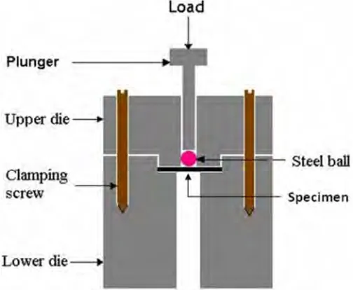
The Schematic drawing of die-punch assembly loaded with specimen, ball and plunger is shown in fig. 3. The tests were carried out in a computer controlled universal testing machine at a cross head speed of 0.1mm/min. The applied load and associated deflection were recorded using a load cell of 100kg capacity and a linear variable differential transducer (LVDT) respectively.
Fig. 3 Schematic drawing of die - punch assembly loaded with specimen, ball and plunger
Table-1
Heat treatment cycle
HT-1 1000°C-10h/oil quench to RT/700°C -16h /air cooled to room temperature. HT-2 1000°C-15h/oil quench to RT/680°C -29h /air cooled to room temperature. HT-3 925°C-8h/water quench to RT/625°C-18.5h/air cooled to room temperature.
HT-4 915°C-8h/water quench to RT/ 645°C-26h /air cooled to RT/ 615°C- 4.5h/ furnace cooled to 400°C/650-9.5h/furnace cooled to 400°C/air cooled to
room temperature.
HT-5 620°C-4.5h/ furnace cooled to 400°C / 625°C-6.5h/furnace cooled to 400°C / 650°C-9.5h/ furnace cooled to 400°C /air cooled to room temperature.
RESULTS AND DISCUSSION
The load-deflection (P-δ) graphs were obtained after testing. The fig.4 (a) shows the effect of specimen thickness for SA 333 steel. The effect of thickness can be seen more on peak load than the total deflection. This is clear from the graph that the variation in specimen thickness must be maintained within the tolerance limit specified [1]. The comparison of P-δ graphs for different heat treated specimens at room temperature along with as-received condition of RPV steel can be seen in fig. 4(b). The difference in graphs is due to change in material properties that were expected after heat treatment. The parameters which are obtained from load-deflection graphs of SPT are maximum load (Pmax), yield load (Py) and deflection at fracture (δ*). These parameters are used for calculation of
ultimate tensile strength (UTS), yield strength (YS) and fracture toughness (JIC) of the materials. A typical SPT
load-deflection graph is shown in fig.5 showing determination of Py, Pmax, δ*and four typical deformation zones. All the
three parameters were determined from each of the P-δ graphs obtained at different temperatures and directions and used for estimation of tensile properties and fracture toughness. The Pmax was used to estimate the UTS of the
material by using the following relationship given by Xinayun Mao and Hideaki Takahashi for miniaturised specimens of 3 mm diameter and 0.25 mm thickness [2].
σuts (Mpa) = 130(Pmax / t02) –320. (1)
The yield load Py was used to determine the yield strength of the material using the relationship
σy (Mpa) = 360 (Py/to2) (2)
The fracture toughness JIC was determined by first determining the equivalent fracture strain (εqf). The εqf was
estimated using δ* in the following relationship.
εqf = ln(t*/t0) = β(δ*/t0)2 (3)
The εqf was related to the fracture toughness JIC as
J1c (kJ/m2) = kεqf - j (4)
WherePmax and Pyare in kN, t*, t0 and δ*are the thickness at fracture, initial thickness of the specimen and
deflection at fracture respectively in mm and the β is a material constant determined experimentally. The k and j are constants for the material to be tested.
(a) (b)
Fig. 4 Load-deflection graphs at room temperature for (a) SA333 steel showing effect of thickness (b) heat treated specimens (HT-1 – HT-5)
Table-2
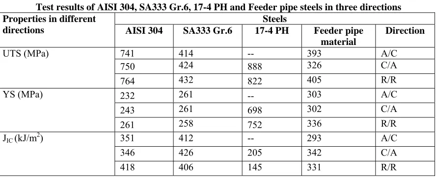
Test resultsof AISI 304, SA333 Gr.6, 17-4 PH and Feeder pipe steels in three directions Steels
Properties in different
directions AISI 304 SA333 Gr.6 17-4 PH Feeder pipe
material
Direction
741 414 -- 393 A/C
750 424 888 326 C/A
UTS (MPa)
764 432 822 405 R/R
232 261 -- 303 A/C
243 261 698 302 C/A
YS (MPa)
261 258 752 336 R/R
351 412 -- 293 A/C
346 426 205 342 C/A
JIC (kJ/m2)
418 406 145 331 R/R
Table-3
Uniaxial tension test results
Steels Properties
A533B AISI 304 SA333 Gr.6 17-4 PH
UTS (Mpa) 552 630 500 1018 YS (Mpa) -- 265 330 942
Table-4
Test results of A533B, heat treated RPV and AISI 410 steels Steels
RPV Properties at
room temperature
A533B
As-received HT-1 HT-2 HT-3 HT-4 HT-5
AISI 410
UTS (Mpa) 505 583 564 548 766 636 612 681 YS (Mpa) -- -- -- -- -- -- -- 584 JIC (kJ/m2) 261 278 305 308 276 277 337 191
The tensile properties of AISI 304, SA333 Gr.6, 17-4 PH and feeder pipe steels obtained in three directions (A/C, C/A and R/R) at room temperature did not show much appreciable variation. The estimated results are shown in table-2. This is indeed as expected in view of the isotropic nature of the materials. But the estimated results were found to be slightly different (except in the case of 17-4 PH steel) from the results obtained by uniaxial tension test as shown in table-3. It is seen from the table that the UTS values obtained by SPT technique for AISI 304 steel is higher side whereas for SA 333, 17-4 PH and A533B (table-4) steels are lower side than the tension test results. Similarly, the YS of two (SA 333 and 17-4 PH) steels are showing lower values than the values obtained from tension test. This indicates that one constant is not suitable for all types of steel and it needs more experimental work to generate a large volume of data. The JIC values estimated by SPT technique could not be compared with
standard test results because of non availability of data. But, it can be seen from table-2 that JIC values of 17-4 PH
steel are showing appreciable difference in two directions (C/A and R/R). This difference may be due to the fabrication route followed for the component. In case of heat treated materials the UTS and JIC values were found to
be different for each of the five conditions of material as shown in table-4. This difference in material properties indicates not only the effect of different heat treatment but also the efficacy of SPT technique in detecting the variation arising from heat treatments.
Determination of yield load from SPT
The determination of Py is carried out using the ‘two tangents’ method by drawing tangents to the elastic and
plastic bending portions of load-deflection graphs obtained from SPT as shown in fig.5. The point of intersection of two tangents is considered as the yield point and the corresponding load is the yield load Py [2].
Fig.5 A typical SPT load-deflection graph obtained for steel
It is to be noted that the drawing of tangents is not a straight forward matter. It calls for judgment (which is somewhat subjective) and hence can be less accurate or reliable as it is not that well defined a point on the load-deflection graph. Since, the estimation of Py is done manually with the help of geometrical conditions done on the
experimental graphs to identify the possible location where yielding could have initiated, it is very difficult to estimate it (and hence the yield stress) unambiguously in the load-deflection graph in some cases. That is why the yield strength from SPT was not estimated for few materials in the present study.
CONCLUSION
1. The tensile properties of AISI 304, SA333 Gr.6, 17-4 PH and feeder pipe steels obtained in three directions at room temperature did not show much appreciable variation. This is indeed as expected in view of the isotropic nature of the materials.
2. The variation in tensile properties obtained from two (SPT and tension test) techniques was observed. This indicates that one constant is not suitable for all types of steel.
3. The SPT results on different steels indicated that the technique is reliable enough to be used for evaluation of tensile properties and fracture toughness of irradiated materials with the help of 3mm disc specimens.
ACKNOWLEDGEMENTS
The authors wish to acknowledge Shri A. M. Likhite and Shri S. B. Deherkar for their co-operation in helping us prepare the samples for the present study.
REFERENCES
[1]. JAERI-M88-172, Recommended Practice for Small Punch (SP) Testing of Metallic Materials, September 1988.
[2]. X. MAO and H. Takahashi, “Development of Further Miniaturised Specimen of 3mm Diameter for TEM Disk (φ3mm) Small Punch Tests”, Journal of Nuclear Materials, Vol. 150, 1987, pp. 42-52.