DESIGN AND CONSTRUCTION OF AN INTERROGATION UNIT FOR FIBER BRAGG GRATING SENSOR SYSTEM
MOHD ASMU’I BIN MOHD AKIL
A thesis submitted in fulfilment of the requirements for the award of the degree of
Master of Science (Physics)
Faculty of Science Universiti Teknologi Malaysia
iii
iv
ACKNOWLEDGEMENT
I would like to express my thanks to all my supervisors; Assoc. Prof. Dr. Rashdi Shah Ahmad and Prof. Dr. Rosly Abdul Rahman for being very resourceful, inspiring, supporting and understanding during my study. I like to thanks all the staff from Physics Department (UTM) and Advanced Photonics Science Institute (UTM) especially En Nasir Bakar, En Ahmad Imbar and En Subri Ishak. Their technical support to my thesis’s project is priceless and I appreciate it very much.
Also, I would like to acknowledge my friend En Yap Yung Szen, En Sakifli and En Aizi Mat Salim for their help in term of idea, my research progress and for the moral support.
v
ABSTRACT
vi
ABSTRAK
vii
TABLE OF CONTENTS
CHAPTER TITLE PAGE
DECLARATION ii
DEDICATION iii
ACKNOWLEDGEMENT iv
ABSTRACT v
ABSTRAK vi
TABLE OF CONTENTS vii
LIST OF TABLES x
LIST OF FIGURES xi
LIST OF SYMBOLS xiv
LIST OF APPENDICES xvi
1 INTRODUCTION 1.1 General Introduction to FBG Technology 1
1.2 Measurement of Wavelength 4
1.3 Background of Problem 5
1.4 Statement of Problem 6
1.5 Scope of study 6
1.6 Statements of hypotheses 7
1.7 Objectives of the study 7
1.8 Thesis plan 7
viii
2.1.1 Passive Wavelength Demodulation System 9
2.1.2 Long Period Grating 11
2.1.3 Acousto-optic Tuneable Filter 12
2.1.4 Active Wavelength Demodulation Using Acousto-optic Tunable Filter 16
2.1.5 Wavelength Division Coupler 18
2.1.6 Highly Overcoupled Couplers 20
2.1.7 Biconical Fiber Filter 21
2.1.8 Matched-filter Interrogation 23
2.1.9 Interrogation of Wavelength Division Multiplexed FBG 26 Using Arrayed Waveguide Grating 2.2 Fiber Bragg Gratings 28
2.2.1 Theory of Fiber Bragg Gratings 29
2.2.1.1 Mode Theory for Optical Fibers 30
2.2.1.2 Coupler Mode Theory 35
2.2.2 Transfer Matrix Method 40
2.3 Fabry Perot Concept 43
2.3.1 Historical Background 43
2.3.2 Mathematical Model For The Fabry Perot Filter 45
2.3.3 Figures Of Merit 46
2.4 Motor Driven Tunable Filter 51
3 METHODOLOGY 3.1 Introduction 53
3.2 Detection Concept 55
3.3 Complete FBG Interrogation System 57
3.4 FBG Calibration 59
3.5 Calibration Interrogation System 60
3.5.1 Motor Driven Tunable Filter 60
3.5.2 Photodetector 65
3.6 Interfacing 69
ix
3.6.2 Data Acquisition and Logic 73
4 RESULTS AND DISCUSSIONS 4.1 Introduction 76
4.2 Calibration of Broadband Source and Photodetector 76
4.3 Calibration of Motor Driven Tunable Filter 87
4.4 Evaluation of The System 91
4.5 Simulation of Fabry perot FBG 97
4.6 Experimental of Fabry Perot FBG 101
5 CONCLUSIONS 5.1 Summary of findings 106
5.2 Suggestions and Recommendations 107
REFERENCES 108
x
LIST OF TABLES
TABLE NO. TITLE PAGE
3.1 Optical Specifications For Motor Tunable Filter 61
3.2 RS-232 Settings 62
3.3 Importants Command Used To Control Motor Tunable Filter 63 3.4 Optical Specifications For Motor Tunable Filter 64 3.5 Optical Specifications For Motor Tunable Filter 64
3.6 Photodetector Gain 66
4.1 Important Mark in Spectrum 79
4.2 Value a and b of Lorentzian Equation To Fit Spectrum Data 80
4.3 Total Power 83
4.4 Toggle Position of Source versus Output of InGaAs Detector 85
4.5 Voltage Output from InGaAs Detector 85
4.6 Wavelength Different Between The Wavelength Tuned by Motor Tunable Filter and Wavelength Detected by OSA 88 4.7 Results of Bragg wavelength from OSA and MTF 95
4.8 Applied Strain To The Bragg Wavelength 97
xi
LIST OF FIGURES
FIGURE NO. TITLE PAGE
1.1 A schematic representation of a Bragg grating 2 inscribed in the core of an optical fiber 1.2 Diffraction of a light wave by a grating 2 2.1 Schematic of passive wavelength demodulation system 10 2.2 Experimental set-up for fiber grating sensor interrogation. 12
The dotted boxes outline the modulation system employed in the resolution improvement experiment 2.3 Schematic diagram using acousto-optic tuneable filter 13 2.4 Experimental arrangement using AOTF 16 2.5 Experimental setup for demonstration of edge-locking AOTF 17
based AWDS for broadband light interrogated Bragg grating sensor 2.6 Diagram of strain sensor configuration using a fiber Bragg 20
grating and wavelength division coupler 2.7 Experimental setup for Bragg wavelength detection using HOCC 21 2.8 Schematic diagram of demodulation scheme 22 2.9 Matched-filter interrogation of FBG sensors 24 2.10 Experimental setup wavelength division multiplexed FBG using 27
arrayed waveguide grating
2.11 Schematic diagram of step-index fiber with cylindrical coordinates 30 2.12 Graphs of Bessel functions of the first kind for v = 0, 1, 2, 3 32 2.13 Graphs of the eigenvalue equation of step-index fiber 34 2.14 Reflection spectral response versus normalized wavelength for 39 uniform Bragg gratings witk κL=2 and κL=10
xii
2.17 Transmission of the Fabry Perot filter as a function of frequency. 47 Adjacent fringes are equally spaced in frequency
2.18 Transmission of the Fabry Perot filter indicating free spectral range 48 and bandwidth resolution as functions of resonance frequency
2.19 Variation of transmission intensity of the Fabry Perot filter for 50
different values of finesse
2.20 Motor Driven Tunable Filter Operation 52
2.21 Motor Driven Tunable Filter Spectrum 52
3.1 FBG Strain/Temperature Characteristics 54
3.2 (a)Transmission spectrum of FBG; (b)Reflection spectrum of FBG 54 3.3 Lambda Bragg by TFBG looking to the transmission TFBG 55 3.4 Lambda Bragg by TFBG looking to the reflection TFBG 56
3.5 Complete interrogation unit system 57
3.6 Unit Using Tunable Laser SourceAs a Wavelength Varies 58 3.7 Interrogation by Broadband Source And Motor Tunable Filter 59
3.8 Detecting Unit Using Broadband Source 60
3.9 Calibration of Motor Tunable Filter 61
3.10 PDA400 Responsivity 66
3.11 Calibration Photodetector 66
3.12 Broadband Source Dial Button 68
3.13 Setup for Spectrum Calibration 68
3.14 Optical Spectrum of Broadband Source 68
3.15 Setup for Photodetector Calibration 68
3.16 Serial Port Analog To Digital Interface Circuit 70 3.17 INA114 Precision Instrumentation Amplifier 71 3.18 Programming Flow Chart to Detect Maximum Amplitude 74
3.19 Software FBG Visulation System 75
4.1 Spectrum power of each dial Position; (a) to (i) 78
4.2 Power spectrum at each nine positions 82
4.3 Spectrum for nine dialled positions 84
4.4 Comparison between graph (a) and (b) 86
4.5 Integration Power versus V2 87
xiii
Filtered by Motor Driven Tunable Filter
4.7 Relationship of the Wavelength OSA and Wavelength MTF 89 4.8 Wavelength Different of Each Wavelength Tested 90 4.9 Experimental Setup for FBG Interrogation System 91
4.10 The interrogation system software 91
4.11 Spectrum of nine FBG tested using OSA and MTF; (a) to (i) 95 4.12 Comparison lambda Bragg (MTF) with lambda Bragg (OSA) 96 4.13 Setup of interrogation system used to interrogate the applied 96
Strain FBG sensor
4.14 The Bragg wavelength change due to applied strain 97 4.15 Construction of the Dual Fiber Bragg Gratings as a Fabry 98
Perot Resonator
4.16 Figure shows here (a) reflection spectrum, (b) – (j) transmission 100 spectrum of a FP FBGs with a separation length 0.5cm, 1.0cm, 1.5cm, 2.0cm, 2.5cm, 3.0cm, 3.5cm, 4.0cm and 4.5cm
xiv
LIST OF SYMBOLS
λBragg - Bragg wavelength IMG - Index Matching Gel
µε - microstrain
TLS - Tunable Laser Source FBG - Fiber Bragg Grating
FPFBG - Fabry Perot Fiber Bragg Grating
λ - Wavelength
AOTF - Acousto-optic tunable filter BFF - Biconical fibre filter
BWDM - Bandpass wavelength-division multiplexing CCD - Charge coupled device
CFBG - Chirped fibre Bragg grating DOE - Diffractive optical element
DWDM - Dense wavelength-division multiplexing ECL - External cavity diode laser
EDF - Erbium-doped fibre
EDFA - Erbium doped fibre amplifier FFP - Fibre Fabry-Perot
FFTS - Fibre fourier transform spectroscopy FSK - Frequency shift keying
FSR - Free spectral range
FTS - Fourier transform spectroscopy FWHM - Full width half maximum GRIN - Graded Index
HOCC - Highly over-coupled couplers IC - Integrated circuit
xv
LPG - Long period grating MLM - Mode-lock modulator
MZI - Mach-Zehnder interferometer OPD - Optical path difference OSA - Optical spectrum analyzer PC - Personal computer
PZT - Piezo-electric transducer RF - Radio frequency
SFBG - Superstructure fibre Bragg grating SLD - Super-luminescient diode
SMF - Single mode fibre UV - Ultra violet
VCO - Voltage controlled oscillator WDM - Wavelength-division multiplexing WS - Wavelength scanner
∆T - temperature change
∆F - applied force
ε - strain
σ - stress
n - refractive index
d - spacial period
Λ - grating pitch
neff - effective index of refraction
∆ε - strain applied
ρα - photo-elastic coefficient
ρ11, ρ12 - components of the fibre optic strain tensor
υ - Poisson’s ratio
∆L - space between Bragg grating elements
F1, F2 - pulse train frequencies
G1S - sensor grating
G1R - receiver grating
P, P1, P2 - optical power
xvi
LIST OF APPENDICES
APPENDIX TITLE PAGE
A Datasheet Photodetector 115
B Datasheet Motor Tunable Filter 116
C Matlab Simulation Code 118
D Calibration Motor Tunable Filter 120
E Data Interrogation System 122
CHAPTER 1
INTRODUCTION
1.1 General Introduction to FBG Technology
The research and development of precise measurement using optical sensor technology gives birth to a Fiber Bragg Grating (FBG) in 1978 (Hill K. O. et. al., 1993). It was discover by Ken Hill and colleagues at Canada’s Communications Research Center (CRC; Ottawa, Canada) when they studying for a nonlinear effects in germanium doped silica fiber.
2
Figure 1.1: A schematic representation of a Bragg grating inscribed in the core of an optical fiber
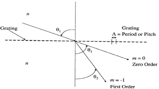
The working principle of a fiber Bragg grating is it an optical diffraction grating with a light wave incident on the grating at an angle of θ1, can be described by the grating equation given by Hecht (2002) as
n sin θ2 =n sinθ1 +m(λ/Λ) (1.1)
Where θ2 the angle of the diffracted wave, n is the refractive index of the media,
λ is the incident wavelength, Λ is the spatial period of the grating, and the integer m determines in the diffraction order as shown in Figure 1.2 (Van L.L. 2003). This
equation predicts the direction for which constructive interference occurs and is used for determining the wavelength at which a grating most efficiently coupled light between two modes.
Figure 1.2: Diffraction of a light wave by a grating
Λ
Broadband Spectrum
λ=λ1+λ2 Fiber Bragg Grating
Transmission Spectrum, λ1
Reflection Spectrum,
3
For a conventional fiber Bragg grating, the periodicity of the index modulation has a physical spacing that is one half of the wavelength of light propagating in the waveguide (it is phase matching between the grating planes and incident light that results in coherent back reflection) (Othonos A. and Kalli K., 1999).
Reflectivity’s approaching 100% are possible, with the grating bandwidth tailored from typically 0.1 nm to in excess of tens of nanometers. These characteristics make Bragg gratings suitable for telecommunication where they are used to reflect, filter or disperse light. Fiber lasers capable of producing light at telecommunications windows utilize Bragg gratings in forming both the high-reflectivity end mirror and output
coupler to the laser cavity, realizing an efficient and inherently stable source (Grattan K.T.V. and Meggitt B.T., 2000).
On top of that, the advantage of using the Fiber Bragg grating (FBG) sensors have received significant interest in recent years because they have a number of distinguishing advantages compared with other implementations of fiber-optic sensors (Rao Y. J. et. al., 1995). The main advantage is the two characteristics of Bragg gratings written in Ge-doped silica fibers make them particularly attractive for sensing
applications. First, the gratings are intrinsic; thus they may be inserted in small or complex structures with minimal disturbance of the structure. Second, the measurand causes a wavelength shift of the light reflected by the grating. Since the sensed signal is naturally wavelength-encoded, the sensed information is independent of source power fluctuations and losses in the connecting fibers and couplers (Weis R. S., 1994). Other advantages are:
i. They give an absolute measurement insensitive to any fluctuations in the
irradiance of the illuminating source, as the information is obtained by detecting the wavelength shift induced by the measurand (Morey W. W. et. al., 1991). ii. They can be written into the fiber without changing the fiber diameter, making
4
iii. They can be mass-produced with good repeatability, making them competitive with conventional electrical sensors (Askins C. C. et. al., 1994).
iv. Many gratings of FBG can be serially arranged along a fiber to create a quasi-distributed sensor array. These quasi-distributed and multiplexed fiber-grating-based sensing schemes have been proposed in many ways that have been intensively investigated for use with fiber-optic sensors, such as wavelength-division multiplexing (WDM), frequency-division multiplexing (FDM), time-division multiplexing (TDM), and their combinations (Kersey A. D. et. al., 1994), making quasi-distributed sensing practically feasible. These systems are illuminated using a spectrally broad-band source and each grating reflects a narrow-band portion of the incident light spectrum. A measurand-induced change of an individual grating’s period changes the narrowband wavelength reflected by that grating. The wavelength shift of the grating-reflected light is detected at the output. (Weis R. S., 1994)
1.2 Measurement of Wavelength Shift
The detection of this ‘wavelength shift’ has been the subject of considerable research and several techniques have been developed. Two techniques that using filter as their main components to detect the ‘wavelength shift’ are using bulk optic filters whose fractional power transmitted are linear functions of wavelength (over the wavelength range of interest) (Melle S. M. et. al., 1992), and the other with a fused biconical coupler (Davis M. A. et. al., 1994).Another techniques uses matched
5
scheme, the MZ converts the wavelength shift of the grating reflected light to a phase shift and then detects that phase shift. (Weis R. S., 1994)
1.3 Background of Problem
The primary drawback of the interrogation system for FBG sensor lies in the detection of wavelength shift ∆λ of the FBG sensor return. This function can be provided by a conventional spectrometer or monochromator, or by a more simple
arrangement involving a dispersive element coupled with an image array, such as a CCD detector array. The problem is the system are unapplicable due to bulk-optical nature, size, lack of ruggedness and limited resolution capability (A. D. Kersey, 1992), (Rao Y. J. et. al., 1995).
In order for these gratings to be used in a practical sensor system, the determination of the peak wavelength of the narrow-band spectrum, on the order of angstroms, reflected from such a grating is of particular importance (Melle S. M. et. al., 1992).
However, the cost of the optical interrogation system remains high. This points of a future where the cost of a complete system is dictated by the interrogation method rather than by the gratings themselves. The majority of Bragg gratings are interrogated in one of two ways. (Fallon R W, 1998):
(a) By a tunable filter such a Fabry–Perot. These systems are moderately expensive, good for measuring static and quasi-static measurands with a resolution of about 10 µε and are particularly suitable for wavelength multiplexing.
6
1.4 Statement of Problem
A key issue with FBG sensors is it needs a high-resolution device for the detection of wavelength shift (or Bragg wavelength, λB) that had a bandwidth ~0.1
nm (Rao Y. J. et. al., 1996). In the lab, usually the Optical Spectrum Analyzer (OSA) was used to detect the wavelength shift. Although OSA has a capability of scanning to a wide range spectrum and can achieve high-resolution wavelength detection, but it is not applicable to be used with the FBG sensor on the field work. This is because the OSA is not rugged, fragile, not robust device for sensing environment, bulky in term of size and portable. Also the OSA are scanning the power in the wavelength range, so the
wavelength shift is manually determine according to FBG sensor setup either the reflection or the transmission power. This is a disadvantage of time consuming to detect the wavelength range.
1.5 Scope of study
The highlight of the research was the development of an interrogation unit for FBG sensor with the center wavelength of 1300nm. The work flow of this research includes:
i. Design and construct setup for FBG detection unit of wavelength 1290 nm (1270 nm – 1310 nm) using optical and electronic circuit
- Optical - using Motor-Driven Tunable filter and Photodetector as an optical scanner
- Electronic – build interface card Serial Port from ADC/DAC ADS1212 to control Motor-Driven Tunable Filter and capture data from Photodetector using computer
ii. Software development using Visual BasicI® for data acquisition and finding wavelength shift
7
1.6 Statements of hypotheses
The hypotheses made are as follows;
1. the wavelength shift can be detected or defined by interrogation unit detecting using two methods: detect the peak of highest power in the transmission spectrum of fiber Bragg grating (FBG) and the peak of lowest power in reflection spectrum of FBG
2. Besides using a fiber Bragg grating (FBG) as a fiber optic sensor,
theoretically it also has a capability as a high resolution interrogation unit. 3. an improvement of interrogation unit based on Fabry Perot (FP) system by
using dual FBG to make Fabry Perot FBG (FPFBG)
1.7 Objectives of the study
The objectives of this study are;
1. To design and construct a portable high-resolution an interrogation unit for Fiber Bragg Grating sensor,
2. To unsure the interrogation unit should be low-cost, simple system and directly give the Bragg wavelength value without needing to analyze or show the whole spectrum,
3. To determine the optimum parameter of Fabry Perot Fiber Bragg Grating in terms of length of resonator, free spectral range, minimum resolvable bandwidth, finesse and contrast factor to achieve tunable filter replacing Motor-Driven Tunable Filter for interrogation unit,
4. To test the interrogation unit to a complete sensor system.
1.8 Thesis plan
8
civil monitoring, telecommunication and also surveillance. This chapter also give an inside problem to the FBG that show the important of this study to make FBG sensing system are feasible to real life application.
The second chapter deals with the literature review on the previous studies done by research all over the world in the interrogation unit field. It highlights the most important system and setup cover up from 1992 until 2007 such as by using highly overcoupled couplers, mode-locked interrogation, biconical fiber filter, bandpass wavelength multiplexing, pseudoheterodyne demodulation technique, acousto-optic tunable filter and others more method describe detailly in this chapter. Also, this chapter discusson the detailed theory of FBG including the mathematical model to describe the physical meaning inside the grating and the method to simulate or design of a FBG. The focuses of this chapter also include the background theory of this whole research work on how the FBG itself can be used to develop and constructed the effective interrogation unit. Consolidation to the used of a Fabry Perot phenomenon as an added advantage to increase the performance of FBG interrogation is also distinct.
The third chapter states the experimental and measurement techniques which includes research design and the apparatus used for both optical and electrically. The parameters and physical measurements are defined.
The fourth chapter deals with analysis of the system performance. The characteristics of FBG as a main medium for interrogation unit are clarify both
experimentally. Because of a fabrication limitation, the Fabry Perot fiber Bragg grating (FPFBG) only analyses using mathematical modelling and simulation only. In the end of this chapter, the results of a demonstration interrogation unit in practical application are presented.