A Novel Method for Reference Signals Generationapplied
to Upqc-Phev for Grid Integration of Wecs-Scig
K . RAGHU RAM 1
, B.
ROOPIKA2 1Professor, Laqshya institute of tech. & sciences, Khammam
2PG Scholar, Laqshya institute of tech. & sciences, Khammam
Abstract- This study proposes a combined operation of the Unified Power Quality Conditioner (UPQC) with wind power generation system considering investment cost. The proposed system consists of a series inverter, a shunt inverter and an induction generator connected in the DC link through a converter. The proposed system can compensate voltage sag, voltage interruption, harmonics and reactive power. The speed of the induction generator is controlled according to the variation of the wind speed in order to produce the maximum output power. The investment cost of proposed system is compared with investment cost of separated use of UPQC and wind energy conversion system (WECS) and the economic saving due to use of proposed system is estimated. The validity of the proposed system is verified by the results of computersimulation.
Keywords ñ series inverter, UPQC
I. INTRODUCTION
One of the most interesting structures of energy conditioner is two back-to-back connected DC/AC fully controlled For example, they can function as active seriesand shunt filters to compensate simultaneously load current harmonics and supply voltage fluctuations. In this case, the equipment is called Unified Power Quality Conditioner (UPQC).
An active shunt filter is a suitable device for current-based compensation. It can compensate current harmonics and reactive power. The active series filter is normally used for voltage harmonics and voltage sags compensation. The UPQC, which has two inverters that share one DC link capacitor, can compensate the voltage sag and swell, the harmonic current and voltage and control the power flow and voltage stability. Nevertheless, UPQC cannot compensate the voltage interruption due to lack of energy source in its DC link.
This study, a new configuration of UPQC is proposedthat has a Wind Energy Generation System (WEGS) connected to the DC link through the rectifier as shown in Fig. 1. The significant advantage of this configuration in compare with separate operation of UPQC and wind energy generation system is reduction in using of one inverter and use of shunt inverter of UPQC as a WEGS`s inverter. The UPQC can compensate the voltage interruption in the source, while the WEGS supplies power to the source and load or the load only. There are two operation modes in the proposed system. The VA rating of series and shunt inverters of UPQC are estimated for proposed system. The investment cost of proposed system is compared with investment cost of separateduseofUPQCandWECSusingtheVArating
calculations and the economic saving due to use of proposed system is estimated.
II.PROPOSEDSYSTEM
In the diagram, there are six main parts in proposed system: wind turbine, induction generator, maximum power point tracking which controls induction generator speed, PWM rectifier, shunt inverter and series inverter of UPQC.
The modeling of each section is discussed separately and then the overall model is investigated.
Fig.1.proposed system
A Wind turbine: The output power from a wind turbine can be expressed in below:
http://edupediapublications.org/journals/index.php/IJR/
P a g e | 4439 where, Îopt is the optimized tip-speed ratio which ‚ is zero(2) and C
P is maximum. Hence, to fully utilize the wind energy, Î should be maintained at Îopt, which is determined from the blade design. Then from Eq. 2:
(3)
where, Î is tip-speed ratio, VWIND is the wind speed, R is bladeradius,˘r istherotorspeed(radsec
-1
),Ͽistheair
density, CP is the power coefficient, PM is mechanical output power of wind turbine and TM is the output torque of wind turbine.
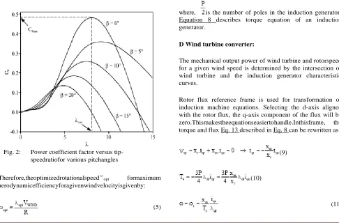
The power coefficient CP depends on the pitch angle ‚, the angleatwhichtherotorbladescanrotatealongitslongaxis andtip-speedratioÎgivenbyEq.4:
(4)
where, ‚is the blade pitch angle. For a fixed pitch type, the valueof‚issettoaconstantvalue
B Maximum power point tracking:
In this study, the pitch angle is kept at zero until the nominal power of the induction generator is reached. At high wind speeds, the pitch angle is increased to limit the input power .
Fig. 2: Power coefficient factor versus tip-speedratiofor various pitchangles
Therefore,theoptimizedrotationalspeed˘opt formaximum aerodynamicefficiencyforagivenwindvelocityisgivenby:
(5)
(6)
where, PM max is maximum mechanical output power of wind turbine at a given wind speed.
Once the wind velocity VWIND is measured, the reference speed for extracting the maximum point is obtained from Eq. 5.
C Induction generator:
In this study, a fifth order model for induction generator simulation is used. To overcome the complexity of themodel, usually Park`s transformation is used. The transformed induction machine equations are described below:
(7)
(8)
where, is the number of poles in the induction generator. Equation 8 describes torque equation of an induction generator.
D Wind turbine converter:
The mechanical output power of wind turbine and rotorspeed for a given wind speed is determined by the intersection of wind turbine and the induction generator characteristic curves.
Rotor flux reference frame is used for transformation of induction machine equations. Selecting the d-axis aligned with the rotor flux, the q-axis component of the flux will be zero.Thismakestheequationseasiertohandle.Inthisframe, the torque and flux Eq. 13 described in Eq. 8 can be rewritten as:
(9)
(10)
where, Tr is time constant of rotor and equals .
(12)
In case of a sag when VS2<VS1, where x denotes the p.u. sag:
(17)
to maintain constant active power under the voltage sag condition as explained in (1):
. This approach simplifies the induction machine control. The model is very similar to a separately excited DC machine where the flux depends on the field current and the torque is proportional to the flux and the armature current. The main problem associated with field oriented control is the requirement to estimate the flux axis angle. This is done eitherbymeasuringthefluxattwodifferentpoints(with905 displacement), or estimating through rotor speed measurement. In this study, flux axis angle Ë is calculated through rotor speedmeasurement.
thereforeseriesinverterVAratingequalsto:
Injected current through shunt inverter is:
(18)
(19)
(13)
(20)
The wind turbine converter is designed to control the rotational speed in order to produce the maximum output power, where the indirect vector control is used. The control part consists of a speed controller and the d-q current controllers. The d-axis current component is generally set to maintain the rated field flux in the whole range of speed, while the speed loop will generate the q-axis current component through a PI controller to control the generator torque and speed at different wind speed as shown in Fig. 3
therefore shunt inverter VA rating equals to:
(a) Block Diagram OFUPQC:
(21)
III. VARIATING CALCULATIONOFSHUNT 0AND
SERIESINVERTER
Volt Ampere (VA) rating of series and shunt inverters of UPQC determines the size of the UPQC. The power loss is also related to the VA loading of the UPQC. Here, the loading calculation of shunt and series inverters of UPQC with presence of DG at its DC link has been carried out on thebasisoflinearloadforfundamentalfrequency.
The load voltage is to be kept constant at Vop.u. irrespective of the supply voltage variation:
(14)
The load current is assumed to be constant at the rated value:
(15)
Assuming the UPQC to be lossless, the active power demand in the load remains constant and is drawn from the source:
(16)
(b) Series inverter ofUPQC:
http://edupediapublications.org/journals/index.php/IJR/
P a g e | 4441 rectifier when supply is drawn from the main source. It alsoact as a inverter during supply inject from dc link to main supply. Thus this converter act as a rectifier as well as inverter depends upon the requirements.
IV.Modes ofoperation:
There are two modes of operation involved and they are
Mode 1: (0˚ to 180˚)
During this mode, switches S1 and S2 is turned ON which yields to the positive half cycle of the output AC voltage waveform.
Mode 2: (180˚ to 360˚)
During this mode, switches S3 and S4 is turned ON which yields to the negative half cycle of the output AC voltage waveform.
Rectifier operation:
A bridge rectifier is used to convert input AC voltage into DC voltage. The circuit diagram of a Full wave Rectifier is
givenbelow:
The full wave a rectifier operates based on two different modes. They are
Mode 1: (0 to t/2)
During the positive half cycle of the input AC voltage, switch M1 and M2 is reverse biased. But M and M3 is forward biased and hence it conducts.
Mode 2: (t/2 to t)
During the negative half cycle of the inputAC voltage, Diode M and M3 is reverse biased. But M1 and M2 is forward biased and hence it conducts. Thereby the direction of current through the load is maintained in the same direction throughout thetime.
Available online:
http://edupediapublications.org/journals/index.php/IJR/
P a g e | 4442Modes of operation:
There are two modes of operation involved and they are
Mode 1: (0˚ to 180˚)
During this mode, switches S1 and S2 is turned ON which yields to the positive half cycle of the output AC voltage waveform.
Mode 2: (180˚ to 360˚)
During this mode, switches S3 and S4 is turned ON which yields to the negative half cycle of the output AC voltage waveform.
V. SIMULATIONRESULTS:
LINE MODEL WITHOUT COMPENSATION CIRCUIT
VOLTAGE ACROSS LOAD -2 AND LOAD-1
Real power
Reactive power
LINE COMPENSATION CIRCUIT WITH ADDITIONAL upqc
VOLTAGE ACROSS LOAD -2 AND LOAD-1 at alpha =0 degree
Real power at alpha =0 degree
Reactive power at alpha =0 degree
VOLTAGEACROSSLOAD-2ANDLOAD-1atalpha=36 degree
Real power at alpha =36 degree
Reactive power at alpha =36 degree
VOLTAGE ACROSS LOAD -2 AND LOAD-1 at alpha =72 degree
Real power at alpha =72 degree
Reactive power at alpha =72 degree Firing
angle (Degree)
Real power (MW)
Reactive power(MVAR)
0 1.099e6 0.322e6
36 1.367e6 0.3791e6
72 1.841e6 0.452e6
VI.CONCLUSION:
Available online:
http://edupediapublications.org/journals/index.php/IJR/
P a g e | 4444sag and power flow control .Thus the performance of the system is improved using facts device
REFERENCES:
1. Basu, M., S.P. Das and G.K. Dubey, 2007. Comparative evaluation of two models of UPQC for suitable interface to enhance power quality.
Elec.Powersyst. Res.,77:821-830.
2. Cavalcanti, M.C., G.M.S. Azevedo, B.A. Amaral and F.A.S. Neves, 2005. A Photovoltaic generation system with unified power quality conditioner function. 31stAnnual conference of IEEE Industrial
Electronics society, Nov. 6-10, IEEE, Brazil,pp:750-755.
3. Datta, R. and V.T. Ranganathan, 2002. Variable-speed wind power generation using doubly fed wound rotor induction machine; A comparison with alternative schemes, IEEE Trans. Energy Convers, 17: 414-421.
4. Han, B., B. Bae, H. Kim and S. Baek, 2006. Combined operation of unified power quality conditioner with distributed generation. IEEE Trans. Power Del.,21:330-338.
Mr. K . RAGHU RAM received his B.tech degree in electrical & electronics engineering from JNT university Hyderabad, AP in 1979, Mtech (electrical , power systems ,engineering)degree in electrical & electronics engineering from JNT university Hyderabad, AP in 1983. He received his P.hD from JNTU Hyderabad AP . Presently he is wornking as an professor and Principal at Laqshya institute of tech. & sciences, khammam, Telangana. He has six publications in international journals. He is guiding unergraduate , post graduate and P.hD students. His area of interest includes six phase transmission , micro grids, power systems stability etc.
Email id :[email protected]
BATHINENI ROOPIKA CHOWDARY (POWER ELECTRONICS ) PURSUING In laqshya Institute of Technology sciences ,TALIKELLA(V) ,KHAMMAM, TELANGANA, INDIA.