A Pre Congestion avoidance for ISO Based
ATC Computations in a Modern Power
System Network
Gopikrishnan M, D.Baskar
Assistant Professor, Dept. of EEE, Bharath University, Chennai, Tamil Nadu, India Assistant Professor, Dept. of EEE, Bharath University, Chennai, Tamil Nadu, India
ABSTRACT: One of the main function of ISO to control the power transactions and avoid overloading of the transmission lines beyond their thermal loading megavolt-ampere (MVA) limits in a restructured power system. For this, ISO has to update periodically a real-time index termed available transfer capability (ATC). The methods reported to date for ATC determination are unable to cater to either the accuracy or the online CPU time requirements when the system is a large one. This paper proposes a novel method with the full details for determining Available Transfer Capacity in a large power system from only three input variables through fuzzy modelling. The method is validated through extensive simulation tests on the standard IEEE 24-bus reliability test system (RTS), and comparison with an ac load flow-based conventional method using the same array of transactions, base cases, and generation/line outages.
KEYWORDS: Deregulation,Available Transfer Capability, electricity market structures, fuzzy logic, power system analysis, power system control.
I. INTRODUCTION
THE experience [1] gained since 1996 until now has turnedthe deregulation of power industry into an almost mature
reality. In a deregulated system, the generation and distribution companies (i.e., market players) engage in transactions (i.e., selling or buying electricity) through a competitive bidding process administered by an agency known as power exchange apart from the transactions through bilateral negotiations. Every intended transaction is communicated to the transmission network operator termed independent system operator (ISO). The transactions are evaluated by ISO on the basis of an index termed available transfer capability (ATC) [2]. The bus at which a generation company sells (injects) power is termed source, and the one at which a distributor buys (extracts) power is called “sink.” ATC between a given source-sink pair is the highest allowable size of a transaction over and above the already committed uses of the transmission system (i.e., existing base case) so that no line is overloaded in excess of its thermal loading limit megavolt-ampere (MVA) when the system is in steady-state condition. ATC is computed in real time at periodic intervals for each source-sink pair separately considering the base case that exists just before the current interval.
ISSN (Print) : 2320 – 3765 ISSN (Online): 2278 – 8875
I
nternational
J
ournal of
A
dvanced
R
esearch in
E
lectrical,
E
lectronics and
I
nstrumentation
E
ngineering
(An ISO 3297: 2007 Certified Organization)
Vol. 4, Issue 4, April 2015
A number of methods have been reported to date in literature for ATC determination. The continuation power-flow (CPF) methods [4]–[7] repeat full-scale ac load flow solution for each increment (above the base case value) of the load at sink bus until any line in the system is overloaded. Although accurate, these are not real-time compatible for large systems. The dc load-flow-based methods [3], [8], [9] are a bit faster than their ac counterparts but model only real power flow (in megawatts) in the lines rather than MVA, and assume the network to be loss free. The methods based on power transfer/outage distribution factors [10]–[12] can cater to only the scenarios that are too close to the base case from which the factors are derived. The stochastic methods [13], [14] are more suited to planning stage. The reported [15] artificial neural network (ANN) method requires a large input vector so that it has to oversimplify determination of ATC by limiting it to a special case of power transfer to a single area from all of the remaining areas. So this method is unable to track down the bus-to-bus transactions, which is the true spirit of deregulation.than that by other artificial intelligence (AI) techniques (such as ANN, expert system, etc.). Another advantage is that fuzzy logic can capture uncertainties inherent in an incomplete or reduced set of data. It is noteworthy that rigorous mathematics intensive conventional methods have none of these two advantages.
Fuzzy logic has successfully been used in many power system problems [17]. Of course, the way this is applied and exploited to advantages depends on the problem in particular. However, to date, no results appear to have been reported on the application of fuzzy logic for ATC determination.
In this paper, the authors have developed a method that applies fuzzy logic in the determination of ATC in a large system. The proposed fuzzy method has been tested extensively for computing ATCs between a number of source-sink pairs in the standard IEEE 24-bus reliability test system (RTS). The method has also been compared with a full-scale ac load flow-based method in terms of accuracy and CPU time for evaluating ATCs considering the same array of transactions, base cases, and outages.
II. PROPOSED METHOD
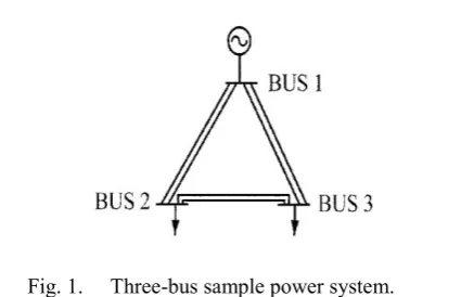
The development process of the method proposed for deter-mining ATC in a large system can best be illustrated beginning with a small (three-bus) power network shown in Fig. 1. Let the ATC between buses 1 (source) and 2 (sink bus) be evalu-ated. Power injected at bus 1 will flow to bus 2 through path „1–2‟ as well as through „1–3–2‟. The authors introduce path „1–2‟ as the “direct path,” „1–3–2‟ as the “indirect path,” and bus 3 as the “neighboring bus.” Notably the direct path has the less impedance and it shares more flow. The indirect path via the neighboring bus has the higher impedance, and it shares less flow. Consideration of the existing (base case) loads/generations at sink and neighboring buses (i.e., only two inputs can help fuzzy determination of the ATC between a pair of source-sink in an exclusively three-bus system). But in any large system with a higher number of buses, usually more than one electrical path shares the flow of power from a source bus to a sink one. This gives rise to a number of major differences that impacts ATC determination in a large system.
A. Differences Between a Large and a Three-Bus System
The following are the major differences.
i) There are a number of candidate paths and buses that can be labeled as “indirect path” and “neighboring bus” cor-responding to a given source–sink pair in a large system.
ii) For a given system topology, a transaction (power transfer) between any two buses of a large system is influenced by loads at various buses, and affects the flows in many lines to different extents depending upon the operating condition.
Fig. 1. Three-bus sample power system.
iv) The physical characteristics of an exclusively three-bus power system are easily tractable so that a set of rules can be developed to infer a fuzzy value (i.e., linguistic attribute) of ATC directly from fuzzy values of inputs. Eventually a single crisp (i.e., numerical) value of ATC is obtained combining the fired rules through a process what is known as defuzzification. This way of making inference is termed Mamdani fuzzy model [16]. But the characteristics and interactions among many buses and lines in a large system are not tractable simply on the basis of intuition. So ATC evaluation in a large system entails an alternative rule-base.
B. Identification of Indirect Path and Neighboring Bus
For a given source–sink pair, the least “indirect path” is traced using line impedance data. The one having the least impedance among all the possible indirect paths is chosen.
If there are a number of buses on the chosen indirect path between a source and a sink then the bus immediately after the source is labeled as the neighboring bus. However, if this bus has mere a load but no generator connected to it whereas a next bus on the same path is generator connected, then the latter will be preferred as the neighbor. This is because a generator connected bus influences a transaction more than what simply a load bus does. So its choice as the neighbor will provide more explicit information that will enhance accuracy in the determination of ATC.
It should be noted that tracing the indirect path and the neigh-boring bus for each source–sink pair can always be made in of-fline mode by an algorithm that would use the network topology and parameters available in the database of a system.
C. Catering to System Operating Conditions and Outages
A unified index has been proposed and labeled as “loading index” ( ) to represent a given operating scenario of a large power system taking into account demands at all the buses and information on generation/line outages. This index is defined as in (1)
(1)
where is demand (MW) at bus , is the total number of buses, and is the thermal loadability (MVA) of the line having the highest limit in the system.
ISSN (Print) : 2320 – 3765 ISSN (Online): 2278 – 8875
I
nternational
J
ournal of
A
dvanced
R
esearch in
E
lectrical,
E
lectronics and
I
nstrumentation
E
ngineering
(An ISO 3297: 2007 Certified Organization)
Vol. 4, Issue 4, April 2015
integer value (e.g., ) corresponding to the particular
category under which ATC is being determined.
It is noteworthy that if the system demand that may have a large MW value is added with a small integer the latter‟s en-tity will be masked. So the former is normalized through divi-sion by a factor 1.5 as in (1). The choice of 1.5 as mul-tiplier reflects a fact that if there were only one candidate as the indirect path between a certain source–sink pair, and the base case were with no load at any bus, then the transferable maximum power would have been about 1.5 times the thermal loading limit of the direct path. Multiplication of by “2” in (1) is mainly to make two successive categories‟ loading indexes ( ) distinct.
D. Number of Input Variables
Based on the details explained in Sections II-A to II-C, ATC between a given pair of source-sink buses in a large system is determined using only three inputs. These are, respectively, the sink bus injection , the neighboring bus injection , and the loading index ( ) under the corresponding base case. The sink and neighboring bus injections are the differences between respective local generation and demand in MW.
E. Fuzzification of Inputs
Fuzzy method is presented in literature using a more descrip-tive form rather than formal mathematics. The authors have pre-sented precisely various steps using a coherent and unified set of mathematical expressions in this and subsequent sections.
Each of the inputs is converted from a single crisp value into a maximum of two fuzzy values using the widely used [16] tri-angular functions that may overlap with one another as in Fig. 2. The -axis in Fig. 2 represents the crisp values of th input while the -axis shows “membership grade” that may vary from 0.0 to 1.0. Each triangle has a fuzzy attribute that can be coded by a linguistic variable (e.g., “low”) or a number implying level of fuzziness (e.g., 1). However, for the sake of mathemat-ical representation, a number is used. The total number of such
Fig. 2. Triangular membership function for 5th input.
F. Inference on ATC
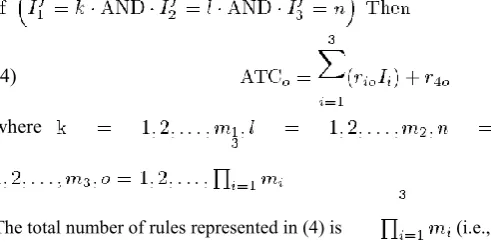
Due to the reasons mentioned in Section II-A, the rule-base relating ATC to the inputs for a large system is developed using Sugeno fuzzy model [16]. A set of first-order polynomial equa-tions is used to infer a crisp value of ATC from crisp values of three inputs. Each polynomial has four (i.e., one more than the number of inputs) coefficients ( ‟s), and is applied subject to a particular combination of fuzzy values (attributes) of the inputs. Equation (4) shows the full set of rules
(4)
where
.
The total number of rules represented in (4) is (i.e.,
product of the number of fuzzy attributes for each input).
It should be noted that a given set of crisp values for the three
inputs will not fire all of the rules rather number of rules when (i.e., one to eight rules). This is because,
as shown in (2), each input‟s crisp value has a maximum of two fuzzy values. The required overall crisp value ATC is obtained as in (5) that uses weighted average of the individual crisp out-puts from each of the fired rules, that is
(5)
where “ ” implies each of the fired rules, and is as in (6)
ISSN (Print) : 2320 – 3765 ISSN (Online): 2278 – 8875
I
nternational
J
ournal of
A
dvanced
R
esearch in
E
lectrical,
E
lectronics and
I
nstrumentation
E
ngineering
(An ISO 3297: 2007 Certified Organization)
Vol. 4, Issue 4, April 2015
(2)whereusing (3), respectively, for the three inputs‟ fuzzy values (i.e.,, and are the membership grades calculated
where (i.e., for ATC determination), , and, andfuzzy premise) of rules given by (4). ) that are also used in the conditional part (termed
are, respectively, , and .
The membership grade corresponding to each fuzzy
G. Determination of Polynomial Coefficients
value of a given crisp input can be obtained using (3)
ATC for a given source–sink pair can be obtained by online implementation of (1) to (6). However, “ ” coefficients as re-quired in (4) should be made available. The total number of
(3)these coefficients is .
The coefficients are determined by an offline procedure where j implies the numbers picked up by the th input‟s fuzzy [16] that is termed adaptive network-based fuzzy inference sys-value as in (2). tems (ANFIS). A set of training patterns (total number is )
V. CONCLUSION
This paper has proposed a method that applies for the first time ever, fuzzy logic in determining ATC in a large deregulated power system. The substantial differences between a small and large power network have been taken into accountthrough identifying only three input signals (i.e., sink bus load, neighboring bus injection, and an appropriately defined loading index) for ATC between each source-sink pair, and using Sugeno fuzzy model. The proposed method has adequately been able to exhibit generality in its performance when tested extensively on the standard IEEE 24-bus RTS, and compares well against a full-scale ac load-flow-based method for the same array of source-sink pairs, base case loadings, and generation/line outage scenarios. The developed method determines in one shot the ATC between a source-sink pair requiring only three input signals, firing a maximum of 8 out of 45 rules, and using two sets of 180 output coefficients (consequent parameters) irrespective of system size. The general characteristics that exist in any large network have been exploited by the proposed method in choosing only three inputs, five fuzzy attributes for the injection input, and three attributes for each of the other two inputs. This limits the number of rules to only 45. The neighboring bus can always be predetermined (i.e., offline) for each source-sink pair in a given system. The two sets of 180 consequent parameters are also obtained offline, respectively, using a mixed set of only about 200 training patterns on base load variations and generation outage categories, while another mixed set of only 100 training patterns on crucial and noncrucial line outage categories. The proposed method’s requirement of two separate sets of coefficients, respectively, for line outage and other categories is quite normal just as the conventional load-flow method which also requires separate Jacobian matrices whenever the topology changes.
size while the load-flow-based ATC determination method’s CPU time is directly proportional to the size despite exploitation of sparse structure of the system. This is because the load-flow method requires for ATC between each source-sink pair 2 number of inputs when is the total number of buses in the system. But the proposed fuzzy method requires only three inputs irrespective of system size. Even the numbers of rules and parameters related to fuzzy model are system size independent. So when applied on a larger system, the proposed method’s speedup ratio relative to a load-flow method will definitely escalate far above 2 in proportion to the size of the system. This will enable the proposed method to determine ATC considering more cases and contingencies than the conventional load-flow method in a given interval of time when using the same processor.
Use of more than 100-MW increment in sink bus load by the conventional method may reduce its CPU time but will seriously compromise its accuracy inATC determination. On the contrary, use of a small increment (e.g., 10 MW will enhance its accuracybut increase the CPU time requirement by a factor of about
10). But the proposed method’s accuracy can always be further improved without any increase in its CPU time irrespective of system size. This is because the output coefficients (consequent parameters) it requires can be obtained offline using training patterns taken from past real data or a load-flow method that uses 10-MW increment in sink bus load. The proposed method can easily be extended to provide additional outputs besides ATC at trivial computational costs. Currently, the authors are investigating into extending the method to determine the VAR supports that may be required occasionally to avoid any voltage collapse while a transaction takes place between a source-sink pair.
REFERENCES
[1] M. Ilic, F. Galiana, and L. Fink, Power Systems Restructuring: Engineeringand Economics. Norwell, MA: Kluwer, 1998.
[2]Sukumaran V.G., Bharadwaj N., "Ceramics in dental applications", Trends in Biomaterials and Artificial Organs, ISSN : 0971-1198, 20(1) (2006) pp.7-11. [3] Available Transfer Capability Definitions and Determination (1996).
[Online]. Available: http://www.nerc.com
[4] Selva Kumar S., Ram Krishna Rao M., Balasubramanian M.P., "Chemopreventive effects of Indigofera aspalathoides on 20-methylcholanthrene induced fibrosarcoma in rats", International Journal of Cancer Research, ISSN : ISSN: 1811-9727, 7(2) (2011) pp.144-151.
[5] G. Hamoud, “Feasibility assessment of simultaneous bilateral transactions in a deregulated environment,” IEEE Trans. Power Syst., vol. 15,pp. 22–26, Feb.
2000.
[6]Menon R., Kiran C.M., "Concomitant presentation of alopecia areata in siblings: A rare occurrence", International Journal of Trichology, ISSN : 0974-7753, 4(2) (2012) pp.86-88.
[7] M. H. Gravener, C. Nwankpa, and T.Yeoh, “ATC computational issues,” in Proc. 32nd Hawaii Int. Conf. Syst. Sci., Maui, HI, 1999, pp. 1–6.
[8]Rayen R., Hariharan V.S., Elavazhagan N., Kamalendran N., Varadarajan R., "Dental management of hemophiliac child under general anesthesia", Journal of Indian Society of Pedodontics and Preventive Dentistry, ISSN : 0970-4388, 29(1) (2011) pp.74-79.
[9] G. C. Ejebe, J. Tong, J. G. Waight, J. G. Frame, X. Wang, and W. F.
Tinney, “Available transfer capability calculations,” IEEE Trans. Power Syst., vol. 13, pp. 1521–1527, Nov. 1998.
[10]Shanthi B., Revathy C., Devi A.J.M., Subhashree, "Effect of iron deficiency on glycation of haemoglobin in nondiabetics", Journal of Clinical and Diagnostic Research, ISSN : 0973 - 709X, 7(1) (2013) pp.15-17.
[11] M. H. Gravener and C. Nwankpa, “Available transfer capability and first
order sensitivity,” IEEE Trans. Power Syst., vol. 14, pp. 512–518, Feb.1999.
[12] A. Khairuddin and S. S. Ahmed, “Slack-load bus pair technique using
full AC load flow algorithm for on-line determination of ATC,” Proc. 2nd World Eng. Congr., pp. 25–28, July 22–25, 2002.
[13] G. Hamoud, “Assessment of available transfer capability of transmission systems,” IEEE Trans. Power Syst., vol. 15, pp. 27–32, Feb. 2000.
[14] M. D. Ilic,Y. T.Yoon, and A. Zobian, “Available transfer capacity (ATC)
and its value under open access,” IEEE Trans. Power Syst., vol. 12, pp. 636–645, Feb. 1997.
[15] G. C. Ejebe, J. G. Waight, M. S-Nieto, and W. F. Tinney, “Fast calculation
[16]B.Mehala, Mrs.Anitha Sampath Kumar, Design and Implementation of Resonant Circuit Based On Half-Bridge Boost Rectifier with Output Voltage Balance Control, International Journal of Advanced Research in Electrical, Electronics and Instrumentation Engineering, ISSN (Online): 2278 – 8875,pp 9370-9378, Vol. 3, Issue 5, May 2014
[17]B.Vamsi Krishna, Starting Inrush Current Control of Three-Phase Induction Motors for Dispersed Generating Systems, International Journal of Advanced Research in Electrical, Electronics and Instrumentation Engineering, ISSN (Online): 2278 – 8875,pp 6411-6422, Vol. 2, Issue 12, December 2013
[18]B.Vamsi Krishna, Significance of TSC on Reactive power Compensation, International Journal of Advanced Research in Electrical, Electronics and Instrumentation Engineering, ISSN (Online): 2278 – 8875,pp 7067-7078, Vol. 3, Issue 2, Febuary 2014
[18]RITESH KUMAR JHA1, LINGESWARAN . K, Fault-Tolerant Voltage Source Inverter for Permanent Magnet synchronous motor, International Journal of Advanced Research in Electrical, Electronics and Instrumentation Engineering, ISSN: 2231-5381,pp 23-27, Volume 3 Issue 2 No 4 – April 2012