Speed Control of Induction Motor using Fuzzy
Logic Controller
Ayushi1
PG Student, Dept. of EE, Lovely Professional University, Phagwara, Punjab, India1
ABSTRACT: This paper presents some design approaches to hybrid control systems combining conventional control techniques with fuzzy logic. Such a mixed implementation leads to a more effective control design with enhanced system performance and robustness. While conventional control allows diverse design objectives such as steady state and transient characteristics of the closed loop system to be precise, fuzzy logic are to overcome the problems with uncertainties in the plant constraints and structure encountered in the classical model-based propose. Induction motors are characterised by multifarious, highly non-linear and time-varying dynamics and isolation of some states and outputs for measurements, and hence can be considered as a challenging engineering problem. The advent of vector control techniques has partially solved induction motor control problems; because they are sensitive to drive parameter variations and performance can deteriorate if conventional controllers are used. Fuzzy logic controllers are considered as potential applicant for such an application. Two control approaches are developed and compared to adjust the speed of the drive system. The first control design is only the vector control. And second one is a fuzzy state feedback controller is developed. A simulation study of these methods is presented and results are compared. The effectiveness of this controller is demonstrated for different operating conditions of the drive system.
KEYWORDS: fuzzy control, neural networks, vector control, induction motor
I.INTRODUCTION
AC motors, mainly the squirrel-cage induction motor (SCIM), benefit from several inherent advantages like simplicity, reliability, low cost and almost maintenance-free electrical drives. However, for high dynamic performance industrial applications, their controls hang about a challenging problem because they exhibit significant non-linearitiesand many of the parameters, mainly the rotor resistance, fluctuate with the operating conditions. Field orientation control (FOC) or vector control of an induction machine accomplished decoupled torque and flux dynamics leading to independent control of the torque and flux as for a separately excited DC motor. FOC methods are attractive but suffer from one major disadvantage: they are sensitive to motor parameter variations such as the rotor time constant and an incorrect flux measurement or assessmentat low speeds (Trzynadlowski, 1994). Consequently, performance deteriorates and a conventional controller such as a PID is incapable to maintain satisfactory performance under these conditions.Recently, there has been observed an increasing concern in combining artificial intelligent control tools withclassical control techniques. The principal motivations for such a hybrid implementation is that with fuzzy logic issues such as uncertainty or unknown variations in plant parameters and structure can be dealtwith more effectively, hence improving the robustness of the control system. Conventional controls have on their side well-established theoretical environments on stability and allow different design objectives such as steady state and transient characteristics of the closed loop system to be specified. Several works contributed to the design of such hybrid control schemes (Cao et al., 1996; Chen and Chang, 1998; Shaw and Doyle, 1997). In this paper a comparison between vector control and combination of vector control and fuzzy is made and analysed by using MATLAB/SIMULINK.
II.VECTOR CONTROL
ISSN (Print) : 2320 – 3765 ISSN (Online): 2278 – 8875
I
nternational
J
ournal of
A
dvanced
R
esearch in
E
lectrical,
E
lectronics and
I
nstrumentation
E
ngineering
(An ISO 3297: 2007 Certified Organization)
Vol. 4, Issue 4, April 2015
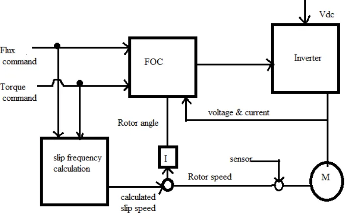
measured current components at their reference values. The pulse-width modulation of the variable-frequency drive describes the transistor switching according to the stator voltage references that are the output of the PI current controllers.FOC is used to manage the AC synchronous and induction motors. It was originally developed for high-performance motor applications that are required to operate smoothly over the bursting speed range, generate full torque at zero speed, and have high dynamic performance including fast acceleration and deceleration. However, it is becoming increasingly attractive for lower performance applications also due to FOC's motor size, cost and power consumption reduction dominance. It is expected that with increasing computational power of the microprocessors it will ultimately nearly universally relocate single-variable scalar volts-per-Hertz (V/f) control.
Fig 1. Field oriented control
III.FUZZY LOGIC CONTROLLER
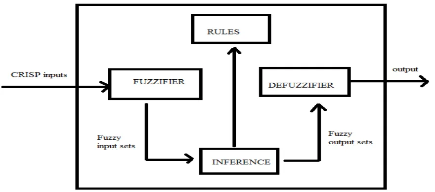
Fig 2 General block diagram of fuzzy logic controller
Table shows the rule base for controlling the speed
NL
NM NS ZE PS PM PLNL NL NL NLM NM NMS NS ZE
NM NL NLM NM NMS NS ZE PS
NS NLM NM NMS NS ZE PS PMS
ZE NM NMS NS ZE PS PMS PM
PS NMS NS ZE PS PMS PM PLM
PM NS ZE PS PMS PM PLM PL
PL ZE PS PMS PM PLM PL PL
IV.SYSTEM MODEL
The block model of the induction motor system with the controller be developed using the power system, power electronics, control system, signal processing toolboxes & from the fundamental functions available in the Simulink library in Matlab / Simulink. In this paper, plots of voltage, torque, speed, load & flux, etc are plotted as functions of time with the controller and the waveforms are observed on the equivalent scopes after running the simulations. The entire system modelled in Simulink is a closed loop feedback control system consisting of the plants, controllers, samplers, comparators, feedback systems, the mux, de-mux, summers, adders, gain blocks, multipliers, clocks, sub-systems, integrators, state-space models, subsub-systems, the output sinks (scopes), the input sources, etc. The developed simulink model for the control of various parameters of the SCIM is shown in the Fig 2.
ISSN (Print) : 2320 – 3765 ISSN (Online): 2278 – 8875
I
nternational
J
ournal of
A
dvanced
R
esearch in
E
lectrical,
E
lectronics and
I
nstrumentation
E
ngineering
(An ISO 3297: 2007 Certified Organization)
Vol. 4, Issue 4, April 2015
Fig 3 Vector control of induction motor
The inputs of a squirrel cage induction machine are the threephase voltages, their fundamental frequency, and the load torque. The outputs, on the other hand, are the three phase currents, the electrical torque, and the rotor speed.The d-q model requires that all the three-phase variables be transformed to the two -phase synchronously rotating frame Consequently, the induction machine model will have blocks transforming the three-phase voltages to the d-q frame and the d-q currents back to three-phase. Then the input is given to the IGBTThe insulated-gate bipolar transistor (IGBT) is a three-terminal power semiconductor device principally used as an electronic switch which, as it was developed, came to coalesce high efficiency and fast switching. It switches electric power in many up to date appliances: variable-frequency drives (VFDs), electric cars, trains, variable speed refrigerators, lamp weights, air-conditioners and even stereo systems with switching amplifiers. Since it is designed to turn on and off rapidly, amplifiers that use it frequently synthesize complex waveforms with pulse width modulation and low-pass filters. In switching applications modern devices feature pulse repetition rates well into the ultrasonic range— frequencies which are at least ten times the highest audio frequency knobbed by the device when used as an analog audio amplifier. The IGBT combines the simple gate-drive characteristics of MOSFETs with the high-current and low-dispersion-voltage capability of bipolar transistors. The IGBT combines an isolated gate FET for the control input, and a bipolar power transistor as a switch, in a particular device. The IGBT is used in medium- to high-power applications in the vein of switched-mode power supplies, traction motor control and induction heating. Large IGBT modules typically consist of many devices in parallel and can have very high current conduct capabilities in the order of hundreds of amperes with blocking voltages of 6000 V, associate to hundreds of kilowatts.
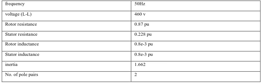
Ratings of induction motor used in the model:
frequency 50Hz
voltage (L-L) 460 v
Rotor resistance 0.87 pu
Stator resistance 0.228 pu
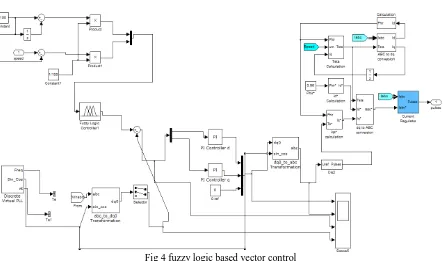
Fig 4 fuzzy logic based vector control
Any induction motor can be used to show the performance of the proposed speed controller. Fig. 4shows the simulation model of the vector control using fuzzy logic controller for an induction machine obtained using MATLAB optimization toolbox. The inputs of a squirrel cage induction machine are the threephase voltages, their fundamental frequency, and the load torque. The outputs, on the other hand, are the three phase currents, the electrical torque, and the rotor speed.The d-q model requires that all the three-phase variables be transformed to the two -phase synchronously rotating frame Consequently, the induction machine model will have blocks transforming the three-phase voltages to the d-q frame and the d-q currents back to three-three-phase.
V. RESULT AND DISCUSSION
A set of 49 fuzzy rules are written and called in the form of a file in the developed Simulink model with the controller. While the simulation is run, the 2 fuzzy inputs are then given to the controller (Takagi-Sugeno-fuzzy), where the output is obtained afterward. The response curves of flux, load, torque, terminal voltage, and speed & torques v/s time are observed on the respective scopes & are shown in the Figs. 3-4 respectively behind importing the scope data into the workspace and plotting them. From the simulation results shown in the Figs.6-7, it is observed that the stator current does not exhibit any overshoots, undershoots, the response of the flux, torque, terminal voltage, speed & stator
ISSN (Print) : 2320 – 3765 ISSN (Online): 2278 – 8875
I
nternational
J
ournal of
A
dvanced
R
esearch in
E
lectrical,
E
lectronics and
I
nstrumentation
E
ngineering
(An ISO 3297: 2007 Certified Organization)
Vol. 4, Issue 4, April 2015
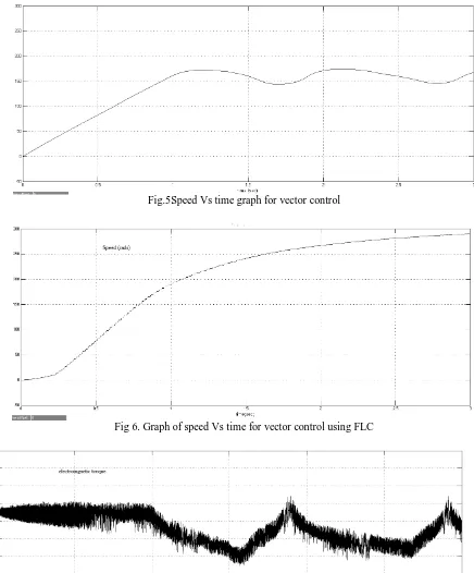
Fig.5Speed Vs time graph for vector control
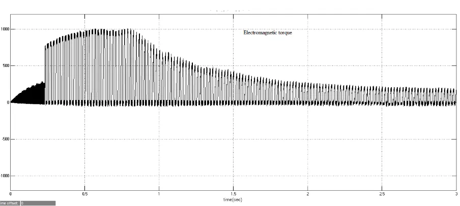
Fig 8 Torque Vs Time graph for vector control using fuzzy logic controller
Speed curve between set speed and time and torque of the induction motor has been shown. The curve compares the vector control and fuzzy based vector control of the induction motor. It can be observed that the settling time of the fuzzy based control less than that of the vector control. And torque is also less fluctuating in case of fuzzy based vector control.
VI.CONCLUSION
This paper presents some design approaches to hybrid control architectures combining conventional controltechniques with fuzzy logic and neural networks. Such hybrid structures lead to vigorous and easily tuned controllers, and are very well suited for systems with uncertain variations in plant parameters and structure. The induction motor is one of such intricate systemsand hence it can be considered as a challenging engineering problem for evaluating the performances of the designed controllers. The performance and robustness of the proposed controller have been evaluated under a variety of operating conditions of the drive system, and the results demonstrate the effectiveness of these control structures. A comparative study of the control strategies in terms of performance and robustness has been conducted. The performance is maintained under rotor resistance variations, which is known to cause performance deterioration invector-controlled induction motors. By using fuzzy logic controller with vector control considerably improved resultscompared with only conventional control are achieved. The control technique studied is very suitable for real time implementation due to their simplicity, robustness and ease ofregulation.
REFERENCES
[1]Simoes , M. G. , Bose , B. K. , Spiegel , R.J. “Design and performance evaluation of fuzzy logic based variable speed wind generation system”,IEEE Transactions on Industry Applications. Vol. 33 ,No. 4 , (July/august 1997), pp. 956-9d 65 .
[2] A. Gupta, “Simulation of Variable Speed Squirrel Cage Induction Motor ConstantVolts/Hertz Operation”, IEEE International on Electric Machines and Drives Conference Record, pp. TB3/8.1 -TB3/8.3, 1997.
[3] Jaime Fonseca, Joao L. Afonso, Julio S. Martins, Carlos Couto (1999), “Fuzzy logic speed control of an induction motor” ELSEVIER Microprocessors and Microsystems 22 (1999) 523-534, Department of Industrial Electronics, Minho University, Largo do paco, 4709-Braga Codex, Portugal.
[4] MouloudAzzedine DENAI, Sid Ahmed Attia (2002), “Fuzzy and neural control of an induction motor” AMCS journal paper, Vol.12, no.2,221- 233, University of Science and technology of Oran 31000.
[5]T,-J Ho and L.-Y Yeh (2003) “Design of a hybrid PID plus fuzzy controller for speed control of induction motors” Department of Electrical Engineering, Chung- Li, Taiwan.
[6] V. Chitra, and R. S. Prabhakar(2006), “Induction motor speed control using fuzzy logic controller” World academy of science, Engineering and Technology 23 2006.
ISSN (Print) : 2320 – 3765 ISSN (Online): 2278 – 8875
I
nternational
J
ournal of
A
dvanced
R
esearch in
E
lectrical,
E
lectronics and
I
nstrumentation
E
ngineering
(An ISO 3297: 2007 Certified Organization)
Vol. 4, Issue 4, April 2015
[8] AshokKasugar, Dr.S.F.Kodad, Dr. BV. SankarRam(2009), “Modelling of induction motor & control of speed using hybrid controller technology” Journal of theoretical and applied information technology (JATIT), www.jatit.org Research scholar, EEE Dept.,JNTU, Hydrabad-85, Andhra Pradesh, India.
[9] SedaAydemir, SerkanSezen, H. MetinErtunc (2009), “Fuzzy Logic spe control of a dc motor” Dept. of Electrical Engineering Kocaeli University, Izmit, Kocaeli, Turkey [email protected].
[10] D. Ben Attous and Y. Bekakra (2010), “Speed control of doubly fed induction motor using fuzzy logic techniques” International journal on Electrical Engineering and Informatics- Vol-2,No 3, 2010, Department of electrical engineering, EL-Oued University Centre. [email protected], [email protected].
[11] A. Abbou and H. Mahmoudi (2010), “Sensor less speed control of induction motor using DTFC based fuzzy logic” Journal of Electrical Engineering, www.jee.ro , L2EP, MohammadiaSchool’s of engineers Agdal Rabat Morocco.
[12] Ravi Maloth (2012), “Speed control of induction motor using fuzzy logic controller” National conference On Electrical Sciences-2012 (NCES- EEE Dept., KCEA, Nizamabad, ISBN:978-93-81583-72-2.
[13] DivyaRai, Swati Sharma, Vijay Bhuria (2012), “Fuzzy speed controller design of three phase induction motor” International Journal of emerging technology and advanced engineering (IJETAE), Vol 2, Issue 5, May 2012.
[14] Marwan A. Badran, Waleed F. Faris.(2013), “Fuzzy logic based speed control system for three phase induction motor”UEM paper, Analele Universita II “EFtimie MURGU” Resita Anul XX, NR.1, 2013, ISSN 1453-7397.