Enhancing Performance of Fuzzy controlled based
New Hybrid Unified Power Quality Conditioner
(HUPQC)
Ghousia M-tech EPS
Department of Electrical & Electronics Engineering, TKCcollege of Engineering &techology, medbowli;
meerpet (RR); Telangana, India. Email:[email protected]
S.Manohar reddy Assistant Professor
Department of Electrical & Electronics Engineering, TKCcollege of Engineering&techology , medbowli;
meerpet (RR); Telangana, India. Email:[email protected]
Abstract: With the widespread use of large-capacity power electronic devices, there are too much harmonic current and harmonic voltage in power system at the same time. The active power filter (APF) or hybrid active power filter (HAPF) can only eliminate harmonic current or harmonic voltage, and possibility resonance. To eliminate harmonic current and harmonic voltage in power system simultaneously and enhance the capacity, the concept presents a hybrid unified power quality conditioner (HUPQC). Compared with UPQC, the HUPQC is made up of a hybrid series active power filter (the series device) and a shunt active power filter (the shunt device). The shunt device employs an injection circuit to lower the capacity of the active part to fit high-voltage power system. Designed reasonably, and controlled with composite control method, the HUPQC can filter the harmonic current and harmonic voltage effectively at the same time. At the end of this concept, the simulation results improve that the HUPQC can prove the power quality greatly and achieve satisfactory effect.The proposed concept is further implemented to Fuzzy controlled concept using Matlab/Simulink software
Keywords— Power Quality, Hybrid Unified Power Quality Conditioner, Shunt Hybrid APF, DVR, DC-DC Converter
I INTRODUCTION
Evolution in characteristics of electrical loads as a result of developing technology and rapidly increasing electricity demand cause electrical power quality to become an important issue. The most common electrical power quality problems in electrical distribution systems are sags, swells, voltage and current harmonics. Due to the
inadequate performance of traditional
compensation devices, development of advanced technology power electronics based compensation devices is needed for compensation of these power quality problems. With the increasing power quality problems in distribution systems, unified power quality conditioner (UPQC), which is formed from shunt APF and DVR connected to common dc link, is developed. UPQC is an advanced compensation system that is used for compensation of power quality problems such as voltage sag swell, current-voltage harmonics, voltage ripple, voltage-current imbalances, voltage flicker and reactive power compensation [1-4]. In recent papers related with UPQC, various UPQC topologies have been proposed for different
purposes such as the multilevel UPQC [5] based on a three level neutral point clamped topology; the interline UPQC [6] where the series and shunt VSIs are connected to neigh boring feeders; the multi converter UPQC [7] in which three or more VSIs are applied to adjacent feeders similar to the interline UPQC; the modular UPQC [8,9] which is carried out by connecting several H-bridge VSI modules in cascade in each phase; the open UPQC [10,11] in which the series and shunt VSIs do not share a common dc link. In [12-14], UPQC topologies that include DC-DC converters in their DC links are suggested. In these studies DC-DC converters are used for charging energy storage devices in dc link of UPQC and in [15] are used for maintaining isolation between series and parallel inverters. In [16-19] hybrid UPQC topology formed from connection of DVR and SHAPF on common DC link is recommended.
In this paper, a new HUPQC topology is introduced that the dc link connection of shunt hybrid APF and DVR are realized by isolated bi-directional DC-DC converter. The rest of this paper is organized as follows: System description and power circuit topology of the proposed HUPQC is presented in Section 2. Control strategy is introduced in Section 3. Simulation results for different case studies are provided and discussed in Section 4. Conclusions of the study are given in Section 5.
II PROPOSED HUPQC SYSTEM:
formed from a three phase diode rectifier load which supplies an RC load with 3% line reactor. The sensitive load contains balanced RL loads that need purely sinusoidal voltages and must be fully protected against voltage distortions such as sag and swell. The system parameters of the proposed HUPQC are provided
III HUPQC CONTROL SYSTEM:
The HUPQC control system is based on Synchronous Reference Frame (SRF) where the DVR and SHAPF inverters are controlled independently. By using the SRF based controller, the fundamental component of load currents and source voltages are derived in order to obtain the reference current and voltage waveforms and thus to produce the switching signals properly.
A. SHAPF Controller:
The control scheme of the SHAPF is based on synchronous reference frame method which
presents easy implementation and low
computational cost. Functions of the SHAPF controller are to compensate for the harmonic components of nonlinear load current and to regulate the voltage of the dc link capacitor (Cdc2). The controller of SHAPF is mainly formed from harmonic current reference generation and current controller, dc link voltage controller and PWM controller as shown in Fig. 2.
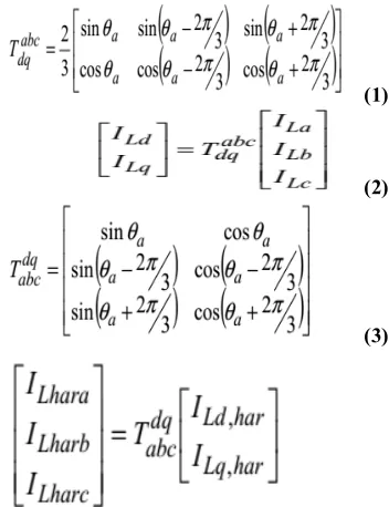
The harmonic compensation is performed by using direct current control strategy. The harmonic reference current is generated from load currents by using the SRF technique. The load currents (ILa, ILb, ILc) are firstly transformed in to dq domain (ILd, ILq) by using dq transformation and then passed
TABLE 1. SYSTEM PARAMETERS OF THE PROPOSED HUPQC
Fig.1.The structure of the proposed HUPQC system
Through a low pass filter (LPF) with cut of frequency of 10 Hz. The filtered components (ILdfil, ILqfil) are substracted from unfiltered components (ILd, ILq) to obtain harmonic current references in dq domain (ILd,har, ILq,har). In order to generate the harmonic references in three phase coordinates (ILa,har, ILb,har,ILc,har), the inverse dq transformation is applied. The dq
transformation matrix and the inverse
transformation matix are given in Eq. (1),(2) and (3),(4) respectively.
(1)
(2)
(3)
(4)
In a similar way, the current harmonics of the
SHAPF in three phase coordinate (IFa,har,
SHAPF side DC link voltage (Vdc2) is subtracted from the reference value (Vdc2ref) and the resulting error signal (Vdc2err) is applied to PI controller. The DC link voltage controller reference signal (Vdcref) for each phases are obtained by using the inverse dq transformation matrix where the output of PI controller is the input of q component.
Finally, the three phase reference voltage signals (Varef, Vbref, Vcref) are generated by adding up the harmonic voltage error signals and DC link voltage controller reference signals.
Fig.2. Block diagram of control algorithm for SHAPF
B. DVR Controller:
The controller of DVR is designed to control each
phase independently that performs voltage
measurements (Vs and Vl), sag/swell detection, reference voltage extraction and gate signal generation as it is presented in Fig.3.
In the proposed controller of DVR, three phase bus bar voltages (vsa, vsb, vsc) are measured and then the “per unit” transform is applied. The magnitude information “A(t)” is determined with the improved SRF based controller for each phase independently by using the per unit values of bus bar voltages and
phase angles ș(t) obtained with EPLL. The
improved SRF technique can be applied to realize the reference voltage when the unbalanced voltage sag/swell occurs unlike the conventional SRF. In the conventional SRF technique, the three phase voltage signals are used and an average magnitude value is produced as a result of calculated average values of d- and q- components for three phase. For this reason, the conventional SRF technique is not
preferred in unbalanced voltage sag/swell
conditions. On the other hand, the improved SRF technique produce the magnitude values separately for each phase as follows;
(5)
(6)
(7)
Fig.3 presents the d-q transformation for each phase by using the measured actual voltage value and the reference voltage values created virtually. The generation of reference values of two other phase are provided in Eq. (8), (9) and (10) by using the measured voltage information.
(8)
(9)
(10)
The voltage sag/swell depth “Sdepth” can be found by subtracting the magnitude information from 1 pu value which should be in nominal conditon. When a sag or swell occurs, the “Sdepth” can be detected higher than the limit value of 10% (0.1 pu) and gives voltage sag/swell detection signal as a result of hysteresis comparator. The voltage sag/swell detection signal enables the PWM for each phase to produce switching signal with respect to the reference voltage.
measured capacitor current, and the result is multiplied by the current gain (kc) to form the feedback voltage.
Fig.3. The improved SRF technique
Fig.4. the structure of DVR control
C. DC-DC Converter Controller:
The isolated bi-directional controller is based on a single phase shift (SPS) method that the power transfer between DVR and SHAPF can be easily controlled by adjusting phase shift between the primary and secondary side voltages (v1 and v2) of the high frequency transformer. The phase shift
angle (į) between the square voltages v1 and v2 are determined by using PI controller.
IVINTRODUCTIONTOFUZZYLOGIC
CONTROLLER
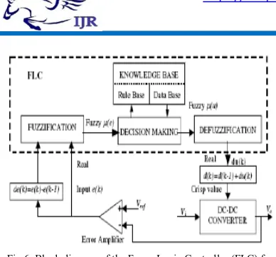
L. A. Zadeh presented the first paper on fuzzy set theory in 1965. Since then, a new language was developed to describe the fuzzy properties of reality, which are very difficult and sometime even impossible to be described using conventional methods. Fuzzy set theory has been widely used in the control area with some application to dc-to-dc converter system. A simple fuzzy logic control is built up by a group of rules based on the human knowledge of system behaviour. Matlab/Simulink simulation model is built to study the dynamic behaviour of dc-to-dc converter and performance of proposed controllers. Furthermore, design of fuzzy logic controller can provide desirable both small signal and large signal dynamic performance at same time, which is not possible with linear control technique. Thus, fuzzy logic controller has been potential ability to improve the robustness of dc-to-dc converters. The basic scheme of a fuzzy logic controller is shown in Fig 5 and consists of four principal components such as: a fuzzification interface, which converts input data into suitable linguistic values; a knowledge base, which consists of a data base with the necessary linguistic definitions and the control rule set; a decision-making logic which, simulating a human decision process, infer the fuzzy control action from the knowledge of the control rules and linguistic variable definitions; a de-fuzzification interface which yields non fuzzy control action from an inferred fuzzy control action [10].
Fig.5. General Structure of the fuzzy logic controller on closed-loop system
The fuzzy control systems are based on expert knowledge that converts the human linguistic concepts into an automatic control strategy without
any complicated mathematical model [10].
Fig.6. Block diagram of the Fuzzy Logic Controller (FLC) for dc-dc converters
A. Fuzzy Logic Membership Functions:
The dc-dc converter is a nonlinear function of the duty cycle because of the small signal model and its control method was applied to the control of boost converters. Fuzzy controllers do not require an exact mathematical model. Instead, they are designed based on general knowledge of the plant. Fuzzy controllers are designed to adapt to varying operating points. Fuzzy Logic Controller is designed to control the output of boost dc-dc converter using Mamdani style fuzzy inference system. Two input variables, error (e) and change of error (de) are used in this fuzzy logic system. The single output variable (u) is duty cycle of PWM output.
Fig. 7.The Membership Function plots of error
Fig.8. The Membership Function plots of change error
Fig.9. the Membership Function plots of duty ratio
B. Fuzzy Logic Rules:
The objective of this dissertation is to control the output voltage of the boost converter. The error and change of error of the output voltage will be the inputs of fuzzy logic controller. These 2 inputs are divided into five groups; NB: Negative Big, NS: Negative Small, ZO: Zero Area, PS: Positive small and PB: Positive Big and its parameter [10]. These fuzzy control rules for error and change of error can be referred in the table that is shown in Table II as per below:
Table II
Table rules for error and change of error
V MATLAB/SIMULATION RESULTS:
Fig 10 Simulation model for HUPQC system
Fig 11 Simulation waveform for Harmonic compensation performance of the SHAPF
Fig 13 Simulation waveform for dc link voltages
Fig 14 Simulation waveform for load voltages of DVR sag/swell compensation with fuzzy logic controller
Fig 15 Simulation waveform for dc link voltages with fuzzy logic controller
VI CONCLUSION
In this paper, a new HUPQC topology is as an alternative solution to electrical power quality problems in distribution systems. In HUPQC, dc link connection of shunt hybrid APF and DVR are realized by isolated bidirectional DC-DC converter. The preferred DVR topology in the proposed HUPQC enables the compensation of unbalanced voltage sag and swells for the first time in literature within hybrid UPQC concept. The preferred shunt hybrid APF topology enables the reduction in the voltage rating of DC link capacitor and helps to reduce the cost and size of DC link and APF inverter. The dynamic response and performance of the DVR is improved with the DC-DC converter by keeping the DVR side DC link voltage stable during voltage sags and swells. DC-DC converter also provides isolation between DVR and hybrid APF inverters.
REFERENCES:
[1] Ghosh A., Ledwich G., 2002. “Power Quality Enhancement Using Power Devices”.
[2] Akagi H., 2005. “Active Harmonic Filters” Proceedings of the IEEE, 93 (12): 2128.
[3] Fujita H., Akagi H., 1996. “The Unified Power Quality Conditioner: The Integration of Series Active Filters and Shunt Active Filters”, Power
Electronics Specialists Conference, Page(s): 494-501.
[4] Khadkikar V., 2012. “Enhancing electric power quality using UPQC: A Comprehensive Overview”, IEEE Transactions on Power Electronics, 27 (5): 2284-2297.
[5] Rubilar I., Espinoza J., Munoz J., Moran L., 2007. “DC link voltage unbalance control in three-phase UPQCs based on NPC topologies,” in Proc. 42nd Industrial Application Annual Meeting, Page(s): 597–602.
[6] Jindal A.K., Ghosh A., Joshi A., 2007. “Interline uni¿ed power quality conditioner,” IEEE Transactions on Power Delivery, 22 (1): 364 372. [7] Mohammadi H.R., Varjani R.Y., Mokhtari H.,
2009. “Multiconverter uni¿ed power-quality
conditioning system: MC-UPQC,” IEEE
Transactions on Power Delivery, 24 (3):1679– 1686.
[8] Han B., Bae B., Baek S., Jang G., 2006. “New con¿guration of UPQC for medium-voltage
application,” IEEE Transactions on Power
Delivery, 21 (3):1438–1444.
[9] Munoz J.A., Espinoza J.R., Moran L.A., Baier C.R., 2009. “Design of a Modular UPQC
Configuration Integrating a Components
Economical Analysis” IEEE Transactions on Power Delivery, 24 (4): 1763–1772.
[10] Brenna M., Faranda R., Tironi E, 2009. “A New Proposal for Power Quality and CustomPower Improvement: OPEN UPQC” IEEE Transactions on Power Delivery, 24 (4): 2107-2116.
[11] Teke A., Meral M.E., Cuma M.U., Tumay M., Bayindir K.C., 2013. “OPEN unified power quality conditioner with control based on enhanced phase locked loop” IET Generation, Transmission & Distribution, 7 (3): 254-264.
[12] Han B., Cho B., Sul S., Kim J., 2006. ”Unified Power Quality Conditioner for Compensating Voltage Interruption”, Journal of Electrical Engineering & Technology, 1 (4): 503-512. [13] Siahi M., Hoseynpoor M., Najafi M., Ebrahimi R., 2011. “Design and Simulation of UPQC with Super-Capacitor to Energy Storage and Improve Power Quality , Australian Journal of Basic and Applied Sciences, 5 (3):674-681.
[14] Davari M., Ale-Emran S.M., Yazdanpanahi H., Gharehpetian G.B., 2009. “Modeling the Combination of UPQC and Photovoltaic Arrays
with Multi-Input Single-Output DC-DC
Converter”, IEEE/PES Power Systems Conference and Exposition, Page(s): 1-7.
[15] Yang Zhang, Shengfa Zhang, Jiahong Chen, 2008. “The Applications of Bidirectional Full-bridge DC-DC Isolated Converter in UPQC”, International Conference on Electrical Machines and Systems, Pages:1916-1921.
Conditioner”, Power Engineering Society Winter Meeting, Page(s): 2594 - 2599.
[17] Zhou L. H., Fu Q., Liu C., 2009. “Modeling and Control Analysis of a Hybrid Unified Power Quality Conditioner”, Asia-Pacific Power and Energy Engineering Conference, Page(s): 1-5. [18] Karanki S., Geddada N., Mishra M., Boddeti K., 2012. “A Modi¿ed Three-phase Four Wire UPQC Topology with Reduced DC-link Voltage
Rating”, IEEE Transactions on Industrial
Electronics.
[19] Hailian Z., Jianru W., Chenhu Y., Shuchao L., 2011. “Analytical Research on Unified Power Quality Conditioner Based on Super Capacitors
Energy Storage System”, 4th International