Fuzzy based Grid voltage Synchronization for
Distributed Generated System
G.Chandra
Assitantant Professor
Department of Electrical & Electronics Engineering, Anurag college of engineering,Avushapur(v) Ghatkesar(M);
Rangareddy (Dt); Telangana, India. Email:[email protected]
Bangaroju Somayyachary
M-tech Student Scholar
Department of Electrical & Electronics Engineering, Anurag college of engineering,Avushapur(v) Ghatkesar(m);
Rangareddy (Dt); Telangana, India. Email:[email protected]
Abstract:In this project behavior of advanced grid synchronization systems and structures are presented. The transmission system operators (TSOs) are especially concerned about the low-voltage-ride-through requirements. Solutions based on the installation of STATCOMs and dynamic voltage regulators (DVRs), as well as on advanced control functionalities for the existing power converters of distributed generation plants, have contributed to enhance their response under faulty and distorted scenarios and, hence, to fulfill these requirements. In order to achieve satisfactory results with such systems, it is necessary to count on accurate and fast grid voltage synchronization algorithms, which are able to work under unbalanced and distorted conditions. This project analyzes the synchronization capability of three advanced synchronization systems: the decoupled double synchronous reference frame phase-locked loop (PLL), the dual second order generalized integrator PLL, and the three-phase enhanced PLL, designed to work under such conditions. Although other systems based on frequency-locked loops have also been developed, PLLs have been chosen due to their link with dq0 controllers. The proposed concept is implemented to Fuzzy logic controller by using mat lab/simulink software.
Index Terms—Distributed Generated (DG) System, Grid Synchronization, Micro grid, series compensation controller.
I INTRODUCTION
A micro grid is a part of distribution network thatincludes multiple loads and distributed energy resourceconverters that are operated in parallel with the boarderutility grid [1]. It helps in integration of distributedenergy resource converters to micro grid. Micro grid is a partof distributed generation system. It is a localized groupingof electricity generation, energy storage and loads thatnormally operates connected to a traditional centralizedutility grid. The component of micro grid involvesdistributed generation resources such as photovoltaicpanels, small wind turbines, fuel cells, etc.
The storage devices are batteries, super capacitors,flywheeletc along with local loads. Better efficiency,superior quality with high reliability of power supplyhaving environmental as well as economical benefits can beachieved by using microgrid [2]. A droop control is a controltechnique applied to distributed generation system forprimary frequency control and as well as voltage controlfor load sharing between local loads to utility Grid.By controlling the frequency, as well as voltage,corresponding active
power (P) and reactive power (Q) canbe controlled in distributed generation. Increase in activepower output results in reduction of frequency and thecorresponding increase in the reactive power results indecrease of voltage as explained in [3].
The concept of Phase Locked Loop (PLL) is used for theimplementation of grid synchronization method. PLL isused for the estimation of grid voltage, phase angle andfrequency. A PLL is a control system in which outputsignal is generated by relating its phase to the phase of aninput signal. A PLL can track an input frequency or it cangenerate a frequency that is a multiple of the inputfrequency as explained in [4]-[7].
This paper a series compensation controller basedsynchronization method is proposed for achieving the gridsynchronization in terms of frequency, phase angle,amplitude of output voltages, active power and reactivepower in between converter output and Distributed EnergyResource Converters (DERCs). The series compensationcontrolleris replaced by proportional integral (PI) controller forobtaining fast dynamic response, low steady error and for stable operation [8].
Fig.1.Block Diagram of PLL Controller
The concept on series compensation set theory was introduced by
L. A. Zadeh in 1965.Series compensation is rule based and it isapplication of human knowledge on system behavior as explained in. Fig.2 represents the schematicdiagram of series compensation based system.
Fig 2: Schematic of Series compensation based system Series compensation controller operation mainly involves the execution of four major operations:
Fuzzification
Rule based Inference system
Composition and Defuzzification
Fuzzification involves the conversion of crisp values or classical set values toSeries compensation rule base values. It involves the choice of Variables, series compensation Input and output variables and the evaluation of membership functions. It involves series compensation subset rules, composition and defuzzification. For assigning each series compensation subset rule based value to the output variable a Rule based series compensationinference system is necessary. Composition helps in forming a Single series compensation subset rule based Value assigned to an output variable from a multiple rule based series compensation subset values. Defuzzification helps in the conversion of composition of series compensation rule based value to a single crisp value [11-12].
Defuzzification helps in the conversion of composition of series compensation rule based value to a single crisp value. A PI controller is replaced with a series compensation controller is as shown in fig.3.
Fig 3: Block diagram of series compensation controller The main objective of designing the Series compensation logic rules is to synchronize the grid parameters such as grid frequency, phase angle, amplitude of output voltages, active power and reactive power with the output of the distributed energy resource
converters. The error and change of error are the inputs of the series compensationcontroller.
II GRID SYNCHRONIZATION ECIFICATIONS BASED ON GCR
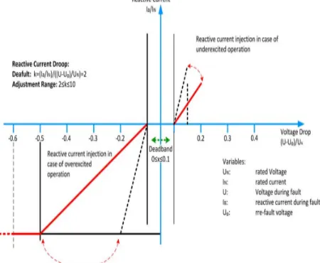
Even though several works are published within the field ofgrid synchronization, almost all of them are centered on analyzing the individual dynamic performance of each proposal,without first determining a time response window within thedynamic behavior of the system under test, which would beconsidered to be satisfactory.In this paper, in order to evaluate the response of the gridsynchronization topologies under test, a common performancerequirement for all the structures has been established in thissection, considering the needs that can be derived from theLVRTrequirements.Despite the fact that the detection of the fault can be carriedout with simpler algorithms, as shown in and, theimportance of advanced grid synchronization systems lies in thenecessity of having accurate information about the magnitudeand phase of the grid voltage during the fault, in order to injectthe reactive power required by the TSO.In the German standard [2], it is stated that voltage controlmust take place within 20 ms after the fault recognition, byproviding a reactive current on the low voltage side of thegenerator transformer to at least 2% of the rated current for eachpercent of the voltage dip, as shown in Fig.4. 100% reactivepower delivery must be possible, if necessary.
Fig.5. REE voltage support requirement in the event of grid fault. A similar condition is given in the Spanish grid code, wherethe wind power plants are required to stop drawing inductivereactive power within 100 ms of a voltage drop and be able toinject full reactive power after 150 ms, as shown in Fig.5.
Considering these demands, this paper will consider that theestimation of the voltage conditions will be carried out within20–25 ms, as this target permits it to fulfill the most restrictiverequirements, in terms of dynamical response, available inthe grid codes. This condition will be extended to frequencyestimation; although this parameter is more related to secondarycontrol algorithms than LVRT, the same time window between20 and 25 ms will be considered in this work for the detectionof the disturbance.
III DESCRIPTION OF THE THREE
SYNCHRONIZATION SYSTEMS
Many of the positive-sequence detection algorithms arebased on SRF PLLs. Despite having a good response underbalanced conditions, their performance becomes insufficient inunbalanced faulty grids (95% of cases), and their good operation is highly conditioned to the frequency stability, which isincompatible with the idea of a robust synchronization system.
Fig.6. DDSRF-PLL block diagram.
Many authors have discussed different advanced models, whichare able to overcome the problems of the classical PLL, usingfrequency and amplitude adaptive structures which are able todeal with unbalanced, faulty, and harmonic-polluted grids. Inthe framework of these topologies, three PLL structures will bediscussed and evaluated in this paper. A) DDSRF PLL
The DDSRF PLL published in and was developedfor improving the conventional SRF PLL. This synchronizationsystem exploits two synchronous reference frames rotating atthe fundamental utility frequency, one counterclockwise andanother one clockwise, in order to achieve an accurate detectionof the positive- and negative-sequence components of the gridvoltage vector when it is affected by unbalanced grid faults. Thediagram of the DDSRF PLL is shown in Fig.6.
When the three-phase grid voltage is unbalanced, the fundamental positive-sequence voltage vector appears as a dc voltageon the dq+1 axes of the positive-sequence SRF and as acvoltages at twice the fundamental utility frequency on the dq−1axes of the negative-sequence SRF. In contrast, the negativesequence voltage vector will cause a dc component on thenegative-sequence SRF and an ac oscillation on the positivesequence SRF. Since the amplitude of the oscillation on thepositive-sequence SRF matches the dc level on the negativesequence SRF and vice versa, a decoupling network is appliedto signals on the dq positive/negative SRF axes in order tocancel out such ac oscillations. Low-pass filters (LPFs) inFig.6are responsible for extracting the dc component fromthe signal on the decoupled SRF axes. These dc componentscollect information about the amplitude and phase angle of thepositive- and negative-sequence components of the grid voltagevector.
Finally, the PI controller of the DDSRF PLL works on thedecoupled q-axis signal of the positive-sequence SRF (v∗q+1)and performs the same function as in an SRF PLL, aligning thepositive-sequence voltage with the d-axis. This signal is free ofac components due to the effect of the decoupling networks; thebandwidth of the loop controller can be consequently increased.
B) DSOGI PLL
Fig.7. DSOGI-PLL block diagram.
To apply the ISC method, it is necessary to have a set ofsignals, vα–vβ, representing the input voltage vector on the αβstationary reference frame together with another set of signals, qvα–qvβ, which are in quadrature and lagged with respecttovα–vβ. In the DSOGI PLL, the signals to be supplied tothe ISC method are obtained by using a dual second ordergeneralized integrator (DSOGI), which is an adaptive bandpass filter based on the generalized integrator concept.At its output, the DSOGI provides four signals, namely, vα and vβ, which are filtered versions of vα and vβ, respectively, and qvα andqvβ, which are the in-quadrature versionsofvα and vβ.
A conventional SRF PLL is applied on the estimatedpositive-sequence voltage vector, vαβ +, to make this synchronization system frequency adaptive. In particular, the vαβ + voltage vector is translated to the rotating SRF, and the signal ontheq-axis, v+q, is applied at the input of the loop controller.As a consequence, the fundamental grid frequency (ω) and the phase angle of the positive-sequence voltage vector (θ+) are estimated by this loop. The estimated frequency for thefundamental grid component is fed back to adapt the centerfrequencyω of the DSOGI. C) 3phEPLL
The enhanced phase-locked loop (EPLL) is a synchronization system that has proven to provide good results in singlephase synchronization systems. An EPLL is essentiallyan adaptive bandpass filter, which is able to adjust the cut off frequency as a function of the input signal. Its structure waslater adapted for the three-phase case, in order to detectthe positive-sequence vector of three-phase signals, obtainingthe 3phEPLL that is represented in Fig.8.
In this case, each phase voltage is processed independentlyby an EPLL. This block filters the input signal and generatestwo sinusoidal outputs of the same amplitude and frequency,vnandjvn, the second one being 90◦ with respect to vn.The resulting signals constitute the input for the computationalunit. Owing to these in-quadrature signals, the instantaneouspositive-sequence voltage component, vabc+, can be estimatedby means of using the ISC method.
IV DISCRETE IMPLEMENTATION
The performance of the different structures under test is reallydependent on their final digital implementation,
particularly onthe discretization approach made to their continuous equations.
Fig.8. 3phEPLL block diagram.
Fig.9.Phase and magnitude estimation loop of the DDSRF PLL.
This implementation is critical and should be studied indetail as a straightforward implementation can give rise to additional delays in the loop that hinder the good performance of thePLL. Some methods, such as the forward Euler, the backwardEuler, and the Tustin (trapezoidal) numerical integration, off area good performance when used for discrediting other synchronization systems. However, Eulermethods can be inadequate under certain conditions, due to theneed of introducing additional sample delays. Therefore,according to the specific needs of the presented topologies, thissection will describe the discrete representation of each PLLindividually. In order to facilitate the comprehension of theprocess, the different building blocks that appear at Figs. 6–8 will be referenced.
A) DDSRF-PLL Discretization
The discrete model of this PLL can be easily obtained sincethe continuous representation of several parts does not changein the discrete domain. This is the case for the transformationblocks Tαβ, Tdq+1, and Tdq−1, whose description can be found,in general, scope literature.
same as in the continuous domain. It is just necessary to consider one sample delay of θ, v ¯d−1, v ¯q−1, v ¯d+1, and v ¯q+1 in order to avoid algebraic loops.
2) Phase and Magnitude Estimator Discretization: In the DDSRF PLL, the decoupling network appears embedded in the classical SRF-PLL loop (see Fig. 9). However, thisdoes not affect the discretization of the phase and magnitude estimator since v∗d+1 and vq∗+1 act as the input of this block
(1) The discrete controller and the integrator can be built using abackward numerical approximation. The frequency and phasecan then be represented in the z-domain (2), considering v∗q+1as the error to be minimized. In this equation, a feedforwardofthe nominal frequency is given by means of ωff.
(2) Finally, sample-based representation gives rise tohare the expressions to be implemented
(3) In these equations, a frequency feedforward has been introduced as an initial condition to ω’.
3) LPF Block Discretization: The amplitudes of the dq positive- and negative-sequence components are the outputs of the decoupling networks. However, four infinite impulse responses (IIR) LPFs extract the ripple from each sequence estimation in order to reinforce the performance of the PLL in case of harmonic pollution. A first-order filter with a cutoff frequency ωf , equal to half of the grid frequency, was originally proposed in; hence, the same transfer function has been implemented in this paper for evaluation purposes in
(4)
B) DSOGI-PLL Discretization
1) DSOGI-QSG Block Discretization: Aswas previously mentioned, the DSOGI-based quadrature signal generator (QSG) of Fig.10 consists of two independentand decoupled second-order generalized integrators (SOGIs).Therefore;each SOGI-based quadrature signal generator canbediscredited individually, thus facilitating it’sathematical description. In Fig.10, the block diagram of the implementedSOGI is shown.
Fig.10. Quadrature signal generator based on a second order generalizedintegrator (SOGI QSG).
This quadrature signal generator (QSG) is a linear systemitself; therefore, a discrete representation can be systematicallyobtained if the continuous state space is previously deducted.The equations of the SOGI state space appear detailed in (5).where v constitutes the input while v and qv are the two inquadrature output signals
(5)
(6) The discretization of this system has been performed usingtrapezoidal integrators, as they offer a better detection of thephase, which is important when dealing with sinusoidal signal. The symbolic values of each matrix of (7) are detailed in (6), shown at the bottom of the page. In these matrices, Tsisthe sampling time of the
estimatedfrequencymagnitude, which comes from the estimation madeat the SRF-PLL block at each computation step, and k is theSOGI gain
(7) The discrete state space of (6) is obtained from the continuous representation by means of the mathematical procedure
(8)
Fig.11. State variables of the SRF-PLL block.
WhereTs is the sampling time.The resulting discrete system is the best option as it reducesthe need of using additional delays for breaking algebraic loopsthat appear using other methods which do not consider theSOGI QSG as a whole.
2) SRF PLL Discretization: The frequency and phase detection is obtained by means of the SRF PLL shown in Fig.11. Thediscretization of the controller and the integrator is performedusing the backward numerical approximation.The frequency and phase can then be represented in thez-domain, as shown in (9), where v+q constitutes the error tobe minimized
(9)
It can be noticed that the previous equations in (9) are equalto (2), as, in both cases, an SRF PLL is implemented. Likewise, the sample-based representation of (9) can be written asshown in
(10) This three-phase grid synchronization system exploits theEPLL as a quadrature signal generator. An independent EPLLis used for processing each one of the three-phase voltages. Thesame EPLL structure is applied again to detect the magnitudeand phase of the positive-sequence voltage component.
1) QSG Block—EPLL Discretization: The block diagram of the EPLL implemented in this paper is presented in Fig.12.
Fig.12. Quadrature signal generator based on an EPLL structure
According to this diagram, the state space representation ofthe EPLL in the continuous domain can be written as shown in
(11) The discrete state space variable representation using a forward Euler approximation to rechastisefactory results; therefore, the same method has been implemented here
Finally, after the state variables are calculated, the EPLL output can be obtained by (13), generating the two quadraturesignals
(13) This type of discretization method needs a more accuratetuning, due to the fact that the stable regions of the s-planeand z-plane are different. However, its major simplicity,compared to the Tustin or backward integration, benefits fromthe computational speed of this block.
2) Computational Block Unit: The description for this blockis the same in both discrete and continuous domains. Nevertheless, specific equations are used in this paper, as shown in (14).
3) Phase and Magnitude Detection Block: This element isbased on another EPLL, which is responsible for estimating the phase and the magnitude of the Positive-sequence
fundamentalcomponent.Itsdiscretization is equal to that shown in (12).
(14) V SERIES COMPENSATION
WITH FUZZYLOGICCONTROLLER
Series Compensation Method A dynamic voltage restorer (DVR) was introduced for mitigating a voltage sag. The DVR is based on an Voltage source converter (VSC) system that has energy storage for supplying active power, an output filter to make output voltage wave sinusoidal, and a step up transformer connected in series with line.
A DVR is configured as a series-connected voltage controller. To control the output voltage of the DVR, the inverter supplies the missing load voltage using self-commutable electronic switches such as a gate turn-off thyristor (GTO), or an insulated gate bipolar transistor (IGBT), or an insulated gate commutated thyristor (IGCT). A DVR injects the missing voltage in series; it can be called a series voltage controller, but the term DVR is commonly used now. The advantages of the DVR are fast response, ability to compensate for voltage sag and a voltage phase shift using an inverter system. Three schemes can be used to generate the missing voltage in series with the source voltage for compensating the voltage sag such as,
In-phase voltage injection
Phase-invariant voltage injection
Phase advanced voltage injection
In the in-phase voltage injection scheme,
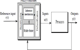
General structure of the fuzzy logic controller on closed-loop system
The fuzzy control systems are based on expert knowledge that converts the human linguistic concepts into an automatic control strategy without any complicated mathematical model [10]. Simulation is performed in buck converter to verify the proposed fuzzy logic controllers.
Block diagram of the Fuzzy Logic Controller (FLC) for dc-dc converters
A. Fuzzy Logic Membership Functions:
The dc-dc converter is a nonlinear function of the duty cycle because of the small signal model and its control method was applied to the control of boost converters. Fuzzy controllers do not require an exact mathematical model. Instead, they are designed based on general knowledge of the plant. Fuzzy controllers are designed to adapt to varying operating points. Fuzzy Logic Controller is designed to control the output of boost dc-dc converter using Mamdani style fuzzy inference system. Two input variables, error (e) and change of error (de) are used in this fuzzy logic system. The single output variable (u) is duty cycle of PWM output.
The Membership Function plots of error
The Membership Function plots of change error
The Membership Function plots of duty ratio
B. Fuzzy Logic Rules:
The objective of this dissertation is to control the output voltage of the boost converter. The error and change of error of the output voltage will be the inputs of fuzzy logic controller. These 2 inputs are divided into five groups; NB: Negative Big, NS: Negative Small, ZO: Zero Area, PS: Positive small and PB: Positive Big and its parameter [10]. These fuzzy control rules for error and change of error can be referred in the table that is shown in Table II as per below:
Table II
Table rules for error and change of error
VI MATLAB/SIMULATION RESULTS
Fig 14.simulation wave form DDSRF harmonic, frequency, LLLG and unbalance condition
Fig 15 Matlab/simulation circuit of dual second order generalized integrator PLL
Fig 17 Matlab/simulation circuit of three-phase enhanced PLL (3phEPLL)
Fig 18 simulation wave form of (3phEPLL) Harmonic, frequency, LLLG and unbalance condition
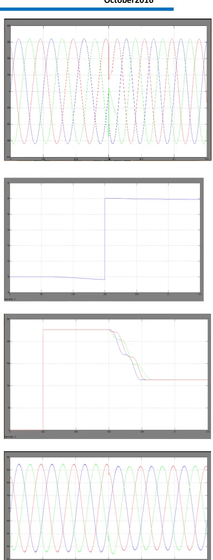
Fig 19 Matlab/simulation circuit of series compensation with fuzzy logic controller
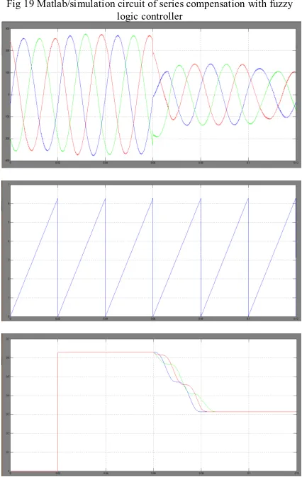
Fig 20 simulation wave form of series compensation with fuzzy logic Harmonic, frequency, LLLG and unbalance condition
VI CONCLUSION
The DDSRF PLL and the DSOGI PLL allow estimating the ISCs of a three-phase system working in the αβ reference frame, while the 3phEPLL uses the “abc” reference frame, thus working with three variables. As has been shown, this feature simplifies the structure of the DSOGI PLL and the DDSRF PLL, which allows reducing the computational burden, as compared to the 3phEPLL, without affecting its performance.
REFERENCES
[1] A. Zervos and C. Kjaer, Pure Power: Wind Energy Scenarios for 2030. Brussels, Belgium: European Wind Energy Association (EWEA),Apr. 2008. [Online]. Available: http://www.ewea.org/index.php?id=11
[2] e-on, “Grid code—High and extra high voltage,” Bayreuth, Germany. Apr. 2006. [Online]. Available:
http://www.pvupscale.org/IMG/pdf/
D4_2_DE_annex_A-3_EON_HV_grid__connection_requirements_ENENARHS20 06de.pdf[3] M. Molinas, J. A. Suul, and T. Undeland, “Low voltage ride through of wind farms with cage generators: STATCOM versus SVC,”IEEE Trans. Power Electron., vol. 23, no. 3, pp. 1104–1117, May 2008. [4] K. Li, J. Liu, Z. Wang, and B. Wei, “Strategies and operating pointoptimization of STATCOM control for voltage unbalance mitigation in three-phase three-wire systems,” IEEE Trans. Power Del., vol. 22, no. 1, pp. 413–422, Jan. 2007.
[5] J. A. Barrena, L. Marroyo, M. A. R. Vidal, and J. R. T. Apraiz, “Individual voltage balancing strategy for PWM cascaded H-bridge converterbased STATCOM,”IEEE Trans. Ind. Electron., vol. 55, no. 1, pp. 21–29,Jan. 2008
[6] R.Lasseter, ―Microgridsǁ, in Proc.IEEE Power Eng.soc.winter meeting, 2002, pp. 305-308.
[7] Micro grid, a conceptual solution by R.H.Lasseter, Paolo Piagi University of Winsconsin-Madison,Winsconsin. [8] Modeling,control and fault management of micro grids by Mehdi Moradian, Faramarz.
[9] Autonomous control of micro grids by Paolo Piagi member, IEEE,Robert H Lasseter, Fellow,IEEE.
[10] Droop control based power sharing for a micro grid with manifold Distributed Generations by Km Shobana, N Chitra.
[11] Phase locked loop control of Inverters in a micro grid by Matthevosupernant, IanHiskens and GiriVenkataraman. [12] Y.A.I.Mohamed and A.A.Radwan, ―Hierarchial control system for robust micro grid operation and seamless mode transfer in active distribution systemsǁ, IEEE Trans. Smart Grid, vol.2, no. 2, pp. 352–362, Jun. 2011.
Author’s profile:
Bangarojusomayyachary Received B.E in Electrical and Electronics Engineering From Vathsalyainstuite of science&tech in 2014,He is Currently Pursuing M.Tech (Electrical power
systems) From Anuragcollegeof engineering ,Avushapur(v),Ghatkesar(m)R.R DIST,Telangana.