POWER FACTOR CORRECTION CONTROLLER FOR
PMBLDC MOTOR USING DUAL BOOST CONVERTER
Mrs.Sindhuja.G
1, Dr.Shankar.C.B
2and Dr.R.Prakash
31
Student Member IEEE,
2,3Professor
Dept. of Electrical and Electronic Engineering,
Visvesvarya Technological University, Bangalore-560090, (India)
ABSTRACT
In this paper, a circuit for power factor correction by implementing two boost converters arranged in parallel is
developed. The simulation of conventional rectifier circuit is carried out without power factor correction controller
and analysis of input current waveform is done. Simulation is performed with gradual increase in complexity by
inclusion of boost and dual boost topology. Considerable reduction in Total Harmonic Distortion (THD) is observed
with dual boost converter topology. Simulation work is performed using MATLAB / SIMULINK environment.
Ke words: Boost converter, PFC, PMBLDCM, PI controller, THD
I INTRODUCTION
Brush Less DC (BLDC) motors are widely used in industries such as appliances, consumer, automotive, medical, aerospace, industrial automation Equipment and Instrumentation. Permanent Magnet Brush Less (PMBL) motors belong to three-phase synchronous motor family and can be categorized as Permanent Magnet Synchronous Motor (PMSM) and PMBLDCM. The PMSM uses continuous rotor position feedback for supplying sinusoidal voltages and currents to the motor with sinusoidal back EMF, so that the interaction with sinusoidal currents produces constant torque with very low ripple. PMBL machines are best suited for position control and medium size industrial drive because of their excellent dynamic capability, reduced losses and high torque and weight ratio. [5]
Various Power Factor Correction (PFC) techniques are employed to overcome power quality problems out of which the boost converter topology has been extensively used in various ac/dc and dc/dc applications. PFC is necessary in order to comply the recent international standards, such as IEC-1000-3-2 and IEEE-519. The basic boost topology does not provide a high boost factor. This has led to many proposed topologies such as the tapped- inductor boost, cascaded boost and interleaved boost converters. [8]
II POWER FACTOR AND THD
effects of harmonic currents from nonlinear loads are not widely understood, due to the low impedance of most power systems. The power system can generally absorb significant amounts of harmonic current without converting
these to unacceptable voltage distortion levels. Harmonic distortion can be caused by the utility or by the load. Harmonic power factor is related to harmonic distortion. [9]
III BLDC MOTOR OPERATION WITH INVERTER
Basically it is an electronic motor and requires a three-phase inverter in the front end as shown in Fig. 1. In self-control mode the inverter acts like an electronic commutator that receives the switching logical pulse from the absolute position sensors. The drive is also known as an electronic commutated motor. [5]
Fig.1. Brushless dc motor drive system
Schematic diagram of a three level voltage source inverter fed PMBLDC motor with PFC full bridge converter is shown in Fig.1.This is a closed loop control circuit using 3 Hall Sensors. MOSFETs are used as switching devices here. For very slow, medium, fast and accurate speed response, quick recovery of the set speed is important keeping insensitiveness to the parameter variations. In order to achieve high performance, many conventional control schemes are employed. At present the conventional PI controller handles these control issues. Moreover conventional PI controller is very sensitive to step change of command speed, parameter variation and load disturbances.
IV SIMULATION AND RESULTS
To improve the performance of BLDC motor, by reducing THD to improve the power factor, simulations has been performed in MATLAB/Simulink Version 7.9. The performance of BLDC motor is analysed under three cases.
Case 1 :
PMBLDC Motor without power factor correction controller
Case 2 :
PMBLDC Motor with power factor correction controller using boost converter
Case 1: PMBLDC Motor without power factor correction controller
Fig.2 shows that this circuit consists of two groups of diodes: top group and bottom group. It is easy to see the operation of each group of diodes. The current id flows continuously through one diode of the top group and one
diode in the bottom group. The circuit is simulated using Simulink and input current waveform is plotted in graph as shown in Fig.3. The input current waveform consists of Total Harmonic Distortion. Fast Fourier Transform (FFT) analysis is done to get the value of THD. Fig.4 shows THD of input current and THD percentage is 81.42. High
THD will effect the equipments connected.
Fig.2. PMBLDC Motor without Power Factor Correction Controller
.Fig.4. FFT Analysis Window
Case 2: PMBLDC Motor with PFC controller using Boost Converter
Fig.5. PMBLDC motor with PFC controller using boost converter
In this circuit, a boost converter is added as a PFC controller and is simulated using Simulink and input current waveform is plotted in graph, shown in the Fig.6. It is clear from Fig.7 that the THD of input current wave form is reduced from 81.42% to 11.47%. The reduction of THD is due to the addition of boost converter in the circuit as PFC controller.
0 0.02 0.04 0.06 0.08 0.1 0.12 0.14 0.16 0.18 0.2 -10
0 10
Selected signal: 10 cycles. FFT window (in red): 5 cycles
Time (s)
0 50 100 150 200 250
0 20 40 60 80 100
Frequency (Hz) Fundamental (50Hz) = 1.449 , THD= 81.42%
M
a
g
(
%
o
f
Fu
n
d
a
m
e
n
ta
Fig.6. Input Current Waveform
Fig.7. FFT Analysis Window
Case 3: PMBLDC Motor with PFC controller using Dual Boost Converter
Fig.8. shows the proposed topology. The top & bottom inductors have the same values; the diodes are the same type. Each inductor has its own switch and thus is similar with the paralleling of two single/classic converters. When the MOSFETS are in ON state, the proposed topology transfers energy from the dc source into the inductors. Here, the
0 0.05 0.1 0.15 0.2 0.25 0.3 0.35 0.4
-500 0 500
Selected signal: 20 cycles. FFT window (in red): 5 cycles
Time (s)
0 50 100 150 200 250
0 2 4 6 8
Frequency (Hz) Fundamental (50Hz) = 692.4 , THD= 11.87%
M
a
g
(
%
o
f
Fu
n
d
a
m
e
n
ta
current divides and equal currents are flowing through top inductor & Mosfet and bottom inductor & Mosfet. Input current waveform is plotted in graph as shown in the Fig.9.
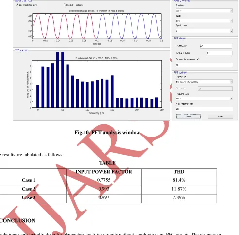
From FFT analysis of input current waveform shown in Fig.10, THD percentage is reduced further from 11.87% to 7.89% using this model. Due to the addition of dual boost converter as PFC controller, further reduction in THD is observed.
Fig.8. PMBLDC motor with PFC controller using dual boost converter
Fig.10. FFT analysis window
The results are tabulated as follows:
TABLE
INPUT POWER FACTOR THD
Case 1 0.7755 81.4%
Case 2 0.993 11.87%
Case 3 0.997 7.89%
V CONCLUSION
Simulations were initially done for elementary rectifier circuits without employing any PFC circuit. The changes in the input current waveform were observed and studied. A PFC circuit having a parallel boost converter was designed. The control strategy was based on average current mode control due to its relative advantages over voltage mode control and peak current mode control. Calculation of power factor was done for the purpose of comparison and to validate the improvement in power factor and THD ( for three different cases discussed. In case 2, the power factor has improved from 0.7755 to 0.993 and THD has reduced from 81.4% to 11.87%. Also in case 2, power factor has improved further from 0.993 to 0.997 and reduction of THD is from 11.87% to 7.89%.
0 0.02 0.04 0.06 0.08 0.1 0.12 0.14 0.16 0.18 0.2
-400 -200 0 200 400
Selected signal: 10 cycles. FFT window (in red): 5 cycles
Time (s)
0 50 100 150 200 250
0 1 2 3 4 5 6 7 Frequency (Hz) Fundamental (50Hz) = 503.2 , THD= 7.89%
REFERENCES
[1] P. VijayaPrasuna, J.V.G. Rama Rao, Ch. M. Lakshmi , “Improvement in Power Factor & THD Using Dual Boost Converter” International Journal of Engineering Research and Applications (IJERA) (2248-9622)
Vol. 2, Issue4, July-August 2012,
[2] Gishin Jacob George, Rakesh R, N.Arun, “PMBLDC Motor Drive with Power Factor
Correction Controller” International Conference on Computing, Electronics and Electrical Technologies
[ICCEET], 2012
[3] C. Umayal and S. Rama Reddy, „Modeling and Simulation of Closed Loop Controlled PFC Half Bridge Converter Fed PMBLDC Motor using Simulink‟ International Journal of Electrical Engineering. ISSN 0974-2158 Volume 4, Number 3, 2011.
[4] Sujaya.K, Heera Singh.R, B.C.S.Rao. Sathyanarayana, “Current control strategy for BLDC drive in satellite ground station”, International Journal of Applied Engineering Research, Dindigul, vol-2, No.1, 2011.
[5] Bhim Singh and Sanjeev Singh, “State of the Art on Permanent Magnet Brushless DC Motor Drives“ Journal of Power Electronics, Vol. 9, No. 1, January 2009
[6] Parillo.F, “Dual Boost High performances Power Factor Correction Systems(PFC)” November 2008, [7] Robert J. Gilleskie, San Diego Gas & Electric San Diego, “Harmonic and How they relate Power Factor”
Proc. of the EPRI Power Quality Issues & Opportunities Conference (PQA‟93), San Diego, CA, November
1993.
[8] Lorenzo Cividiano, “Power Factor, Harmonic Distortion, Causes, Effects and considerations” IEEE, 1992 [9] MILLER T.J.E. “Brushless permanent magnet and reluctance motor drive” (Clarendon Press, Oxford, 1989 [10] “SIMULINK, model based and system based design”.