R E S E A R C H
Open Access
DIHAT: Differential Integrator Handover Algorithm
with TTT window for LTE-based systems
Xianda Chen, Kyung Tae Kim, Byungjun Lee and Hee Yong Youn
*Abstract
Handover is one of the key operations in the mobility management of long-term evolution (LTE)-based systems. Hard handover decided by handover margin and time to trigger (TTT) has been adopted in third Generation Partnership Project (3GPP) LTE with the purpose of reducing the complexity of network architecture. Various handover algorithms, however, have been proposed for 3GPP LTE to maximize the system goodput and minimize packet delay. In this paper, a new handover approach enhancing the existing handover schemes is proposed. It is mainly based on the two notions of handover management:lazy handoverfor avoiding ping-pong effect andearly handoverfor handling real-time services. Lazy handover is supported by disallowing handover before the TTT window expires, while early handover is supported even before the window expires if the rate change in signal power is very large. The performance of the proposed scheme is evaluated and compared with two well-known handover algorithms based on goodput per cell, average packet delay, number of handovers per second, and signal-to-interference-plus-noise ratio. The simulation with LTE-Sim reveals that the proposed scheme significantly enhances the goodput while reducing packet delay and unnecessary handover.
Keywords:Handover (HO); Long-term evolution (LTE); Handover margin (HOM); Time to trigger (TTT); Reference signal received power (RSRP)
1 Introduction
Long-term evolution (LTE) refers to a new high-perfor-mance air interface in the third Generation Partnership Project (3GPP). 3GPP LTE is a purely packet-switched radio access telecommunication technology, providing excellent service for 4G networks at high data rate and low latency. The 3GPP was launched in December 1998 [1] and boosted to 380 member companies by 2011 [2]. The aim of 3GPP is to meet the needs on fast data trans-port media as well as high voice capacity. The require-ments of the next-generation networks targeted by LTE are peak throughput of 100 Mbps or more for downlink and 50 Mbps for uplink, respectively [3]. Besides higher bit rate and lower latency, power saving of user equip-ment (UE) is another important issue with LTE [4]. The LTE physical layer employs advanced technologies in-cluding orthogonal frequency division multiple access (OFDMA) and multiple input multiple output (MIMO) to transmit both data and control data between evolved
NodeB (eNodeB) and the UE. OFDMA is employed for downlink, and a special implementation of OFDMA called single-carrier frequency division multiple access (SC-FDMA) is employed for uplink in LTE with the aim of saving power [5,6].
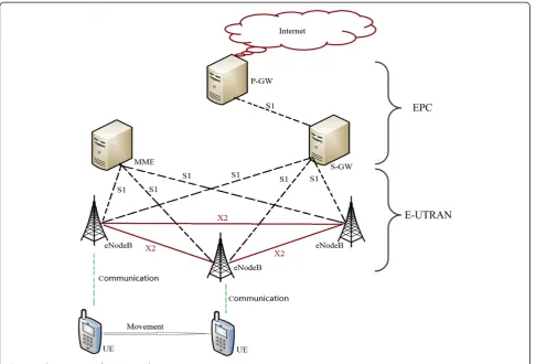
As illustrated in Figure 1, the LTE network consists of two main components: evolved packet core (EPC) and evolved UMTS terrestrial radio access network (E-UTRAN) [7]. EPC includes mobility management en-tity (MME), serving gateway (S-GW), and packet data net-work gateway (P-GW). The MME is a key control plane component which processes the signaling between the UE and core network, including authentication, authorization, bearer establishment, roaming, location registration man-agement, and S-GW/P-GW selection. The protocols run-ning in the MME are known as the non-access stratum (NAS) protocols. The S-GW performs data routing and forwarding between eNodeB and UE, which serves as a local mobility anchor for the data bearers when the UE moves between eNodeBs. The P-GW provides the UE with the access to an external packet data network by assigning an IP address to it. The EPC is a flat all-IP-based * Correspondence:[email protected]
College of Information and Communication Engineering, Sungkyunkwan University, Suwon, Gyeonggi 440-746, Korea
core network that can be accessed through the 3GPP radio access (HSPA, HSPA+, LTE) and non-3GPP radio access (e.g., CDMA2000, WiMAX), allowing handover procedures within and between both access types. The key module of E-UTRAN is eNodeB, which performs radio interface-related operations such as packet scheduling and handover. By integrating the radio controller function, eNodeB provides the air interface with the user plane and control plane protocol terminations towards the UE, min-imizing the latency and improving the efficiency.
In cellular mobile communication, the term handover refers to the process of transferring an ongoing call or data session from the source to the target base station. A handover algorithm is a handover decision-making process which triggers handover if certain conditions specified are satisfied. An efficient handover algorithm should make handover decision at the right time in case of keeping the communication with the source base station of poor quality or it would frequently trigger un-necessary handovers causing the ping-pong effect. The conditions for handover could vary over time due to the mobility of UE. Therefore, parameter optimization is of great significance to ensure efficiency and reliability of a handover algorithm.
There are two interfaces related to handover in E-UTRAN, which are S1 andX2 interface. The S1 inter-face connects eNodeB and EPC, while X2 provides the connection between two eNodeBs. Hence, the mobility management in LTE can be divided into mobility over S1 and mobility over X2. For intra-LTE mobility, the mobility within the LTE network, the X2 handover pro-cedure is normally used for inter-eNodeB handover. How-ever, if noX2 interface exists between two eNodeBs or the source eNodeB has been configured to initiate handover towards a particular target eNodeB through the S1 inter-face, the S1 handover is triggered [8]. Both S1 and X2 handover in LTE network are purely hard handover imple-mented with the purpose of minimizing the complexity of network structure. Note, however, that there exist some limitations with hard handover such as high data loss, high disruption time, and high carrier interferences [9].
The LTE systems focus on the services in the packet-switched domain to minimize the transmission latency while increasing the robustness of communication. Handover frequently occurs for the UEs of high move-ment speed, and thus, efficient handover is a crucial issue, especially for real-time services such as Voice over Internet Protocol (VoIP). In the traditional handover
scheme, the difference in the reference signal received power (RSRP) of host node and target node is obtained, which is then compared with the trigger threshold. In [10], a scheme called Integrator Handover Algorithm was proposed. It uses a special case of first-order auto-regressive moving average filter to integrate the filtered difference as another way of handover decision for real-time services. Handover is triggered immediately if the filtered difference is greater than the trigger threshold. As a result, the ping-pong effect can exist for a UE moving in and out of the cell boundaries. Introducing time-to-trigger window is to reduce the ping-pong effect. Handover, then, is triggered only when the difference is greater than the threshold during the entire window. Even with this mechanism, the handover decision cannot be made fast due to the window and integration-based operation, which is not desired for real-time services.
In order to further enhance the performance of the existing handover schemes, a new algorithm called Differ-ential Integrator Handover Algorithm with time to trigger (TTT) window (DIHAT) is proposed in this paper. It is mainly based on the two notions of handover manage-ment: lazy handover for avoiding ping-pong effect and early handoverfor supporting real-time services. DIHAT makes the handover decision when the difference in RSRP consistently exceeds the trigger threshold during the entire TTT window to avoid the ping-pong effect. In ad-dition to this, handover is triggered even before the TTT window is over if the rate of the change of the difference in RSRP is higher than another threshold (called rate threshold). This is to efficiently support real-time services. Various measures including goodput, handover frequency, and packet delay are interrelated in handover operation. In order to fairly and realistically evaluate the handover schemes, a new performance measure called effective throughput (EFFPUT) is devised in this paper. Along with the mathematical analysis of the proposed handover scheme, extensive experiments are conducted to evaluate its performance. It is also compared with two representa-tive handover algorithms, which confirms the relarepresenta-tive effectiveness of the proposed algorithm. The simulation results reveal that the proposed scheme greatly reduces the number of unnecessary handovers and packet delay and increases the system goodput and EFFPUT compared to the existing schemes.
The rest of the paper is organized as follows. Section 2 reviews the existing handover schemes, followed by the presentation of the proposed scheme in Section 3. Its performance is evaluated and compared in Section 4, and conclusions are made in Section 5.
2 Related work
In this section, various types of handover are presented first, and then the handover procedure of LTE is briefly
described. Next, two representative handover algorithms proposed for LTE are introduced, which will be evalu-ated and compared with the proposed scheme.
2.1 Types of handover
The handover techniques of wireless communication network are classified into two types: hard handover and soft handover. The reviews on hard and soft handover pro-posed for LTE are presented in the following subsections.
2.1.1 Hard handover
Hard handover algorithms are known as break-before -make, which means the old connection is broken from the serving eNodeB before a new connection is estab-lished to the target eNodeB. The UE communicates with only one eNodeB at any moment in time, making the network resource efficiently used. Another advantage of hard handover is that the UE hardware does not need to be capable of receiving two or more channels simul-taneously, which makes it cheaper and simpler. If the handover fails, however, the communication may come across abnormal termination since the re-establishment procedure to the serving eNodeB may not always be suc-cessful or a temporary disruption is caused even when it is successful.
A number of schemes based on hard handover had been proposed for LTE network. A mobility manage-ment module predicting the movemanage-ment direction of UE was presented in [11]. Handover decision is made by taking the movement direction and TTT into account. The prediction-based handover mechanisms were also proposed in [12,13]. A handover mechanism utilizing Doppler frequency estimation in the downlink was pro-posed for handling high-speed UE [14,15] improved the handover performance through inter-cell interference coordination (ICIC) maximizing the throughput at cell border. After coordinated multiple point (CoMP) was released in 3GPP Release 10, various handover schemes had been proposed based on CoMP [16-20]. CoMP technique provides multiple transmission and reception points among multiple cooperated eNodeB for each UE, by which inter-cell interference can be reduced and the frequency spectral efficiency is improved.
2.1.2 Soft handover
need to be occupied to support only a single connection, which reduces the number of available channels and thus deteriorates the capacity of the network. The net-work architecture also becomes more complex since a centralized controller is needed to perform handover control for each UE. Another cost is more complicated UE hardware required to process several channels in parallel.
Even though the soft handover technique was devel-oped for WCDMA network, the handover algorithms using dual-link had also been proposed for LTE network. The seamless handover schemes based on dual-link structure employing two antennas at the front and rear of a high-speed rail were presented in [21,22]. The rear antenna keeps the communication with the eNodeB as the front antenna executes handover, reducing the inter-ruption period and handover failure. Chang et al. [23] proposed a fractional soft handover scheme based on the carrier aggregation technique, in which the services are classified as VoIP and non-VoIP service. Here, the main idea is to partially perform soft handover for VoIP service but hard handover for non-VoIP service, mean-ing that non-VoIP service is only transmitted from source eNodeB or target eNodeB. The semi-soft over technique proposed in [24] utilizes a hybrid hand-over method for OFDM-based broadband network, termed as site selection diversity transmission (SSDT), permitting the advantages of both hard and soft hand-over for the services hand-over multicarrier-based network.
2.2 Handover in LTE
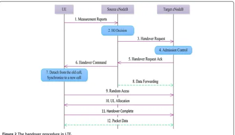
The handover procedure in 3GPP LTE is described in Figure 2. Each handover consists of three phases, which are preparation phase, execution phase, and completion phase [25]. In the preparation phase, the UE periodically sendsMeasurement Report(MR) to the serving eNodeB. Based on theMR, the serving eNodeB starts to negotiate with the target eNodeBs and decides which UE should be handed over. This operation is called handover deci-sion. The serving eNodeB sends Handover Request to the target eNodeB, which contains all the relevant hand-over information. The target eNodeB saves the context and responds to the serving eNodeB with Handover Re-quest Ack, which provides the information on the estab-lishment of a new radio link when the target eNodeB grants the resources. Once the preparation phase is completed, a handover command message is sent by the serving eNodeB to the UE in the execution phase, in-forming that the UE is going to handover to another eNodeB. Upon receiving the handover command mes-sage, the UE immediately releases the connection from the serving eNodeB and attempts to synchronize and access the target eNodeB by usingRandom Access(RA). At the same time, the serving eNodeB forwards all packets of the UE to the target eNodeB, which then transmits the packets to the UE through the target gateway. The hand-over procedure enters the completion phase after the target eNodeB receives the handover completion message sent from the UE [26,27]. The distributed control of the
LTE network requires the handover procedure to be effi-cient, which is of a great importance in typical mobile communication system. Unlike WCDMA, there is no need for centralized data manipulation in LTE since it does not support soft handover.
There exists a detach period for the UE under hand-over, which is between the disconnection from the serving eNodeB and successful connection to the target eNodeB. Forwarding the packets from the serving eNodeB to the target eNodeB during this period causes packet loss or packet delay.
2.3 Handover schemes
In this subsection, two representative handover schemes proposed for LTE are discussed, which will be evaluated and compared with the proposed scheme.
2.3.1 LTE hard handover algorithm
The standard hard handover algorithm is the default one used in the LTE system, which makes the handover deci-sion based on two variables: handover margin (HOM) and TTT [28]. HOM is a constant variable representing the threshold of the difference in the received signal strengths, RSRP in dB, between the serving eNodeB and target eNodeB. HOM identifies the most appropriate target eNodeB the UE should be handed over to. As-sume that a UE moves to the boundary of two eNodeBs. If HOM is adopted as an only measure for deciding the handover, then handover will continuously occur be-tween the two nodes. This is called ‘ping-pong effect’, and it significantly wastes signaling resources, decreases the system throughput, and increases the packet loss and pack delay. ATTT timer is thus used for reducing unnecessary handovers. The TTT timer is started when the RSRP of target eNodeB becomes larger than that of the serving eNodeB.
When a UE moves away from the coverage of the ser-ving eNodeB, the RSRP the UE receives from the current serving eNodeB decreases as time goes on. Meanwhile, the RSRP the UE receives from the target eNodeB will increase when the UE moves towards the target eNodeB. In this case, the UE should be transferred to the target eNodeB in order to avoid call termination when the UE stays outside the range of the serving eNodeB. A hand-over is triggered when Equation 1 is satisfied during the entire TTT window.
RSRPT >RSRPSþHOM ð1Þ
where RSRPT and RSRPS are the RSRP of the target eNodeB and serving eNodeB, respectively. Note that a handover is triggered after the TTT window expires during which the RSRP of target node is larger than that of the serving node at least as much as HOM.
2.3.2 Integrator Handover Algorithm
The Integrator Handover Algorithm (integratorHO) [10] uses trigger threshold and averaging factor to make the handover decision. The main feature of the algorithm is to integrate the differences of the RSRP between the tar-get and serving cell by using a special case of first-order auto-regressive moving average filter. The handover de-cision is made by comparing the filtered RSRP difference and the trigger threshold. Here, the filtered RSRP differ-ence at timet, FDIF(t), is calculated as follows:
FDIFð Þ ¼t ð1−αÞFDIFðt−1Þ þαDIFð Þt ð2Þ
where DIF(t) is the difference of downlink RSRP of the target eNodeB and serving eNodeB at time t. ‘α’ is the averaging factor (0≤α ≤1). DIF(t) is calculated by Equation 3.
DIFð Þ ¼t RSRPTð Þt −RSRPSð Þt ð3Þ
where RSRPT(t) and RSRPS(t) represent the RSRP of the target eNodeB and serving eNodeB at time t, respectively.
Upon the calculation of filtered RSRP difference dur-ing each measurement period, handover is triggered if the following condition is satisfied.
FDIFð Þt >FDIFThreshold ð4Þ
where FDIFThreshold is equivalent to HOM.
The averaging factor α and FDIFThreshold are two key factors dominating the performance of the integra-torHO algorithm. FDIF(t) is greatly influenced by the value of the averaging factorα. The FDIF(t) value would be more dependent on the value of the most recent DIF (t) when αis close to one. The integratorHO algorithm in this case focuses on the current quality of the chan-nel. In contrast, as the value of αgets close to zero, the FDIF(t) value would be more dependent on the past value, FDIF(t −1). Then, the integratorHO algorithm takes the past condition of the channel in account more than the current condition of the channel. The simula-tion results presented in [10] show that, when the FDIF-Threshold parameter is fixed, the higher the factorα, the more number of handovers. If the factor α is equal to one, the integratorHO algorithm makes handover deci-sion same as the LTE standard hard algorithm but with-out TTT window. Here, the instantaneous FDIF value most likely reaches FDIFThreshold and handover is trig-gered. If the factor α is too small, the current channel condition cannot be adequately measured and thus pro-per handover decision is hardly made.
is triggered immediately when Equation 4 is met. A higher value of FDIFThreshold discourages handover, causing delayed handovers. In contrast, ping-pong effect easily occurs with a small FDIFThreshold. Determining an appropriate value of FDIFThreshold will thus enhance the handover performance of the integratorHO algorithm. We next present the proposed DIHAT scheme which enhances the performance of the existing schemes.
3 The proposed scheme
In this section, the proposed scheme is introduced first, followed by mathematical modeling based on auto-regressive model.
3.1 The operational mechanism
The proposed DIHAT scheme makes the handover deci-sion when the integrated difference in the RSRPs con-sistently exceeds the trigger threshold during the entire TTT window to avoid the ping-pong effect. If the diffe-rence fluctuates such that it is sometimes larger but sometimes smaller than the trigger threshold during the window, the UE must be moving on the border of two cells and thus handover may not be necessary. Assume that the rate of the increase of the integrated difference in the RSRPs is higher than the rate threshold even be-fore the TTT window is over. This will happen when the UE quickly moves into the area managed by the target node. In this case, handover needs to be triggered to sup-port real-time services. In the proposed scheme, thus, the two conditions for triggering handover are either the inte-grated difference in the RSRPs consistently exceeds the trigger threshold during the entire TTT window or the rate of the increase of the integrated difference is higher than the rate threshold at any time. Figure 3 shows the re-lation between the factors used in the proposed handover operation.
As shown in Figure 3, RDIF(t) indicates the difference in the RSRPs of the UE between the target eNodeB, T, and serving eNodeB, S, calculated by Equation 5. HDIF(t) is defined as the difference between RDIF and HOM when the UE gets service from the serving eNodeB Sat timet, calculated by Equation 6.
RDIFð Þ ¼t RSRPTð Þt −RSRPSð Þt ð5Þ
HDIFð Þ ¼t RDIFð Þt −HOM ð6Þ
FRDIF(t) is obtained by Equation 7 using the first-order auto-regressive (FOAR) moving model during each measurement period. Similarly, FHDIF(t) is obtained by Equation 8. The use of FOAR allows high-channel qual-ity by considering the signal strengths in the previous handover measurement periods. The rate of increase of FHDIF(t), RI(t), is determined from Equation 9.
FRDIFð Þ ¼t ð1−βÞFRDIFðt−1Þ þβRDIFð Þt ð7Þ
FHDIFð Þ ¼t ð1−βÞFHDIFðt−1Þ þβHDIFð Þt ð8Þ
RIð Þ ¼t FHDIFð Þt −FHDIFðt−1Þ
FHDIFðt−1Þ ð9Þ
Here, FRDIF(t) and FRDIF(t−1) are the filtered values of RDIF(t) and RDIF(t −1), respectively. FHDIF(t) and FHDIF(t–1) follow the same convention. The relative importance of the current and prior measurement per-iod in deciding FRDIF(t) and FHDIF(t) is controlled by the averaging factor,β. Here, β is chosen depending on the measurement period (Tm) and TTT, asβ=Tm/TTT.
Note thatβis smaller than 1 since TTT is an integer mul-tiple ofTm. The initial value of FRDIF(t)/FHDIF(t) can be
defined either by averaging several RDIF(t)/HDIF(t) values of the previous periods or the first value of RDIF(t)/ HDIF(t) [29]. In the proposed DIHAT algorithm, it is set to zero.
With DIHAT, handover is triggered when the TTT window is over while the following condition is satisfied during the entire TTT window.
FRDIFð Þt >HOM ð10Þ
Handover is also triggered even before the TTT win-dow is over if and only if both Equations 11 and 12 are satisfied.
FHDIFð Þt >βHOM ð11Þ
RIð Þt >β ð12Þ
where FHDIF(t) is the filtered HDIF(t) value calculated by Equation 8. RI(t), calculated by Equation 9, indicates the rate of increase inFHDIF.
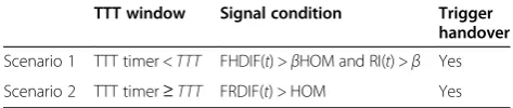
In summary, there are two different scenarios satis-fying the handover requirements as listed in Table 1, for
the UE when the TTT timer starts from the timeFRDIF becomes larger than HOM.
Although the TTT window can mitigate the wasteful ping-pong effect, it also can cause undesirable radio link failure (RLF) due to delayed HO. For the handover me-chanism not employing the TTT window, if a UE han-ded over to another eNodeB returns to the host shortly, the signaling resources are wasted substantially due to frequent channel connection operations and packet loss and delay are increased due to data forwarding. How-ever, lazy handover mechanism with too large TTT de-creases the system throughput since the UE misses perfect timing of handover to the target eNodeB of better quality but keeps the connection with the serv-ing eNodeB of poor quality. The optimal HO timserv-ing that produces the lowest ping-pong effect within al-lowable RLF rate vary depending on the speed of UE and the configuration of neighboring cells. The mag-nitude of HOM has a similar effect as TTT window. In the proposed DIHAT scheme, a smoothing factor
β is thus used to finely tune the operation. Even though TTT is small and thus β becomes close to 1, Equations 11 and 12 make conspicuous handover de-cisions considering not only the current quality of the channel but also the previous condition of the chan-nel and the rate of signal change.
3.2 Analysis of DIHAT
The auto-regressive (AR) model is a useful statistical tool often employed to examine the dynamic characteristics of time-series data [30]. The stationary property of AR allows one to understand and predict the values of fu-ture data using the previous time-series data. The AR(p) model can be described as Equation 13.
yt ¼
Xp
i¼1
θiyt−iþεt ð13Þ
where p is the dimension of the AR model and εt is the data series with zero-mean white noise.
To simplify the description of AR model, lag operator, x, is introduced. Then,yt−1can be described asxytand yt−p can be described as xpyt. Equation 13 can then be
simplified to Equation 14.
θð Þx yt ¼ εt ð14Þ
whereθ(x) is p-order regressive polynomial which is de-fined in Equation15.
θð Þ ¼x 1−θ1x−θ2x2−⋅⋅⋅−θpxp ð15Þ
θ(x) =0 is called the characteristic equation of the AR(p) model. The AR(p) model remains stationary if the molds of all solutions of the characteristic equation are greater than 1 [31]. The stationary AR(p) model is used to pre-dict the data having stationary property.
Theorem1. The proposed scheme based on the differ-ential integration approach using the FOAR model can provide accurate measure on the handover decision.
Proof. The first-order AR model, AR(1) or FOAR, is used in the proposed DIHAT scheme, which is shown in Equation 16. It is easy to get Equation 7, for example, if yt is changed to FRDIF(t), yt−1 to FRDIF(t −1), θ1 to (1−β) and εt to a random value, βRDIF(t).
yt ¼θ1yt−1þεt ð16Þ
Therefore, the characteristic equation becomes:
θð Þ ¼x 1−θ1x¼1−ð1−βÞx¼0 ð17Þ
The solution of Equation 17 is as follows:
x¼ 1
Hence, the AR(1) model provides a stationary stochas-tic process of FRDIF(t) and FHDIF(t). Note here that the FRDIF(t) and FHDIF(t) value are the indicators of chan-nel quality along with the previous values.
Recall that in the proposed DIHAT algorithm, hand-over is triggered if Equation 10 is met during the entire TTT window. This will not only reduce the probability of ping-pong effect but also allow high channel quality by continuously tracing the signal strengths. In addition, Equation 11 is checked if the filtered HDIF is large and Equation 12 is checked if the rate of signal change is larger than a threshold. Then, handover is triggered right away even inside the TTT window, which is important especially for real-time service.
We assume that the handover measurement period re-mains constant, and thus, the TTT window will be small if the averaging factor βis close to 1. Equation 10 indi-cates that the filtered RSRP difference between the target eNodeB and serving eNodeB is larger than HOM, which allows DIHAT to avoid ping-pong effect. Furthermore, the early-triggered handover decided by Equations 11 and 12 will allow quick but efficient handover. The per-formance of the proposed approach is evaluated next.
4 Performance evaluation
In this section, the metrics adopted for the perform-ance evaluation are introduced first. The structure of
Table 1 The handover satisfied scenarios
TTT window Signal condition Trigger
handover
Scenario 1 TTT timer <TTT FHDIF(t) >βHOM and RI(t) >β Yes
the simulated network and simulation parameters are then presented. Finally, the performance of DIHAT algorithm is evaluated and compared with the existing algorithms.
4.1 Performance metrics
The performance of the existing handover algorithms mentioned earlier and the proposed one are evaluated based on the following metrics: goodput per cell, packet delay, number of handovers per second, and received signal-to-interference-plus-noise ratio, average packet loss rate, and invalid packet rate.
Goodput is more important than throughput in the performance evaluation of meaningful operation since corrupted packets or excessively delayed packets con-tribute to the throughput but actually deteriorate the QoS. Average system goodput per cell (GDPUT) is de-fined as below.
where gdputi_jis the total size of the packets (in bit) cor-rectly received by UE_j at the serving cell_i, C is the total number of cells serving UE_j during the period of simulation, andJis the total number of UEs.
Average packet delay (DELAY) is defined as the aver-age system head-of-line (HOL) delay of the packets. The HOL delay of a packet is defined as the time interval between the arrival time of the packet at the buffer of eNodeB and its departure time. DELAY can be obtained by Equation 20.
where delayi_j is the total packet delay of UE_j at the serving cell_i and M is the number of packets all the UEs received during the simulation.
Average number of handovers per second (NHO) is another important performance metric. Every handover is initiated with a risk of failure. In general, reduction of handover frequency decreases the load of the system as well as minimizes the potential degradation of QoS caused by the detach time. However, the number of handovers cannot be blindly minimized to avoid disrupted service. There is thus always a trade-off between the number of handovers and other factors including goodput. NHO is calculated by Equation 21.
NHO¼N
T ð21Þ
where Nis the total number of handovers and T is the simulation time.
To check the QoS of real-time service, e.g., VoIP service tested in the simulation, average packet loss rate (PLR) and invalid packet rate (IPR) are also adopted as the performance metrics. PLR is a significant perform-ance metric for real-time service since retransmission is not allowed for any delayed packet. Here, invalid packets are defined as those arriving at their destination beyond the delay bound of 100 ms [32]. PLR and IPR indicate the degree of deterioration of the quality of a call ses-sion. PLR and IPR are obtained by Equations 22 and 23, respectively.
where packinvdis the total number of the packets arriving at their destination beyond the delay bound, packrecv is
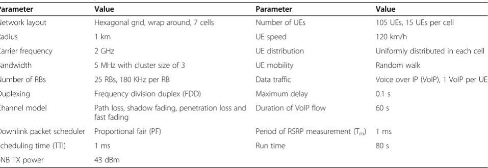
Table 2 The simulation parameters
Parameter Value Parameter Value
Network layout Hexagonal grid, wrap around, 7 cells Number of UEs 105 UEs, 15 UEs per cell
Radius 1 km UE speed 120 km/h
Carrier frequency 2 GHz UE distribution Uniformly distributed in each cell
Bandwidth 5 MHz with cluster size of 3 UE mobility Random walk
Number of RBs 25 RBs, 180 KHz per RB Data traffic Voice over IP (VoIP), 1 VoIP per UE
Duplexing Frequency division duplex (FDD) Maximum delay 0.1 s
Channel model Path loss, shadow fading, penetration loss and fast fading
Duration of VoIP flow 60 s
Downlink packet scheduler Proportional fair (PF) Period of RSRP measurement (Tm) 1 ms
Scheduling time (TTI) 1 ms Run time 80 s
the total number of received packets, and packsentis the total number of packets generated during the simulation.
4.2 Simulation environment
The simulator, LTE-Sim, is used to evaluate the perform-ance of the handover algorithms. LTE-Sim was devel-oped to simulate the uplink and downlink scheduling strategy in multicell/multiuser environment, taking into account user mobility, radio resource optimization, fre-quency reuse technique, adaptive modulation and coding module, and other aspects that are relevant to the indus-trial and scientific communities [33]. The simulation pa-rameters and their values are listed in Table 2.
A macro scenario with seven cells with the radius of 1 km is used as the target network of the simulation. The system has the bandwidth of 5 MHz and the cluster size is 3, and the available bandwidth is distributed among the clusters so that the cells belonging to a same cluster have no overlapping channels. This is an implementation of frequency reuse technique. The carrier frequency is 2 GHz with 25 resource blocks (RBs).
Path loss, shadow fading, penetration loss, and frequency-selective fast fading are included in the channel realization. The path loss is modeled based on the distance between the UE and eNodeB in kilometers by the formula (Path loss =128.1 + 37.6log10(d)) with a center frequency of 2 GHz [34]. As a default, shadow fading has been modeled through a log-normal distribution with the mean value of 0 and the standard deviation of 8 dB. The penetration loss is set to a default value of 10 dB. The fast fading model for the propagation is implemented with the Jakes model for Rayleigh fading [33].
Table 3 The ranges of parameter values
Parameter Value
HOM {1,2,3,…,10} dB
TTT {1,2,3,4,5} ms
4.3 Simulation results
In this subsection, the performance of the proposed scheme is evaluated and compared with the two repre-sentative schemes discussed in Section 2.3.
4.3.1 Effectiveness of DIHAT
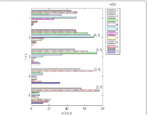
The performance of a handover scheme greatly varies according to the values of HOM and TTT. In order to conspicuously decide the values of them allowing the best performance of the proposed DIHAT algorithm, a new performance criterion called EFFPUT is devised. EFFPUT is obtained by Equation 24.
EFFPUT¼ GDPUT
NHODELAY ð
24Þ
Note that the larger EFFPUT, the better the system performance. This is because GDPUT is desired to be maximal, while NHO and DELAY are desired to be minimal.
The ranges of HOM and TTT are listed in Table 3, which are based on the parameters adopted in [35] for standardHO and integratorHO. The best parameter values of [HOM, TTT] for DIHAT algorithm are the ones maxi-mizing the total system goodput and minimaxi-mizing handover frequency and packet delay.
Figure 4 shows the results of EFFPUT of the proposed DIHAT scheme with the ranges of the parameter values listed in Table 2 for the UE of the movement speed of 120 km/h. Observe from the figure that the best per-formance is achieved when [HOM, TTT] are [2, 5]. The pairs [2, 4], [3, 3], and [6, 2] also allow comparable performance.
4.3.2 Comparison of the performances
The performances of the existing schemes are also measured with the parameter values allowing the best performance for them [20]. They are shown in Table 4. Note here that the integratorHO scheme does not employ TTT, and thus, the TTT value is set to 0. Instead, another parameter α is used for it, and the optimal value for it is 0.25 [35]. The parameters [HOM, TTT] used for the proposed scheme are [2,5], and thus,β=Tm/TTT=1/
5 = 0.25.
Figure 5 shows the comparison of average cell goodput of the schemes. Observe that the proposed DIHAT displays better goodput than the other schemes. Note that DIHAT keeps track of the received signal power and decides handover when the filtered RSRP is consist-ently high during the entire TTT window. It also triggers handover if the rate of signal power increase is very high. This lets the UE communicate with eNodeB via strong channel, which allows the goodput to be higher than the others.
It can be observed from Figure 6 that both the pro-posed DIHAT scheme and integratorHO show small delay. When the received signal strength of the potential target eNodeB is high enough, they promptly trigger handover. This minimizes the packet delay. The latency of target eNodeB with varying signal strength causes
Table 4 The optimal [HOM, TTT] values for the algorithms
Parameter scheme standardHO integratorHO DIHAT
[HOM, TTT] [5,5] [6, 0] [2,5]
Figure 5The comparison of average cell goodputs.
Figure 6The comparison of average packet delays.
average packet delay of integratorHO to be slightly higher than DIHAT. The standardHO algorithm suffers the highest delay due to fixed TTT.
Figure 7 compares the number of handovers per second with the respective handover algorithm. Observe that the proposed DIHAT scheme reduces the frequency of handover compared with other schemes. It triggers handover early only when the rate of change in the sig-nal strength is quite high. In contrast, the integratorHO algorithm shows the highest probability of handover be-cause the TTT window is not used. It handovers a UE to an eNodeB only based on the signal power, and thus, it shows a slightly larger number of handovers than the standardHO scheme.
The EFFPUT of the three schemes are compared in Figure 8. It reveals that DIHAT is the most effective handover mechanism compared with standardHO and integratorHO based on goodput per cell, packet delay, and number of handovers per second. DIHAT maxi-mizes the goodput while minimaxi-mizes packet delay and unnecessary handover.
Figure 9 compares the packet loss rate of the three schemes. Observe that the proposed scheme shows the smallest packet loss rate among the schemes. Even with the consideration of the past channel condition by inte-grating the RSRP differences, the integratorHO scheme displays increased probability of dropped packets due
to frequent data forwarding from the serving to target eNodeB.
Figure 10 shows the comparison of the rates of invalid packet of the schemes. It can be seen that the proposed scheme shows very low invalid packet rate, so does the integratorHO scheme. Keeping the connection with the serving eNodeB of poor quality, the fixed TTT window mechanism of the standardHO scheme causes the packets to arrive at the destination late.
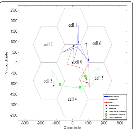
Figure 11 shows the trajectory of a UE movement with the standardHO, integratorHO, and DIHAT scheme. It can be seen that the UE with the integratorHO scheme experiences handover upon the leave from the area cov-ered by the radio range of the serving eNodeB. The UE with standardHO scheme triggers handover a little later after the UE crosses the boundary. Recall that the stan-dardHO scheme makes handover decision if the differ-ence in RSRP of the UE between the target and serving
Figure 8The comparison of EFFPUTs.
Figure 9The comparison of packet loss rates.
Figure 10The comparison of invalid packet rates.
eNodeB continuously exceeds HOM during the entire TTT window. On the contrary, observe from Figure 11 that the UE with DIHAT scheme is allowed a handover only when the increment of the signal strength is big enough. Notice that handover does not occur when the UE moves from cell 5 to cell 0 and then back to cell 5.
5 Conclusions
Handover is an essential operation in wireless network including LTE, especially for high-speed real-time ser-vice. Maximizing the goodput of the packets and minim-izing unnecessary handover are of great importance in this environment. Therefore, a new handover algorithm called DIHAT has been proposed in this paper. It em-ploys two policies for triggering handover, the signal po-wer of the target cell is consistently larger than the serving cell during the entire TTT window or the rate of increase in the signal power of the target cell is larger than a threshold even before the TTT window is over. Including the TTT window when manipulating the filtered RSRP to trigger handover can avoid unnecessary handover unlike integratorHO, while the early trigger mechanism can reduce the delay incurred by handover unlike standardHO when the target eNodeB has very high power strength. The simulation results show that the pro-posed DIHAT algorithm can reduce the number of hand-overs compared with the LTE standard hard handover algorithm and Integrator Handover Algorithm. It also allows higher goodput and lower packet delay than the two algorithms.
In the future, the performance of the proposed algo-rithm will be investigated with the consideration of QoS requirements of multimedia service and spectral efficiency. Also, the proposed DIHAT scheme will be improved to deal with the handover occurred in LTE-Advanced HeNet network in which Pico eNodeB’s (PeNBs) of lower coverage are deployed inside the coverage of the eNodeB.
Competing interests
The authors declare that they have no competing interests.
Acknowledgements
This research was supported by Basic Science Research Program through the National Research Foundation of Korea (NRF) funded by the Ministry of Education, Science and Technology (2013R1A1A2040257 and 2013R1A1A2060398), the second Brain Korea 21 PLUS project, and MSIP (Ministry of Science, ICT and Future Planning), Korea in the ICT R&D Program 2014 (1391105003).
Received: 14 January 2014 Accepted: 19 September 2014 Published: 7 October 2014
References
1. 3GPP Scope. http://www.3gpp.org. Accessed 25 September 2014 2. S Sesia, I Toufik, M Baker,LTE - The UMTS Long Term Evolution: From Theory
to Practice, 2nd edn. (John Wiley & Sons, Wiltshire, 2011)
3. 3GPP, Tech. Specif. Group Radio Access Network; Requirements for Evolved UTRA (E-UTRA) and Evolved UTRAN (E-UTRAN) (3GPP TR 25.913 V9.0.0), 2009
4. J Huang, F Qian, A Gerber, ZM Mao, S Sen, O Spatscheck, A close examination of performance and power characteristics of 4G LTE networks, inProceedings of IEEE 10th International Conference on Mobile Systems, Applications, and Services, 2012, pp. 225–238
5. J Zyren, W McCoy,Overview of the 3GPP Long Term Evolution Physical Layer
((Freescale Semiconductor, Inc, 2007). white paper). http://www.freescale. com/files/wireless_comm/doc/white_paper/3GPPEVOLUTIONWP.pdf. Accessed 25 September 2014
6. 3GPP, Tech. Specif. Group Radio Access Network; Evolved Universal Terrestrial Radio Access (E-UTRA); Physical channels and modulation (3GPP TS 36.211 V10.0.0), 2010
7. HG Myung,Technical Overview of 3GPP LTE(Polytechnic University of New York, 2008). http://tech-books-pdf.googlecode.com/git/LTE/3gppLTE.pdf. Accessed 25 September 2014
8. IF Akyildiz, DM Gutierrez-Estevez, EC Reyes, The evolution to 4G cellular systems: LTE-advanced. Phys. Commun3(4), 217–244 (2010) 9. I Shayea, M Ismail, R Nordin, Advanced handover techniques in
LTE-Advanced system, inProceedings of 2012 IEEE International Conference on Computer and Communication Engineering (ICCCE), 2012, pp. 74–79 10. N Zheng, J Wigard, On the performance of Integrator Handover Algorithm
in LTE Networks, inProceedings of IEEE 68th Vehicular Technology Conference (VTC 2008-Fall), 2008, pp. 1–5
11. FM Chang, HL Wang, SY Hu, SJ Kao, An efficient handover mechanism by adopting direction prediction and adaptive time-to-trigger in LTE networks, inProceeding of Computational Science and Its Applications (ICCSA), 2013, pp. 270–280
12. W Wanalertlak, B Lee, C Yu, M Kim, SM Park, WT Kim, Behavior-based mobility prediction for seamless handoffs in mobile wireless networks. Wirel. Netw17(3), 645–658 (2011)
13. H Ge, X Wen, W Zheng, Z Lu, B Wang, A history-based handover prediction for LTE systems, inProceedings of IEEE 2009 International Symposium on Computer Network and Multimedia Technology (CNMT 2009), 2009, pp. 1–4 14. O Altrad, S Muhaidat, PD Yoo, Doppler frequency estimation-based
hand-over algorithm for long-term evolution networks. IET Networks (2013). doi:10.1049/iet-net.2012.0224
15. D Aziz, R Sigle, Improvement of LTE handover performance through interference coordination, inProceeding of IEEE 69th Vehicular Technology Conference (VTC Spring 2009), 2009, pp. 1–5
16. CC Lin, K Sandrasegaran, X Zhu, Z Xu, On the performance of capacity integrated CoMP handover algorithm in LTE-Advanced, inProceeding of 2012 18th Asia-Pacific Conference on Communications (APCC), 2012, pp. 871–876
17. W Luo, R Zhang, X Fang, A CoMP soft handover scheme for LTE systems in high speed railway. EURASIP J. Wirel. Commun. Netw.1, 1–9 (2012) 18. X Xu, X Chen, J Lin,Handover mechanism in coordinated multi-point
trans-mission/reception system, in ZTE Communications, 2010. no. 1
19. CC Lin, K Sandrasegaran, S Reeves,Handover algorithm with joint processing in LTE-advanced, in Proceeding of IEEE 9th International Conference on Electrical Engineering/Electronics(Computer, Telecommunications and Information Technology (ECTI-CON), 2012), pp. 1–4
20. A Nagate, S Nabatame, D Ogata, K Hoshino, T Fujii, Field experiment of CoMP joint transmission overX2 interface for LTE-Advanced, in
Proceeding of IEEE 77th Vehicular Technology Conference (VTC Spring 2013), 2013, pp. 1–5
21. X Chen, C Li, Y Luo, A seamless dual-link handover scheme suitable for high-speed rail, inProceeding of 2013 IEEE International Workshop on High Mobility Wireless Communications (HMWC), 2013, pp. 91–95
22. T Lin, J Li, Y Huang, J Shi, J Zhou, Seamless dual-link handover scheme in broadband wireless communication systems for high-speed rail. IEEE J Selected Areas Commun.30(4), 708–718 (2012)
23. J Chang, Y Li, S Feng, H Wang, C Sun, P Zhang, A fractional soft handover scheme for 3GPP LTE-Advanced system, inProceeding of 2009 IEEE International Conference on Communications Workshops (ICC Workshops 2009), 2009, pp. 1–5
24. H Lee, H Son, S Lee, Semisoft handover gain analysis over OFDM-based broadband systems. IEEE Trans. Veh. Technol.58(3), 1443–1453 (2009) 25. 3GPP, Tech. Specif. Group Radio Access Network; General Packet Radio Service
(GPRS) enhancements for Evolved Universal Terrestrial Radio Access Network (E-UTRAN) (3GPP TS 23.401 V11.7.0), 2013
2012 IEEE International Conference on Information Networking (ICOIN), 2012, pp. 177–181
27. T Komine, T Yamamoto, S Konishi, A proposal of cell selection algorithm for LTE handover optimization, inProceedings of 2012 IEEE International Symposium on Computers and Communication (ISCC), 2012, pp. 37–42 28. K Dimou, M Wang, Y Yang, M Kazmi, A Larmo, J Pettersson, W Muller, Y
Timner, Handover within 3GPP LTE: design principles and performance, in
Proceedings of IEEE 70th Vehicular Technology Conference (VTC 2009-Fall), 2009, pp. 1–5
29. Ericsson, Proposed Reference Assumption for RSRP measurement Accuracy, 3GPP TSG-RAN WG4 Meeting #43 R4-070593(Kobe, Japan, 2007) 30. Autoregressive Model. http://en.wikipedia.org/wiki/Autoregressive_model.
Accessed 25 September 2014
31. M Stigler,Stationary Models: MA, AR and ARMA. http://macrofinance.nipfp. org.in/PDF/Lect2ARMA.pdf. Accessed 25 September 2014
32. 3GPP, Tech. Specif. Group Services and System Aspects; Policy and charging control architecture (3GPP TS 23.203 V11.7.0), 2012
33. G Piro, LA Grieco, G Boggia, F Capozzi, P Camarda, Simulating LTE cellular systems: an open-source framework. IEEE Trans. Veh. Technol.
60(2), 498–513 (2010)
34. 3GPP, Tech. Specif. Group Radio Access Network; Evolved Universal Terrestrial Radio Access (E-UTRA); Radio Frequency (PF) system scenarios (3GPP TS 36.942 V11.0.0), 2012
35. CC Lin, K Sandrasegaran, HAM Ramli, R Basukala, R Patachaianand, L Chen, TS Afrin, Optimization of handover algorithm in 3GPP long term evolution system, inProceedings of IEEE 4th International Conference on Modeling, Simulation and Applied Optimization (ICMSAO), 2011, pp. 1–5
doi:10.1186/1687-1499-2014-162
Cite this article as:Chenet al.:DIHAT: Differential Integrator Handover Algorithm with TTT window for LTE-based systems.EURASIP Journal on Wireless Communications and Networking20142014:162.
Submit your manuscript to a
journal and benefi t from:
7Convenient online submission
7Rigorous peer review
7Immediate publication on acceptance
7Open access: articles freely available online
7High visibility within the fi eld
7Retaining the copyright to your article

![Table 4 The optimal [HOM, TTT] values for the algorithms](https://thumb-us.123doks.com/thumbv2/123dok_us/955434.1116880/10.595.305.540.89.226/table-optimal-hom-ttt-values-algorithms.webp)