Speed Control Enhancement of a Chopper Fed Separately
Excited DC Motor Using Adaptive Neuro Fuzzy Controller
Ekta Sharma, Ankit Dubey
Department of Electrical and Electronics Engineering Chhattisgarh Swami Vivekanad Technical University, Bhilai, India
Abstract
The chopper fed speed control mechanism for the speed control of DC motor is the most widely used technique for providing speed control of DC motors. In the conventional chopper fed speed control mechanism,speed control of motor is performed by employing an additional conventional PI controller. At the steady state part, usually the performance of conventional PI controller, employed in the chopper fed speed control mechanism, is found satisfactory during the motor speed control. But, practically the performance of conventional PI controller based chopper fed speed control mechanism, during the speed control of DC motor is found very poor at the transient state and even takes higher settling time to settle down the speed of motor. To efficiently address this problem, this paper presents an Adaptive Neuro-Fuzzy Inference System (ANFIS) controller based chopper fed speed control mechanism for the enhancement of speed control of a chopper fed separately excited DC motor (SEDM). The basic idea of this work is to replace conventional PI controller (speed controller) in the chopper-fed DC motor drive by the adaptive neuro-fuzzy (ANFIS) controller to improve the speed control performance of the system.For the implementation and performance evaluation a versatile simulation package, MATLAB Simulink 2012(b) has been utilized.
Key words: Separately Excited DC Motor, Speed Control, Chopper fed control, MATLAB Simulink, PI controller.
1.
Introduction
High performance motor derives are necessary parts of industrial applications. A motor drive system with high performance has special characteristics such as good dynamic speed command tracking and load regulating response. DC motors are well known for their excellent control of speed for acceleration and deceleration.
In a DC motor the power supply directly connects to the field of the motor and causes a precise voltage control which is essential for applications which need control of speed and torque. Because of various advantages such as simplicity, ease of application, reliability and favorable cost, DC drives have long been a backbone of industrial applications. In comparison with AC drive systems DC drives are less and are normally cheaper for low horsepower ratings. DC motors are identified as adjustable speed machines for many years and a wide range of options have evolved for this purpose. Adjustable speed AC drives would be more complex and expensive.
D.C motor is considered as a SISO (Single Input and Single Output) system which has torque/speed characteristics and is compatible with most mechanical loads. By proper adjustment of the terminal voltage the mentioned characteristic makes a D.C motor controllable over a wide range of speeds [1]. In this paper an Adaptive Neuro-Fuzzy Inference System (ANFIS) controller based chopper fed speed control mechanism is proposed, for the enhancement of speed control of a chopper fed separately excited DC motor (SEDM). Computer Simulation isalso conducted to demonstrate the performance of the proposed controller and the conventional PI controller. The entire system is modeled using MATLAB Simulink 2012(b) software platform. A complete performance comparison between the proposed ANFIS based speed controller and conventional PI controller for different reference speeds is also presented.
2. Chopper Fed DC Motor Speed Control
The DC motor is the obvious proving ground for advanced control algorithms in electric drives due to the stable and straight forward characteristics associated with it. It is also ideally suited for trajectory control applications. From a control systems point of view, the DC motor can be considered as SISO plant, thereby eliminating the complications associated with a multi-input drive system [5].
2.1. Dynamics of a DC motor
Dynamics of a DC motor is described by the following equation:
( )
( )
( )
( )
p
di t
K
t
Ri t
L
V t
dt
ω
= −
−
+
…. (1)( )
( )
( )
( )
l l f
d
t
K i t
J
D
t
T t
T
dt
ω
ω
=
+
+
−
…. (2)Where the parameters of the DC motor are shown in Table 1.
2.2Chopper Fed DC motor Drive
A DC motor consists of stator and armature winding in the rotor as in Fig. 1. The armature winding is supplied with a DC voltage that causes a DC current to flow in the winding. The field circuit of the motor is excited by a constant source. The steady state speed of the motor can be described as:
l
V
iR
K
ω
=
−
…. (3)Where 𝑘𝑙is the duty cycle. The speed of a DC motor can be controlled by varying the voltage applied to the terminal. These can be done by using a pulse-width modulation (PWM) technique as shown in Fig. 2, where 𝑇is the signal period, 𝑡𝑑is the pulse-width, and 𝑉𝑚is the signal amplitude. A field voltage signal with varying pulse-width is applied to the motor terminal.
Figure (1). Dynamic equivalent circuit of a DC motor.Figure 2. Pulse width modulation. The average voltage is calculated from
0
1
( )
Tag m l m
td
V
V t dt
V
K V
T
T
=
∫
=
=
…. (4)It can be mentioned from these equation that the average DC component of the voltage signal is linearly related to the pulse width of the signal, or the duty cycle of the signal, since the period is fixed. The PWM voltage waveform for the motor is to be obtained by using a special power electronic circuit called a DC chopper. The action done by the DC chopper is supplying a train of unidirectional voltage pulses to the armature winding of the PM-DC motor as shown in Fig. 2. If 𝑡𝑑is varied keeping 𝑇constant, the resultant voltage wave represents a form of pulse width modulation, and hence the chopper is named as the PWM chopper [13, 14]. The block diagram representation of the speed control system for chopper fed DC motor with conventional PI speed controller is shown in Fig. 3.
Figure 3. Chopper fed DC motor with conventional PI speed controller.
3. Proposed Adaptive Neuro Fuzzy Inference System (ANFIS) Based Chopper Fed Speed
Control Mechanism
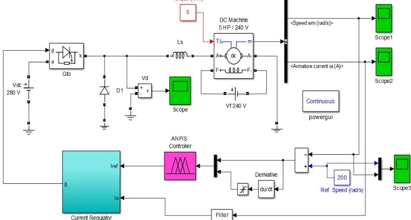
This subsection briefly describes the implementation of the proposed ANFIS based chopper fed speed control mechanism for DC motor speed control along with the development of the proposed ANFIS controller. The proposed modified chopper fed speed control mechanism based on ANFIS controller is shown in figure (4).
Figure (4)Block diagram of the Proposed ANFIS controller based chopper fed speed control mechanism. 3.1 Development of Proposed ANFIS Controller
For the development of proposed ANFIS controller following steps have been employed: Step-1. Obtain the input and outputs of conventional PI controller.
To model required ANFIS controller we have to first analyze the deficiency of conventional PI controller during control processes. To analyze the control signal generated by PI controller let us take reference speed to 200 rad/sec. Figure (5) shows the difference between reference speed and actual speed of motor, which is actually input of PI controller, and Figure (6) shows control signal generated by PI controller in response to the difference between reference speed and actual speed. During the simulation of the chopper fed speed control model with PI controller given in figure 6.4, load torque has been fixed at 5 Nm.
Figure (5) PI Controller Input.Figure (6) PI Controller Output.
Step-2.The next and important step is to identify the input variables for the designing of proposed ANFIS controller. To generate efficient speed control capability, two different inputs namely, difference in speed ie. Speed error and change in speed error have been used as two inputs for proposed ANFIS controller.
Step-3.Now after selection of inputs to the ANFIS controller, make a correction on output of conventional PI controller, which will provide our desired speed control.
Step-4. Train the ANFIS for obtained new input and output data.
Step-5.Test the developed and trained ANFIS.
By following above steps proposed ANFIS controller has been successfully developed, whose parameters are given as:
name: 'vst'
type: 'sugeno'
andMethod: 'prod'
orMethod: 'probor'
defuzzMethod: 'wtaver'
impMethod: 'prod'
aggMethod: 'sum'
input: [1x2 struct]
output: [1x1 struct]
rule: [1x4 struct]
After the successful development of ANFIS controller figure (7) and figure (8) shows its input variables membership function (MF) plot.
Figure (7) First Input MF’sof vst.fis. Figure (8) Second Input MF’sof vst.fis. The rule base generated for proposed ANFIS (vst.fis) Controller contains 4 rules, is given as:
0 0.5 1 1.5 2 2.5
-50 0 50 100 150 200
Time in Sec
S pe e d E rr or
Input of PI Controller
0 0.5 1 1.5 2 2.5
0 5 10 15 20 25 30 C ont rol S igna l G e ne ra te d by P I C ont rol le r
Time in Sec Output of PI Controller
0 20 40 60 80 100 120 140 160 180 0 0.2 0.4 0.6 0.8 1 e D eg ree o f m em b er sh ip in1mf1 in1mf2
1. If (e is in1mf1) and (de is in2mf1) then (output is out1mf1) (1) 2. If (e is in1mf1) and (de is in2mf2) then (output is out1mf2) (1) 3. If (e is in1mf2) and (de is in2mf1) then (output is out1mf3) (1) 4. If (e is in1mf2) and (de is in2mf2) then (output is out1mf4) (1)
14T
After successful development of the proposed ANFIS controller, the modified chopper fed speed control strategy based on developed ANFIS controller for DC motor speed control in the form of its actual simulation model is shown in figure (9).
14T
Figure (9) Simulation Model for proposed ANFIS controller based Chopper fed speed control technique for speed control of DC motor.
4. Simulation Results and Discussions
This section presents results, obtained after simulation performed for the speed control performance evaluation of the conventional PI controller based chopper fed DC motor and proposed control mechanism. To analyze the performance of PI controller and Developed ANFIS controller let us vary the reference speed from 100 red/sec to 200 red/sec in 20 red/sec step change. Figure (10) to Figure (15) shows the comparative analysis of PI and ANFIS controller.
1) For Reference Speed = 100 red/sec.
Figure (10) Comparison of speed control of DC motor using PI and ANFIS controllers based Chopper Fed Speed Control Mechanism for reference speed = 100 rad/sec.
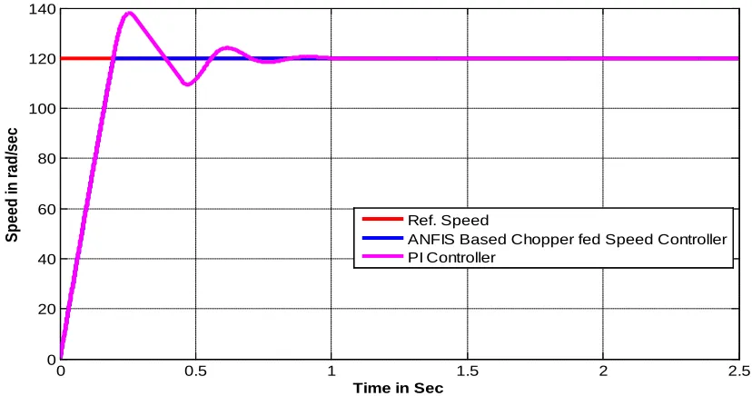
2) For Reference Speed = 120 red/sec.
Figure (11) Comparison of speed control of DC motor using PI and ANFIS controllers based Chopper Fed Speed Control Mechanism for reference speed = 120 rad/sec.
3) For Reference Speed = 140 red/sec.
0 0.5 1 1.5 2 2.5
0 20 40 60 80 100 120
Time in Sec
S
p
eed
in
r
ad
/sec
Ref. Speed
ANFIS Based Chopper fed Speed Controller PI Controller
0 0.5 1 1.5 2 2.5
0 20 40 60 80 100 120 140
S
p
eed
in
r
ad
/sec
Time in Sec Ref. Speed
ANFIS Based Chopper fed Speed Controller PI Controller
Figure (12) Comparison of speed control of DC motor using PI and ANFIS controllers based Chopper Fed Speed Control Mechanism for reference speed = 140 rad/sec.
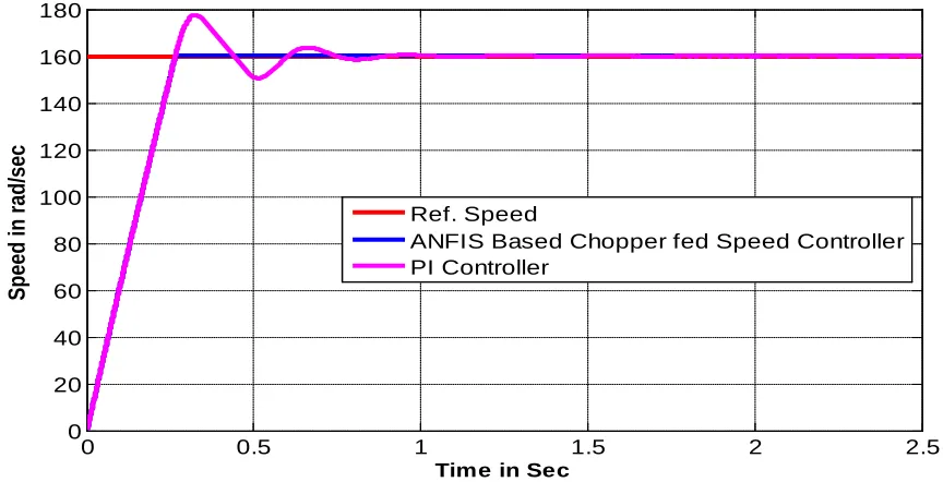
4) For Reference Speed = 160 red/sec.
Figure (13) Comparison of speed control of DC motor using PI and ANFIS controllers based Chopper Fed Speed Control Mechanism for reference speed = 160 rad/sec.
0 0.5 1 1.5 2 2.5
0 20 40 60 80 100 120 140 160
Spe
ed in rad/s
ec
Time in Sec
Ref. Speed
ANFIS Based Chopper fed Speed Controller PI Controller
0 0.5 1 1.5 2 2.5
0 20 40 60 80 100 120 140 160 180
Spe
ed in rad/s
ec
Time in Sec
Ref. Speed
ANFIS Based Chopper fed Speed Controller PI Controller
5) For Reference Speed = 180 red/sec.
Figure (14) Comparison of speed control of DC motor using PI and ANFIS controllers based Chopper Fed Speed Control Mechanism for reference speed = 180 rad/sec.
6) For Reference Speed = 200 red/sec.
Figure (15) Comparison of speed control of DC motor using PI and ANFIS controllers based Chopper Fed Speed Control Mechanism for reference speed = 200 rad/sec.
0 0.5 1 1.5 2 2.5
0 50 100 150 200
Spe
ed in rad/s
ec
Time in Sec
Ref. Speed
ANFIS Based Chopper fed Speed Controller PI Controller
0 0.5 1 1.5 2 2.5
50 100 150 200 250
X: 0.3375 Y: 200.8
Spe
ed in rad/s
ec
Time in Sec Ref. Speed
ANFIS Based Chopper fed Speed Controller PI Controller
From the resultent waveforms for speed control of DCmotor shown from figure (10) to figure (15), it is clearly observable that, in case of the conventional PI controller based Chopper Fed Speed Control Mechanism the DC motor speed curve takes a big overshoot during the trainsient state and takes approximately 1 sec to reach the specified reference speeds. While on the steady state side ie from 1sec to 2.5 sec, its response is quite good.
On the other side the results obtained for the proposed ANFIS based Chopper Fed Speed Control Mechanism,deployes that the developed ANFIS controller based Chopper Fed Speed Control Mechanism for speed control of DC motor, is able to provide higly efficient speed control in trasient as well as steady state operation. It is clearly evident from the comparative results plots that the proposed controller efficiently reaches to specified references speeds within 0.341 sec of settling time. The responses obtained for proposed controller is highly stable during the traisent as well as steady state portions. Therefore the proposed ANFIS controller based Chopper Fed Speed Control Mechanism for speed control of DC motor provides highly efficient and robust speed control for all the reference speeds. The settling time reduction by using the ANFIS controller based Chopper Fed Speed Control Mechanism is given by:
–
100
PI Settling Time
ANFIS Settling Time
Reduction in settling time
PI Settling Time
=
×
%1.077 – 0.341
100
1.077
Reduction in settling time
=
×
=
68.34
%5. Conclusion
The chopper fed speed control mechanism for the speed control of DC motor is the most widely used technique for providing speed control of DC motors. It has been valued more not only because it is the most used motor in industries but also due to their varied modes of operation. Also it has good self-starting capability, simple, rugged structure, low cost and reliability etc. Main property that makes it more useful for industries is its low sensibility to disturbance and maintenance free operation. In the conventional chopper fed speed control mechanism,speed control of motor is performed by employing an additional conventional PI controller. Usually the performance of that controller is found satisfactory during the motor speed control at the steady state. But it is often found that, practically the performance of conventional PI controller based chopper fed speed control mechanism, is very poor at the transient state and even takes higher settling time to settle down the speed of motor.
This paper forward an Adaptive Neuro-Fuzzy (ANFIS) controller for efficiently addressing the difficulties of the conventional chopper fed speed control of the DC motro and hence leads to the enhancement of speed control of a chopper fed separately excited DC motor (SEDM).
After the complete comparative analysis among the proposed ANFIS based chopper fed speed control mechanism and conventional PI controller based chopper fed speed control mechanism of DC motor speed for various references speeds, it is proved in the result section that, the speed control capability of the proposed technique is very robust and efficient as compare to conventional one. In addition to this it is also found that, the proposed speed control strategy not only provides highly controlled speed in the transient and steady state, but also takes 68.34 % less settling time as compare to conventional PI controller based chopper fed speed control mechanism.
References
1)
Jang JSR. Adaptive network based fuzzy inference systems. IEEE Trans Syst Man Cybern 1993:665–85.2)
Santana J, Naredo JL, Sandoval F, Grout I, Argueta OJ. Simulation and construction of a speed control for a DC series motor. Mechatronics 2002; 12(9-10):1145–56.3)
Minkova MD, Minkov D, Rodgerson JL, Harley RG. Adaptive neural speed controller of a dc motor. Electric Power Systems Research 1998; 47(2):123–32.4)
Lima AMN, Cavalcanti JHF, Deep GS. On-line training of adaptive neural network controllers. 20th Int Conf Ind Electron Control Instrum 1994;2(5–9 Sept):1392–5.5)
Madhusudhana Rao G, Sanker Ram BV. A neural network based speed control for DC motor. Int J Recent Trends Eng 2009;2(6).6)
Brandao Jacobina, C.; Rocha, N.; de Almeida Carlos, G.A.; Cipriano dos Santos, E., "Flexible Series/Parallel AC–DC–AC Motor Drive System," in0T0TIndustry Applications, IEEE Transactions on0T0T, vol.51,no.1, pp.259-270, Jan.-Feb. 2015.
7)
Rajasekhar, A.; Das, S.; Abraham, A., "Fractional Order PID controller design for speed control of chopper fed DC Motor Drive using Artificial Bee Colony algorithm," in0T0TNature and Biologically InspiredComputing (NaBIC), 2013 World Congress on0T0T, vol., no., pp.259-266, 12-14 Aug. 2013.
8)
Srivastava, S.; Pandit, V.S., "A scheme to control the speed of a DC motor with time delay using LQR-PID controller," in0T0TIndustrial Instrumentation and Control (ICIC), 2015 International Conference on0T0T, vol., no.,pp.294-299, 28-30 May 2015.
9)
Brito Palma, L.; Vieira Coito, F.; Gomes Ferreira, B.; Sousa Gil, P., "PSO based on-line optimization for DC motor speed control," in0T0TCompatibility and Power Electronics (CPE), 2015 9th InternationalConference on0T0T, vol., no., pp.301-306, 24-26 June 2015.
10)
Bara, A.; Dale, S.; Rusu, C.; Silaghi, H., "DC electrical drive control with fuzzy systems," in0T0TEngineeringof Modern Electric Systems (EMES), 2015 13th International Conference on0T,0T vol., no., pp.1-4, 11-12 June
2015.
11)
Rajeshkanna, G., "Modern speed control of separately excited DC Motor by Boost converter fed field control method," in0T0TComputer Communication and Informatics (ICCCI), 2013 International Conference on0T,0Tvol., no., pp.1-7, 4-6 Jan. 2013.
12)
Muruganandam, M.; Madheswaran, M., "Performance analysis of fuzzy logic controller based DC-DC converter fed DC series motor," in0T0TControl and Decision Conference, 2009. CCDC '09. Chinese0T,0T vol., no.,pp.1635-1640, 17-19 June 2009.