Ann Based Speed Control of BLDC Motor
with Reduced Switching Loss
Roshan Noushad
1, Prathibha P.K
2M.Tech Student, Department of Electrical Engineering, RSET College of Engineering, Ernakaulam, Kerala, India1
Professor, Department of Electrical Engineering, RSET College of Engineering, Ernakaulam, Kerala, India2
ABSTRACT: The paper is based on the artificial neural network based speed control of BLDC motor . The main purpose of this paper is to develop a low cost drive system for BLDC motor with reduced switching loss by the ANN. Due to the characteristics of the Brushless DC motor such as high efficiency, high power factor, high torque, low maintenance and ease of control, it is widely used in variable speed drives and industrial applications. The flexibility of the drive system can be increased by using ANN control. The BLDC motor is excited by a Four Switch Three Phase Inverter with minimum number of switches which in turn reduce the associated amount of switching losses. A simulation is carried out using MATLAB/SIMULINK
I. INTRODUCTION
BLDC motors are a type of AC motors which are widely used in various applications which include fan, pump or actuator applications. These are also employed in house hold appliances such as refrigerators, washing machines, computer peripherals etc. BLDC motor is commutated by an electronic commentator using power semiconductor switches. Due to the absence of brushes and commentator’s, BLDC motors require less maintenance and operate much more quietly than DC motors. These switches are not ideal and have switching losses and conduction losses which in turn reduce the e ciency of the drive. These losses can be minimized by reducing the number of switches in converters
or by using high performance processors. However a low cost drive system is an important consideration in the design and development of modern motor control drives.
Many researchers developed four switch BLDC motor drives in the PI controller topology .Here the controller part is a ANN(Artificial neural network) controller, which is the family of models inspired by biological neural networks (such as the central nervous systems of animals, in particular the brain) and are used to estimate. Artificial neurons are similar to their biological counterparts. They have input connections which are summed together to determine the strength of their output, which is the result of the sum being fed into an activation function. Though many activation functions exist, the most common is the sigmoid activation function, which outputs a number between 0 (for low input values) and 1 (for high input values). The resultant of this function is then passed as the input to other neurons through more connections, each of which are weighted. These weights determine the behavior of the network .These advantages of ANN is used for the controller of BLDC motor
II. FOUR SWITCH THREE PHASE INVERTER
Power circuit of the four switch three phase inverter BLDC motor is shown in Fig.1. The power inverter has 4 MOSFET switches, S1, S2, S3 and S4 and a split capacitor. The two phases A and B are connected to the two legs of
the inverter, while the third
phase C is connected to the centre point of dc link
capacitors, C1 and C2. The value of the capacitances C1 and
C2 are equal. Vc1 and Vc2 are the voltages across the DC
link capacitors (Vc1=Vc2). Vdc is the voltage across the
capacitor C1 and C2 (Vdc =Vc1+Vc2). A BLDC motor
needs quasi square current waveforms. Which are
synchronized with the back-EMF to generate constant
conducting regions. Also, at every instant only two phases are conducting and the other phase is inactive
A BLDC motor operates such that at a time only two phases are active and conducting current and the third phase is inactive. The Back Electromotive Force should have trapezoidal shape with 1200 conduction and 600 non conducting regions and the quasi square wave currents are needed to generate constant output torque so, it is required to have accurate rotor position. This can be obtained by three hall sensor signals. However, in the four-switch inverter, there are two legs (with two switches in each leg) which are
Fig.1 Four switch control of BLDC motor
connected to two motor windings and third phase of the motor is always connected to the midpoint of the dc-link capacitors, so that a small amount of current is always flowing. One high side and one low side power switches must be turned on but not simultaneously in the same leg. The four PWM signals are required to turn on the four switches in the inverter. The PWM waveforms are generated by using ANN controller. The voltage PWM scheme has six commutations. These are (S,0), (1,0), (1,S), (S,1), (0,1) and (0,S). The symbols in parenthesis are commutation signals of two controllable phases (phase A and B). “S” means the high side and low side power devices in the same leg are OPEN. “1” means the high side power device in this phase is switching in PWM and “0” means the low side device in this phase is switching in PWM.
Fig..2 Voltage vectors of four-switch converter. (a) (0, 0) vector, (b) (1, 1) vector, (c) (1, 0) vector, and (d) (0, 1) vector.
III. BLOCK DIAGRAM OF PROPOSED SYSTEM
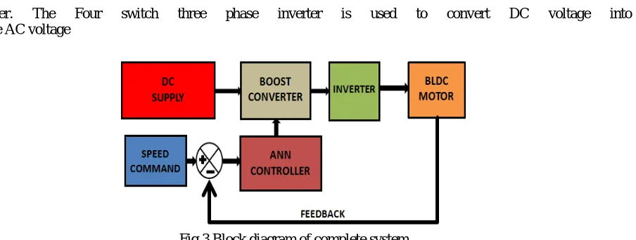
The proposed system block diagram is shown in fig.3. It
consists of boost converter,four switch three phase
inverter, ANN signal controller and three phase BLDC
converter. The Four switch three phase inverter is used to convert DC voltage into variable AC voltage
Fig.3 Block diagram of complete system
For hardware implementation atmega038P (Arduino Uno) Controller is trained for the ANN controller. Which acts as the controller of the system. It reads the p feedback depending upon speed signals from motor, implements and finally generates the pulses.
Three hall sensors are used to detect the rotor position. With three sensors we can obtain six commutation sequences.
One of the hall sensors changes the state for each 60 degrees
of rotation. Therefore it requires six steps to complete one
electrical cycle. At the end of each cycle, controller generates
four PWM signals. Difference between the actual and
required speeds is given as input to the controller. Based on
this data controller controls the duty cycle of the PWM
pulses which correspond to the voltage amplitude required
to maintain the desired speed and sends to four opto
couplers that isolate the control circuit and power circuit.
These outputs are given to the two MOSFET driver IC’s.
Each driver IC provides two pulses to drive one pair of
MOSFET switches. The switch drivers isolate and amplify
the controller commands and send to MOSFET inverter. The
inverter along with the position sensor arrangement is
functionally analogous to the commutator of a conventional
dc motor. The inverter generates trapezoidal back EMF
waveforms and quasi square wave currents to commutate
the motor. Commutation provides the creation of a rotational
field. Torque is produced because of the interaction of the
magnetic field generated by the stator coils and the
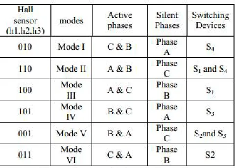
permanent magnets table 1 shows the relationship between
hall sensor signals and phase voltages, table 2 shows the switching sequences of Four-switch converter
Table 2 Switching Sequences Of Four-Switch Converter
IV. SIMULATION & ITS RESULTS
Fig .4 Simulation diagram based on ANN controller
The block diagram of complete simulation system is shown
in Fig.4 Digital computer simulation model
BLDC motor drive has been developed by using
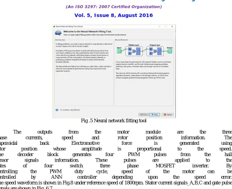
Fig .5 Neural network fitting tool
The outputs from the motor module are the three
phase currents, speed and rotor position information. The
trapezoidal back Electromotive force is generated using
rotor position whose amplitude is proportional to the speed.
The decoder block generates four PWM pulses from the hall
sensor signals information. These pulses are applied to the
gates of four switch three phase MOSFET inverter. By
controlling the PWM duty cycle, speed of the motor can be
controlled by ANN controller depending upon the speed error.
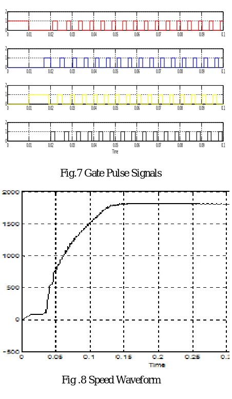
The speed waveform is shown in Fig.8 under reference speed of 1800rpm. Stator current signals_A,B,C and gate pulse signals are shown in Fig .6,7
Fig.6 Stator Current Signals_A,B,C
0 0.05 0.1 0.15 0.2 0.25 0.3
-50 0
50 Stator current ia
0 0.05 0.1 0.15 0.2 0.25 0.3
-50 0
50 Stator current ib
0 0.05 0.1 0.15 0.2 0.25 0.3
-20 0 20
Fig.7 Gate Pulse Signals
Fig .8 Speed Waveform
VI. CONCLUSION
Speed control of a four switch three phase inverter fed BLDC motor is done by using neural network. The software simulation is carried out using MATLAB/SIMULINK. The cost effective design can be achieved by employing four switch three phase inverter which has lesser switching losses. The usage of ANN controller results in a proper signal to the four switch inverter for the BLDC motor. Proper training of ANN controller improves the speed control of BLDC motor
REFERENCES
[1]Aspalli, M.S.;Munshi, F.M.;Medegar, S.L. ” Speed control of BLDC motor with Four Switch Three Phase Inverter using Digital Signal Controller ”.IEEE International Conference on Power and Advanced Control Engineering (ICPACE) 2015
[2] M. S. Aspalli, Farhat Mubeen. M Munshi, ”Digital Signal Controller Based Four Switch Three Phase Inverter Fed BLDC Motor Control”. International Journal for Scientific Research & Development(IJSRD) Vol. 2, Issue 07, | ISSN (online) 2014
[3] C.T. Lin, C.W. Hung, C.W. Liu,” Position Sensorless Control for Fourswitch Three-phase Brushless DC Motor Drives” , IEEE Transactions on Power Electronics, Vol. 23, No. 1, Jan. 2008
[4] Abraham, A. Meta-Learning Evolutionary Artificial Neural Networks, Neurocomputing Journal, Vol. 56c, Elsevier Science, Netherlands, (1–38)
2004
[5]Padmaraja Yedamale, “AN885: Brushless DC Motor
Fundamentals”, Microchip Technology Inc 2003
[6] Vincent Cheung,Kevin Cannons ,“An Introduction to Neural Networks ”,Natural Sciences and Engineering Research Council (NSERC),
May.2002
0 0.01 0.02 0.03 0.04 0.05 0.06 0.07 0.08 0.09 0.1
0 1 2
0 0.01 0.02 0.03 0.04 0.05 0.06 0.07 0.08 0.09 0.1
0 1 2
0 0.01 0.02 0.03 0.04 0.05 0.06 0.07 0.08 0.09 0.1
0 1 2
0 0.01 0.02 0.03 0.04 0.05 0.06 0.07 0.08 0.09 0.1
0 1 2