INPUT IMPEDANCE OF RECTANGULAR
MICROSTRIP ANTENNAS ON NON-RADIATING EDGES FOR DIFFERENT FEED SIZES
D. Mandal, R. Kar, and A. K. Bhattacharjee
Department of Electronics and Communication Engineering National Institute of Technology
Durgapur, India
Abstract—Closed-form expressions for the input impedance of half-wavelength rectangular microstrip antennas fed by coaxial connectors of different sizes at any point on any one of the non-radiating edges and open-circuited at the other ends are derived. Good agreement between computed and measured data is obtained.
1. SYMBOLS
Rin input resistance
Xin input reactance
Rin(nr) input resistance on non radiating edges [8]
Xin(nr) input reactance on non radiating edges [8]
a radiating edge
b Non-radiating edge/length of the rectangular microstrip antenna =
λg/2
λg guide wavelength
εr relative dielectric constant
h dielectric substrate thickness
εeff effective dielectric constant
frect desired resonant frequency of rectangular microstrip antenna
fr resonant frequency at which the rectangular microstrip antennas are to be designed for obtaining the desired resonant frequency
frect
d diameter of the feed size in inches
This paper shows the effect of feeding point at the edge (specially at the non-radiating edge). When the rectangular microstrip antennas are fed inside, the input impedance decreases.
2. INTRODUCTION
Microstrip antennas of different configurations like square, rectangular, circular, trapezoidal, elliptical, etc. are widely used because of their many advantages over conventional antennas such as low cost, light weight, reproducibility, ease of fabrication, etc. Several authors have studied [1–5] different characteristics on microstrip antennas. Closed-form expressions have been developed [6–8] for the input impedance of rectangular microstrip antennas. This communication attempts the development of empirical expressions for the input impedance of half-wavelength rectangular microstrip antennas for different feed sizes.
3. DESIGN
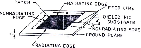
A number of rectangular microstrip antennas of variousa/hratios and of length λg/2 and fed at any point on any one of the non-radiating edges by coaxial connectors, were constructed on PTFE substrates of differentεrand hat the center frequency ranging from 1 to 10 GHz as shown in Figure 1. The values ofλg/2 were calculated from [9].
Figure 1. Rectangular microstrip antenna.
4. MEASUREMENTS
5. EMPIRICAL EXPRESSIONS FOR frect
frect values observed from the network analyzer for different feed sizes were different from fr because of the fringing field. frect values were plotted with the fr values with a/h, εr,|y| and d as parameters as shown in Figure 2. Using curve fitting technique [10], the following expression was obtained relating the frect and fr:
frect=frlog10
19 +a/b
2
1− εeff 14.33εr
1−b/2− |y| 6.32b
√
d+0.157
d0.32
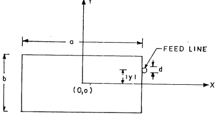
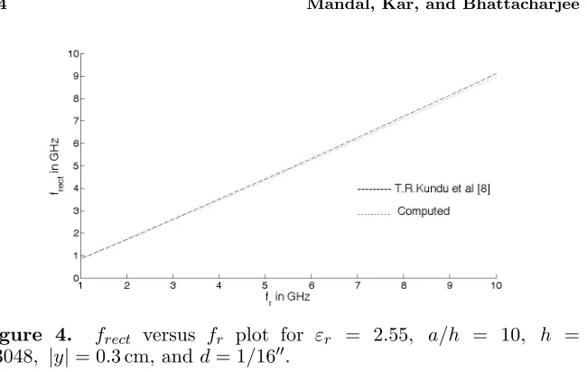
(1) Equation (1) has been developed with reference to the co-ordinate axis of Figure 3. frectvalues calculated withd= 1/16, using expression (1) were compared with the measured data of Kundu et al. [8] in Figure 4. The agreement was found to be excellent.
Figure 2. frect versusfr plot for various εr, a/h,|y|, and dvalues.
Figure 4. frect versus fr plot for εr = 2.55, a/h = 10, h = 0.3048, |y|= 0.3 cm, and d= 1/16.
6. EMPIRICAL EXPRESSIONS FOR Rin AND Xin
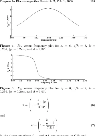
Rin andXin values measured from the network analyzer were plotted as a function of f, with εr, frect, a/h,|y|, and d as parameters. Some typical plots are shown in Figures 5 and 6. By the principle of curve fitting technique, the following expressions were obtained.
Rin=
√
d+ 0.06
d0.42
Rin(nr) (2)
and
Xin =
d−0.15
√
d + 1.35
Xin(nr) (3)
Where,
Rin(nr) =
Afrectεr
ε2
r+ 49.5
a h + 23
cos(∆fr)
6123.61 + 943.98(εr−2.55)|∆fr|2.6
1 + 2.8
|∆fr|
(4)
and
Xin(nr) =
Bfrectεr
ε2r+ 8.5 a
h + 23
sin(∆fr)
5588.77 (|∆fr|+ 0.005)
Figure 5. Rin versus frequency plot for εr = 6, a/h = 8, h = 0.254, |y|= 0.2 cm, and d= 1/8.
Figure 6. Xin versus frequency plot for εr = 6, a/h = 8, h = 0.254, |y|= 0.2 cm, and d= 1/8.
A =
1−
b
2− |y| 3.83b
(6)
and
B =
1−
b
2 − |y| 7.21b
(7)
In the above equationsfrect and ∆fr are expressed in GHz and
−0.05≤∆fr≤+0.05 2.55≤εr ≤10
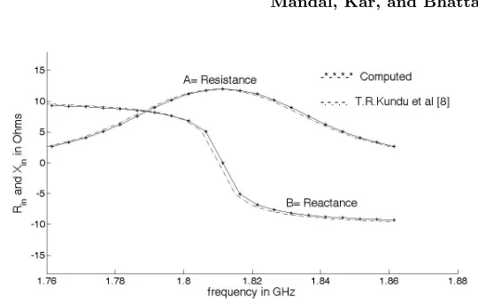
Figure 7. Rinand Xin versus frequency plot for εr = 10, a/h = 15, h= 0.154, |y|= 0.3 cm, and d= 1/16.
7. CALCULATION OF Rin AND Xin
Rin and Xin values of a rectangular microstrip antenna fabricated on a dielectric substrate havingεrwithin a certain range of values and for a frequency range of±0.05 Ghz around frect, fed at any point on any one of the non-radiating edges by coaxial connectors of different sizes may be calculated as follows :
Step 1. Substitute the value of the fr,|y| and d and obtain the corresponding value offrect from equation (1).
Step 2. Compute the values ofRinandXinfrom equations (2) and (3) respectively, with the known values offrect calculated in step 1.
8. RESULT
The theoretical values of Rin and Xin for the rectangular microstrip antennas were calculated using equations (1)–(3) and were compared with the measured data of Kundu et al. [8]. One typical plot is shown in Figure 7. The agreement was found to be excellent.
9. CONCLUSIONS
background in this area and that the computation time is negligible small.
ACKNOWLEDGMENT
The authors gratefully acknowledge ETCE Department, JU, Kolkata-32, West Bengal, India for providing measurement facilities.
REFERENCES
1. Saed, M. and R. Yadla, “Microstrip-fed low profile and compact dielectric resonator antennas,” Progress In Electromagnetics Research, PIER 56, 151–162, 2006.
2. Chair, R., A. A. Kishk, K. F. Lee, C. E. Smith, and D. Kajfez, “Microstrip line and cpw fed ultra wideband slot antennas with u-shaped tuning stuband reflector,”Progress In Electromagnetics Research, PIER 56, 163–182, 2006.
3. Shynu, S. V., G. Augustin, C. K. Aanandan, P. Mohanan, and K. Vasudevan, “Design of compact reconfigurable dual frequency microstrip antennas using varactor diodes,” Progress In Electromagnetics Research, PIER 60, 197–205, 2006.
4. Guney, K. and N. Sarikaya, “Resonant frequency calculation for circular microstrip antennas with a dielectric cover using adaptive network-based fuzzy inference system optimized by various algorithms,” Progress In Electromagnetics Research, PIER 72, 279–306, 2007.
5. Liu, S. F., X. W. Shi, and S. D. Liu, “Study on the impedance-matching technique for high-temperature supercon-ducting microstrip antennas,” Progress In Electromagnetics Re-search, PIER 77, 281–284, 2007.
6. Bhattacharjee, A. K., S. R. Bhadra Chaudhury, D. R. Poddar, and S. K. Chowdhury, “Equivalence of impedance and radiation properties of square and circular microstrip patch antennas,”Proc. IEE, Pt. H, 1989.
7. Deb, D., A. Gupta, S. Das, D. Patil, and A. K. Bhattacharjee, “Empirical expressions for the input impedance of rectangular microstrip antennas,”Microwave and Optical Technology Letters, Vol. 4, No. 6, 222–224, 1991.
on non-radiating edges,”Microwave and Optical Technology Let-ters, Vol. 33, No. 1, 28–31, 2002.
9. Schneider, M. V., B. Glance, and W. F. Bodtmann, “Microwave and millimeter wave hybrid integrated circuits for radio systems,”
Bell System Technical Journal, 1703–1725, 1969.