A Compact Multiband Bow-Tie Dipole Slot Antenna for WLAN
and WiMAX Applications
Jinjin Ge* and Long Jin
Abstract—A compact multiband bow-tie dipole slot antenna fed by coplanar waveguide (CPW)
is proposed in this paper. Multiple resonant mode technique and notch-band technique have been combined in this design to form triple-band operation just by adding single elements. Based on this, a pair of hairpin-shaped branches is implemented on each arm of the bow-tie slot antenna. A notch-band property is achieved compared with the original widenotch-band bow-tie antenna (without branches). Meanwhile, a new lower resonant frequency is obtained by using this kind of structure, which means that the size is compact in nature, and the triple-band operation is achieved. The notch-band and lower resonant frequency can be tuned by changing the length of the branch. The parameters of the antenna, including reflection coefficients, current distributions, radiation patterns and gain, are achieved by numerical simulations and measurements. The results indicate that the slot size of the proposed antenna is 52.4 mm×22.3 mm, and the proposed antenna can offer triple-band operation at 2.39–2.50 GHz (4.5%), 3.38–3.79 GHz (11.4%) and 4.87–6.23 GHz (24.5%), which is suitable for WLAN in the 2.4/5.2/5.8-GHz band and WiMAX in the 3.5/5.5-GHz bands.
1. INTRODUCTION
With the rapid development of modern wireless communication systems, antennas with multiband characteristics have attracted extensive attention. The use of multiband antennas makes it possible to integrate several wireless systems into a single platform, which means the reduction of cost and ease of use, especially in WLAN and WiMAX applications.
To generate multiple operating bands, the most popular approach is to introduce slots or add stubs in an ultra-wideband or wideband bow-tie antenna [1, 2] to achieve notch-bands and generate dual- or triple-band operating bands. In general, the design procedures of the ultra-wideband or wideband are relatively complicated. In addition, the width and length of these slots are sensitive to the bandwidths and the operating frequencies of the antenna. Another approach to achieving multiple operating bands is to embed slots with different shapes in the radiating patch or ground plane of the antenna [3, 4] or insert strips to a slot antenna [5, 6]. In [3], a slot technique is presented. Although the size of the antenna is determined by the middle resonant frequency, the size is large to some extent, and it has a relatively narrow bandwidth. For bow-tie slot antenna [5], by inserting a pair of metal strips near the ends of the bow-tie slot, two lower operating frequencies are obtained, and it is compact in nature. In [6], a number of slits are introduced on each arm of the antenna. Although multiple resonances have been generated, the gain of the antenna is greatly low compared to other similar antennas. However, there is no study to verify the rationality. Besides this, the work reported in [7] adopted circular parabolic curves and circles in the design of the radiating slot, and the CPW transmission line feeding the antenna was extended into the ground plane. By this way, the currents path is elongated, and surface currents traverse at both operating frequencies. This allows for a size reduction and dual-band operation.
Received 28 July 2015, Accepted 21 August 2015, Scheduled 31 August 2015
* Corresponding author: Jinjin Ge ([email protected]).
In this paper, a CPW-fed bow-tie slot antenna is proposed, which is capable of tri-band operation frequencies for WLAN and WiMAX, wide bandwidth and high gain. The bow-tie antenna, a planar version of the biconical antenna, is one example of a relatively simple, broadband planar antenna. For avoiding the requirement of a balanced feeder, the bow-tie antenna is changed into a bow-tie slot antenna, which means the allowance for the use of a CPW feeder. Coplanar waveguide (CPW)-fed lines have advantages such as broader bandwidth matching, low dispersion at higher frequency and coplanar capability [8]. The use of a CPW feeder also makes it easier to employ tuning structures and to use lumped components for impedance matching [7].
Besides this, a pair of hairpin-shaped branches is implemented in the design. By introducing this kind of structure on each arm of the bowtie antenna, a notch-band is generated on the original wideband bow-tie antenna (without branches). Meanwhile, a lower resonant frequency is obtained, which means that the size of the antenna can be further decreased.
2. STRUCTURE AND DESIGN OF THE BOW-TIE ANTENNA
The geometry and configuration of the proposed bow-tie antenna with a pair of hairpin-shaped branches are shown in Fig. 1. The antenna was constructed on an FR4 substrate with an effective dielectric constant of 4.4 and thickness h = 1.6 mm. The simulation and optimization were performed using ANSYS HFSS 15.0. The proposed tri-band bow-tie slot antenna is fed by a CPW with input impedance of 50 Ω.
It should be noted that the dimension of the conventional bow-tie antenna can be determined by the empirical formula [9]:
l= 1 2λ0×
1
√ε
eff
(1)
where, l is entire bow-tie antenna length, λ0 the wavelength in the air, andεeff the effective dielectric
constant, which can be obtained by:
εeff = εr+ 1
2 +
εr−1 2
1 + 10h
w
−0.555
(2)
where, εr is the dielectric constant of substrate, h the thickness of substrate, and w the line width of microstrip. The flare angle (α) and antenna input impendence (Zin) are related by [10]:
Zin= 120 ln
cotα 4
(3)
Due to the duality relation between the conventional bow-tie antenna and the slot bow-tie antenna, the slot dimension of the antenna can also be estimated by the empirical formula above. The proposed
W
L
WS
LS W1
W2
W4
W3
L1 L2 g
W5
L3 θ
Figure 1. Geometry of the proposed bow-tie antenna. Parameters of the proposed antenna are as
follows: W = 62.8 mm, L = 35.8 mm, W1 = 0.8 mm, W2 = 0.5 mm, W3 = 0.5 mm, W4 = 2.9 mm, W5 = 0.8 mm, Ws = 52.4 mm, LS = 22.3 mm, L1 = 14.0 mm, L2 = 10.8 mm, L3 = 18.0 mm, θ = 65◦,
antenna possesses triple-band operation, which is realized by generating a notch-band and a lower resonant mode on the original wideband bow-tie antenna (without branches). The hairpin-shaped branch has a total length ofL1+L2+W2/cos(θ). The relationship between the notch-band frequency (fN) and the length L1 can be described as:
L1≈ 1
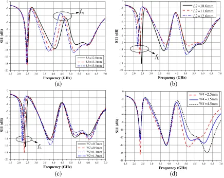
4λg(λg is guided-wavelength atfN) (4) The simulated reflection coefficients (S11) with varied shorter strip lengths (L1) are shown in Fig. 2(a). The notched frequency (fN) shifts to a lower frequency when L1 is increased from 12.8 mm to 13.8 mm, and the lower frequency is almost unaffected, which means that the notched frequency is mainly determined byL1. Thus lengthL1 can be tuned to obtain the required notched frequency (fN). In Fig. 2(b), S11 with varied lengths (L2) are simulated. With the increment ofL2 from 10.6 mm to 12.6 mm, the lower resonant frequency (fL) is shifted obviously, and the notched frequency (fN) is slightly changed for the coupling between L1 and L2. As shown in Fig. 2(c), S11 with varied lengths (W2) is also simulated. With the change ofW2 from 0.7 mm to 1.3 mm,fL is shifted obviously, andfN is unaffected. Thus fL can be tuned by adjustingL2 and W2.
Figure 2(d) demonstrates the effects of different positions of the branch. By changing the branch position W4, the impedance matching at lower resonant frequency becomes poor, whereas the higher centre frequency increases, and the bandwidth is broadened slightly.
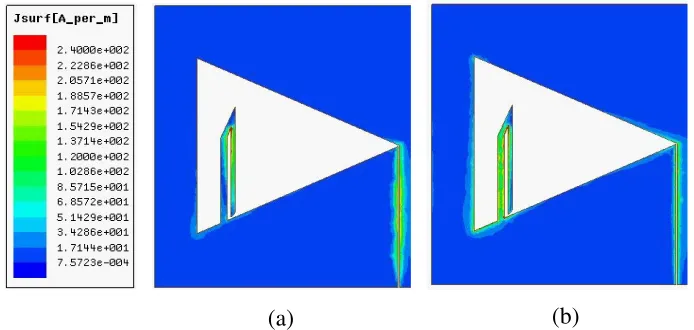
For further explaining the above discussion, Fig. 3 illustrates the surface current distributions of the proposed tri-band antenna at the lower resonant frequency (2.4 GHz) and notched frequency (4.5 GHz).
1.5 2.0 2.5 3.0 3.5 4.0 4.5 5.0 5.5 6.0 6.5 7.0 -20 -18 -16 -14 -12 -10 -8 -6 -4 -2 0 S11 (dB) Frequency (GHz) L1=12.8mm L1=13.3mm L1=13.8mm fN
1.5 2.0 2.5 3.0 3.5 4.0 4.5 5.0 5.5 6.0 6.5 7.0 -20 -18 -16 -14 -12 -10 -8 -6 -4 -2 0 S11 (dB) Frequency (GHz) L2=10.6mm L2=11.6mm L2=12.6mm fL
1.5 2.0 2.5 3.0 3.5 4.0 4.5 5.0 5.5 6.0 6.5 7.0 -20 -18 -16 -14 -12 -10 -8 -6 -4 -2 0 S11 (dB) Frequency (GHz) W2=0.7mm W2=0.9mm W2=1.1mm W2=1.3mm fL
1.5 2.0 2.5 3.0 3.5 4.0 4.5 5.0 5.5 6.0 6.5 7.0 -18 -16 -14 -12 -10 -8 -6 -4 -2 0 S11 (dB) Frequency (GHz) W4=2.5mm W4=3.5mm W4=4.5mm
(a)
(b)
(c)
(d)
Figure 2. Effect of varying branch parameters on reflection coefficient (S11). (a) Strip length (L1).
(b) (a)
Figure 3. Surface current distributions at (a)fN = 4.5 GHz, (b)fL= 2.4 GHz.
Fig. 3(a) shows that the surface currents at the notch frequency are much stronger in lengthL1, which means that the notch frequency is mainly determined by length L1. As seen in Fig. 3(b), the surface currents at the lower frequency (fL) mainly flow over the branches and the end of the bow-tie slot, and the surface currents distributed in length L2 and W2 are much stronger. Therefore,L2 and W2 play a leading role in generating the lower frequency.
According to the above discussions, the use of hairpin-shaped branches generates the combination of the multiple resonant mode technique and notch-band technique and makes the bow-tie slot antenna with tri-band performance possible. The design of the antenna begins with determining L1 and
L1+L2+W2/cos(θ), choosing fN and fL. W1,W3 and W4 are used to obtain a better input match. Because the optimized length L1 is longer than length L2, sharp corners are adopted in the design of antenna.
3. MEASUREMENTS AND DISCUSSION
The proposed antenna is simulated, fabricated and measured successfully. After fine optimizing by using ANSYS HFSS 15.0, the final antenna was manufactured. The fabricated bow-tie slot antenna with a pair of hairpin-shaped branches is shown in Fig. 4(a). The measurements for the fabricated antenna are performed by using Agilent E8363B Network Analyzer. The radiation patterns and antenna gain are also measured. The slot size of the proposed antenna is 52.4 mm×22.3 mm.
The simulated and measuredS11of the antenna with and without branches are shown in Fig. 4(b). As a comparison, the bow-tie slot antenna without any branches shows a wideband of 3.24–5.31 GHz with theS11less than−10 dB. It should be noted that the operating frequency of the conventional CPW-fed bow-tie slot antenna is determined by lengthWs. However, as hairpin-shaped branches are inserted into the bow-tie slot, the branches may change the original current paths, thus the bandwidth of the antenna with hairpin-shaped branches has been broadened. It is clear that the notched frequency bands are observed for the proposed antenna with the hairpin-shaped branches. The measured three bandwidths for the S11below−10 dB are 2.39–2.50 (4.5%), 3.38–3.79 (11.4%) and 4.87–6.23 GHz (24.5%), covering the 2.4/5.2/5.8-GHz WLAN and 3.5/5.5-GHz WiMAX applications. The measured S11 matches well with the simulated one in the notched frequency band, and a minor frequency shift is found in the middle frequency band. The errant effective dielectric constant may also lead to the shift of frequency and the change of bandwidth. Besides this, the fabrication tolerances, the mutual coupling introduced by connectors and soldering in the experiment have significant impact on the middle frequencies.
1.5 2.0 2.5 3.0 3.5 4.0 4.5 5.0 5.5 6.0 6.5 7.0 -25 -20 -15 -10 -5 0 S11 ( d B) Frequency (GHz) (a) (b) w/ branches(simulated) w/o branches(simulated) w/ branches(measured)
Figure 4. (a) Photograph of the fabricated antenna. (b) Measured and simulatedS11 of the antennas.
0 30 60 90 120 150 180 210 240 270 300 330 -30 -25 -20 -15 -10 -5 0 5 (a) 0 30 60 90 120 150 180 210 240 270 300 330 -25 -20 -15 -10 -5 0 5 10 (b) 0 30 60 90 120 150 180 210 240 270 300 330 -30 -25 -20 -15 -10 -5 0 5 (c) 0 30 60 90 120 150 180 210 240 270 300 330 -30 -20 -10 0 10 (d)
Figure 5. Radiation patterns of the prototype antenna measured at (a) 2.4, (b) 3.5, (c) 5.2 and (d)
measured at 2.4, 3.5, 5.2 and 5.8 GHz are 512, 5.10, 4.68, 4.75 dBi, respectively, while the simulated ones are 3.01, 5.26, 4.59, 4.72 dBi. The corresponding simulated radiation efficiencies obtained by using ANSYS HFSS 15.0 are 83.2%, 92.5%, 91.7% and 92.0%, respectively.
Table 1. Comparison with other multiband bow-tie antennas.
Effective size Bandwidths (GHz) Peak gains (dBi) [4] 1.35λg 3.47–3.51 (1.14%) 4.50–4.60 (2.2%) 1.1 (3.5 GHz)
[6] 0.57λg 2.57–2.63 (2.3%) 4.08–4.44 (8.5%) 1.72 (2.6 GHz)
This design 0.66λg 2.39–2.50 (4.5%) 3.38–3.79 (11.4%) 3.01 (2.4 GHz)
Further comparison with other multiband bow-tie antennas is shown in Table 1. The columns from left to right are respectively the effective size using the guided wavelength bandwidths at the lower and middle frequencies, and peak gains in the lower frequency. Here λg is guided-wavelength at lowest frequency. The bandwidths in this design have been improved at lower and middle frequencies. And the peak gain in the lowest frequency is also improved apparently. Compared with multiple resonant mode technique adopted in [4] and [6], the combining of multiple resonant mode technique and notch-band technique in this design reflects its advantages in size, notch-bandwidths and peak gains in the lowest frequency. In this design, by using notch-band technique, the lowest resonant mode is affected slightly. Therefore, it is possible to have wide bandwidths at middle and highest frequencies. However, the existence of other resonant modes has a large impact on the lowest resonant mode.
4. CONCLUSION
In this paper, a tri-band bow-tie slot antenna fed by a CPW for WLAN and WiMAX applications has been designed, fabricated, and tested with satisfactory performances. Multiple resonant mode technique and notch-band technique have been combined in this design to form triple-band operation just by adding simplified spiral-shaped branches. The proposed antenna can offer triple-band operation at 2.39–2.50 (4.5%), 3.38–3.79 (11.4%) and 4.87–6.23 GHz (24.5%). In all these bands, the antenna has good performances, including symmetric radiation pattern, typical dumbbell patterns in the E-plane and higher gains at operating frequencies. Besides this, the slot size is compact, the bandwidths and peak gains are improved apparently. In conclusion, all of these demonstrate that the proposed antenna is suitable for multifrequency applications of wireless communication systems.
REFERENCES
1. Dadgarpour, A., F. Jolani, Y. Yu, Z. Chen, B. S. Virdee, and T. A. Denidni, “A compact balanced antipodal bow-tie antenna having double notch-bands,”Microw. Opt. Technol. Let., Vol. 56, No. 9, 2010–2014, 2014.
2. Liu, H. W., X. P. Zhan, S Li, J. H. Lei, and F. Qin, “Dual-band bow-tie slot antenna fed by coplanar waveguide,” Electron. Lett., Vol. 50, No. 19, 1338–1340, 2014.
3. Liu, H. W., H. Jiang, X Guan, J. Lei, and S. Li, “Single-feed slotted bowtie antenna for triband applications,” IEEE Antennas Wirel. Propag. Lett., Vol. 12, 1958–1661, 2013.
4. Wu, M. T. and M. L. Chuang, “Multibroadband slotted bow-tie monopole antenna,” IEEE Antennas Wirel. Propag. Lett., Vol. 14, 887–890, 2015.
5. Chen, Y. C., S. Y. Chen, and P. Hsu, “A compact triband bow-tie slot antenna fed by a coplanar waveguide,” IEEE Antennas Wirel. Propag. Lett., Vol. 9, 1205–1208, 2010.
6. Garg, D. and S. Srivastava, “Multi band compact bow-tie slot antenna for WLAN applications,”
7. Berge, L., M. T. Reich, and B. D. Braaten, “A compact dual-band bow-tie slot antenna for 900-MHz and 2400-MHz ISM bands,” IEEE Antennas Wirel. Propag. Lett., Vol. 10, 1385–1388, 2011. 8. Zhou, S. W., P. H. Li, Y. Wang, W. H. Feng, and Z. Q. Liu, “A CPW-fed broadband circularly
polarized regular-hexagonal slot antenna with L-shape monopole,” IEEE Antennas Wirel. Propag. Lett., Vol. 10, 1182–1185, 2011.
9. Chang, D. C., Jr, H. Lee, and S. H. Lee, “The study of wideband bowtie antenna for ITDAMS,”
Microwave and Millimeter Wave Technology, ICMMT, 54–57, 2004.