Synthesis and Design of MMR-Based Ultra-Wideband (UWB) Band
Pass Filter (BPF) in Suspended Stripline (SSL) Technology
Mohamad Assaf*, Adnan Malki, and Alaa A. Sarhan
Abstract—This paper presents a direct synthesis approach for UWB BPFs. The modified Chebyshev filtering function is used to characterize the frequency response over the whole frequency range of the BPF. As for the filter’s circuit, open circuited MMR capacitively coupled with I/O ports is used, and two shunt short-circuited stubs are placed at the two ends of the connecting line to sharpen the rejecting skirt of the passband. The equivalent circuit’s transfer function is derived. By equating the filtering function to the transfer function of the circuit, the design parameters are obtained. The uniform connecting line is then replaced by nonuniform line to suppress spurious harmonics and achieve very wide stopband. In order to avoid critical precision requirement in the fabrication of the filter, we design the filter using suspended stripline (SSL) technology to replace the parallel-coupled microstrip lines (PCML) with very small coupling gaps. Finally, a filter prototype is designed and fabricated to experimentally validate the presented method. Experimental results show good agreement with EM-simulated and theoretical ones.
1. INTRODUCTION
Microwave filters with wide passband, low insertion loss, sharp attenuations, and extended stopband are highly desirable in building ultra-wideband (UWB) communication systems. Various structures and methods to design UWB bandpass filters have been reported in literature such as multiple-mode resonator (MMR), hybrid microstrip/coplaner-waveguide (CPW), cascaded high-low-pass filters technique, and using low-temperature co-fired ceramics (LTCC) or multilayer liquid crystal polymer (LCP) [1–5]. To improve skirt rejection, a stub-loaded multiple-mode resonator structure has also been suggested [6]. In the previous works the filters were designed by computer full-wave electromagnetic (EM) simulation and optimization of various parameters. However, exact synthesis has not been demonstrated. The synthesis approach for microwave filters is always highly demanded due to its unparalleled high efficiency in systematically determining the overall filter dimensions once the design specifications are given.
This paper presents a new circuit structure of UWB band pass filters (BPFs) based on the concept of MMRs as well as its corresponding synthesis method to exactly determine the design parameters for a set of required design specifications. The proposed UWB filter is designed using open-circuited stepped impedance resonator (SIR) with three sections, two high-impedance sections at two ends and one low-impedance section at the center. The resonator is capacitively coupled to the I/O ports by coupled lines. A pair of short-circuited stubs is installed in shunt at the two ends of the center section to generate two additional transmission zeros near the lower and upper cutoff frequencies and increase the selectivity. A total of six transmission poles have been achieved. The uniform center section of the UWB filter is to be replaced with an equivalent lowpass filter that passes the desired passband and
Received 16 March 2019, Accepted 22 May 2019, Scheduled 3 June 2019
* Corresponding author: Mohamad Assaf (assaf [email protected]).
rejects the spurious harmonics. In addition, the size of the proposed filter layout can be effectively reduced.
The fabrication requirements of tightly coupled lines translate to closely spaced PCML that are difficult to process. To alleviate these requirements, we implement the filter using suspended stripline SSL technology. Compared to a microstrip structure, the SSL structure has advantages of lower insertion loss and better temperature stability. Besides, no radiation occurs thanks to the fully shielded assembly of the SSL. Furthermore, the broadside coupling of the SSL could achieve a higher coupling coefficient which sometimes means a wider bandwidth.
To verify the proposed method, UWB BPF prototype with 100% FBW at 4 GHz center frequency is synthesized, modified to block spurious responses, designed, and fabricated on a suspended substrate RT/Duroid 5880 with a thickness of 10 mil. The theoretical analysis, EM-simulated performance, and measured results are included in this paper.
2. FILTER SYNTHESIS THEORY
The synthesis procedure mainly includes three steps. First, we derive the theoretical transfer function of the proposed filter based on its equivalent transmission line circuit. After that, a filtering function is selected as the target to fulfill the design specifications. Finally, equate the filtering function to transfer function and solve a set of nonlinear equations to obtain the circuit design parameters.
2.1. Circuit Analysis
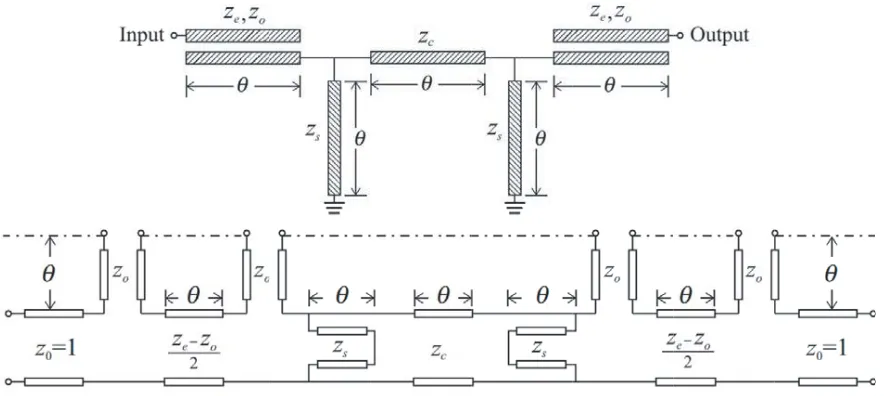
The basic configuration of the proposed MMR filter and its equivalent transmission line model are shown in Figure 1. The filter consists of SIR that is a cascade of high-low-high impedance transmission lines, and two shunt short-circuited stubs are attached at two ends of the connecting line. The coupled transmission lines represent the coupling sections between the resonator and the input/output lines. All lines are of lengthλg/4 at the center frequency of the passband. The equivalent circuit of parallel-coupled line is two series open-ended stubs which are cascaded through a connecting line [7]. The characteristic impedances of the series stubs and connecting line are indicated in terms of even and odd mode characteristic impedances of the coupled lineze,zo.
Figure 1. Schematic of the proposed filter and its equivalent circuit.
The transfer function of the filter can be expressed as follows:
|S21(θ)|2 =
1
whereθ is the electrical length, andFcir(θ) is defined as a characteristic function by
Fcir(θ) = TΓ (2)
The ideal transmission line circuit of the filter is a symmetrical two-port network. The characteristic function of such a network can be expressed in terms of its transmission matrix entries as:
Fcir(θ) = B−C
2 (3)
Now, we obtain the transmission matrix of the filter through the sequential multiplication of the transmission matrices of every constituting part of the filter. Then, after some tedious work we find the characteristic function of the filter as follows:
Fcir(θ) = k6cos
6θ+k
4cos4θ+k2cos2θ+k0
sin3θ (4)
k0 = −j
2z21zc
z2
1 −zc z12+zc
(5)
k2 = 2z2j 1zczs2
z2
s3z14+ 4z13z2+ 2z12z22−z12−2z1z2−z22
+2zczsz14+zsz31+z2zsz12−zsz1−z2zs
+z2cz14+ 2z2czsz21−1
(z1+z2) +zc2zs2z21+ 2z1z2+z22−3 (6)
k4 = −j
2z21zczs2
z2
s(z1+z2)2
3z12+ 2z1z2+z22−2
+ 2zczs(z1+z2)
2z13+ 2z12z2+ 2zsz21+ 2zsz1z2−z1+zsz22−z2−2zs
+zc2(z1+z2)2
2z21−1
+z2czs4z31+ 8z12z2+ 6z1z22−4z1+ 2z32−4z2
+z2czs22z12+ 4z1z2+ 2z22−3 (7)
k6 = j
2z21zczs2(z1+z2+ 1) (z1+z2−1) ((z1+z2) (zc+zs) +zczs)
2
(8)
zs, zc: the normalized impedances for the stubs and connecting line, respectively. z1,z2 are expressed
in terms of normalized even and odd mode characteristic impedances of the coupled line as:
z1 = ze−zo
2 (9)
z2 = zo (10)
The sixth-order polynomial indicates the appearance of six transmission poles. The MMR brings out two transmission poles, while two additional poles are contributed by the tightly coupled lines at input and output ports. Finally, the last two poles are introduced by the two shunt short-circuited stubs.
2.2. Ideal Filtering Function
The second step in the synthesis procedure is to choose an ideal mathematical filtering function that match the frequency response of the circuit. The modified Chebyshev filtering function was adopted to model the response of transmission line network with multiple stubs [8]. This filtering function has the following general form:
|S21|2=
1
1 +ε2cos2(nφ+qξ) (11)
whereεis the passband ripple factor. φand ξ are defined as:
cosφ = cosθ
cosθc (12)
cosξ = tanθc
where θc is the electrical length at the lower cutoff frequency of the first passband. It can be deduced that the second term in the denominator of modified Chebyshev function can be expressed as:
ε2cos2(nφ+qξ) =Pn+q(cosθ)
sinqθ
2 (14)
wherePn+qis the polynomial of degree (n+q) in cosθ. In order to make this polynomial have the same
format as the one in the denominator of the derived transfer function in the previous section, nand q should be chosen as n= 3,q = 3. Hence,
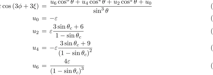
εcos (3φ+ 3ξ) = u6cos
6θ+u
4cos4θ+u2cos2θ+u0
sin3θ (15)
u0 = −ε (16)
u2 = ε
3 sinθc+ 6
1−sinθc (17)
u4 = −ε
3 sinθc+ 9
(1−sinθc)2 (18)
u6 =
4ε
(1−sinθc)3 (19)
To implement the synthesis procedure, the transfer function and filtering function are set to be equal. In this way, all the corresponding coefficients for the same factors of the two polynomials in Eqs. (4), (15) become the same.
|ki|=|ui| (20)
By solving this set of nonlinear equations, all the characteristic impedances are determined given the specified ripple factor εand cutoff radian frequencyθc.
3. FILTER DESIGN
To validate the synthesis theory mentioned above, a UWB filter with passband ripple level of 0.05 dB, 100% fractional bandwidth (θc =π/4), and 4 GHz center frequency is synthesized following the above described procedure. The characteristic impedances of the filter are calculated for 50 Ω terminating impedance as demonstrated in Table 1.
Table 1. Circuit parameters for the (0.05 dB equal ripple 2–6 GHz) UWB BPF.
Parameter ze zo zc zs
Value (Ω) 124.25 31.23 38.85 35.55
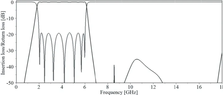
The theoretical performance of the circuit model with calculated characteristic impedances and θ=π/2 at center frequency 4 GHz is shown in Figure 2.
Synthesis procedure serves as a basis for preliminary design. Next in the design process, the filter needs to be adjusted since it suffers from unwanted spurious responses. These responses can be removed by replacing the uniform connecting line (center section of SIR) by equivalent nonuniform line that performs as a low-pass filter [9]. The configuration of this nonuniform line is shown in Figure 3.
The parameters of the nonuniform connecting line and coupled line are optimized to reject the spurious harmonics while maintaining the first passband. The ideal amplitude responses for the UWB BPF using nonuniform connecting lines are demonstrated in Figure 4.
Figure 2. Theoretical amplitude responses of the UWB BPF.
Figure 3. Non-uniform connecting line equivalent to low-pass structure.
4. SIMULATION AND EXPERIMENT
After synthesis procedure, the physical dimensions of the transmission line elements on SSL are computed using simulation software CST. After that, some tuning work has to be applied to these dimensions to approximate the theoretical response. The final SSL filter layout is shown in Figure 5.
Figure 5. Top and bottom layouts of the SSL UWB BPF.
A Duroid substrate with 0.254-mm thickness and dielectric constant 2.2 was chosen. The height from the substrate to the top of the cavity and from the substrate to the lower ground plane spacing is 1 mm. The channel of the coupled line section is 3 mm in width. An offset in overlapped coupled lines is introduced which offers extra degree of freedom in controlling the value of ze, zo. The shunt short-circuited stub is realized in SSL structure by simply connecting it to the shielding box (ground). The high impedance sections are easily achieved in SSL, while a ground metallization is added on the top layer of the substrate where low impedance sections are needed.
The full-wave simulation has been performed using CST. Figure 6 displays the results of circuit simulation and electromagnetic simulation. As can be noted, excellent agreement is obtained between the theoretical and simulated results. The SSL design is then fabricated and measured. Photographs of the bottom layer of the substrate and the filter with opened mount are displayed in Figure 7.
Figure 6. Theoretical and EM simulated amplitude responses of the modified UWB BPF.
(a) (b)
Figure 7. (a) Bottom and (b) top of the manufactured SSL UWB BPF with opened mount.
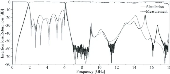
Figure 8. Predicted and measured amplitude responses of the SSL UWB BPF.
found larger than 10 dB in the desired passband. The 3-dB passband covers the range of 1.88–6.05 GHz, and it has a fractional bandwidth of 105.17%. The stopband rejection extends up to 18 GHz with insertion loss greater than 15 dB. In addition, the filter exhibits sharp rejection skirt near the cutoff frequencies.
5. CONCLUSION
In this work, an exact synthesis procedure for MMR-based UWB BPF has been forwarded. Mathematical formulation has been done to calculate characteristic impedances of the filter given targeted filter specifications. Synthesis procedure provides us with a design relatively close to the final one, which makes the design process very efficient. The design is then modified by replacing the uniform connection line by nonuniform one to remove the spurious passband and reduce the size of the filter footprint. Filter synthesis and design has been described in theory and verified by full-wave simulation and experiment. Good agreements are found among the theoretical, EM simulated, and measured results of the filter, and thereby validate the design principle.
ACKNOWLEDGMENT
REFERENCES
1. Zhu, L., S. Sun, and W. Menzel, “Ultra-wideband (UWB) bandpass filters using multiple-mode resonator,”IEEE Microwave and Wireless Components Letters, Vol. 15, No. 11, 796–798, Nov. 2005. 2. Wang, H., L. Zhu, and W. Menzel, “Ultra-wideband bandpass filter with hybrid microstrip/CPW structure,”IEEE Microwave and Wireless Components Letters, Vol. 15, No. 12, 844–846, Dec. 2005. 3. Hsu, C.-L., F.-C. Hsu, and J. Kuo, “Microstrip bandpass filters for ultra-wideband (UWB) wireless communications,” IEEE MTT-S International Microwave Symposium Digest, 4–682, Long Beach, CA, 2005.
4. Tang, C. and D. Yang, “Realization of multilayered wide-passband bandpass filter with low-temperature co-fired ceramic technology,” IEEE Transactions on Microwave Theory and Techniques, Vol. 56, No. 7, 1668–1674, Jul. 2008.
5. Hao, Z. and J. Hong, “Ultra-wideband bandpass filter using multilayer liquid-crystal-polymer technology,” IEEE Transactions on Microwave Theory and Techniques, Vol. 56, No. 9, 2095–2100, Sep. 2008.
6. Li, R. and L. Zhu, “Compact UWB bandpass filter using stub-loaded multiple-mode resonator,” IEEE Microwave and Wireless Components Letters, Vol. 17, No. 1, 40–42, Jan. 2007.
7. Matthaei, G., L. Young, and E. M. T. Jones,Microwave Filters, Impedance-matching Network, and Coupled Structures, Artech House, Dedham, MA, 1980.
8. Carlin, H. J. and W. Kohler, “Direct synthesis of band-pass transmission line structures,” IEEE Transactions on Microwave Theory and Techniques, Vol. 13, No. 3, 283–297, May 1965.