Design of the Permanent Magnet Linear Synchronous Motor
for High Thrust and Low Cogging Force Performance
Nur A. Mohd Nasir1, 2, Fairul Azhar1, 2, *, Raja N. Firdaus1, 2, Hiroyuki Wakiwaka3, Kunihisa Tashiro3, and Masami Nirei4
Abstract—Permanent magnet linear synchronous motors (PMLSM) are well known for its high thrust performance. However, such high thrust can be distorted by the existence of cogging force due to the attraction between stator core and permanent magnet (PM). To improve its performance, two parts of the PMLSM structure were considered during the design. They are PM magnetization arrangement on mover side and stator slot opening parameters on stator side. The designed models were simulated by using FEM software, and the performances of the models are then compared. The aim of the design is to achieve high thrust and low cogging force characteristics. Apart from average thrustFaveand cogging force Fcog, the performance of the PMLSM is also evaluated using average thrust Fave to cogging force ratio Fcog, called as thrust ratio. Based on the design, the highest thrust ratio Fave: Fcog, obtained from radial, axial and Halbach models, are 2.5032, 2.6262 and 1.8437, respectively.
1. INTRODUCTION
Linear motor provides direct linear motion with the absence of motion translator. The absence of motion translators such as gears [1], belts and ball screws [2] reduce the motor complexity and limitation. Linear motor extensive usage in many linear motion applications also contribute by their good performances such as high speed, high accuracy and maintenance-free operation [3]. There are three types of linear motor: linear stepper motor (LSTM), linear induction motor (LIM) and linear synchronous motor (LSM). There are two major types of LSM which are switch reluctance linear synchronous motor (SRLSM) and permanent magnet linear synchronous motor (PMLSM). The existence of permanent magnet as one of the magnetic flux sources makes the PMLSM have higher thrust density [4] hence makes it perform better than the SRLSM.
The thrust of PMLSM consists of three components which are main synchronous force, reluctance force and cogging force [5]. Synchronous force is the force applied when the supply frequency (Hz) to the stator is identical to the frequency of the mover called mover speed (m/s). As the mover moves, the direction of the force and moments are relatively with the direction of the mover. Thus, the excitation frequency in any plane, lateral to the axis of the stator, is locked to the speed of motion. For this reason, they are the synchronous force and moments. Synchronous force is a function of both the input voltage and the no-load voltage induced (EMF) [6]. On the other hand, the reluctance force is define as magnetic attraction that produced as the system tries to minimize energy stored and reduces the reluctance of the magnetic path [7]. The reluctance force depends on the synchronous reactance of the
d-axis,Xsd andq-axis,Xsq. In the non-salient pole motor, the synchronous reactance of thed-axis,Xsd
Received 19 October 2017, Accepted 17 November 2017, Scheduled 5 December 2017
* Corresponding author: Fairul Azhar bin Abdul Shukor ([email protected]).
is almost similar to the synchronous reactance of q-axis, Xsq(Xsd ≈ Xsq); therefore, reluctance force
is minimized and can be neglected [6]. Cogging force in the PMLSM can be caused by the interaction between PM and the stator core of the PMLSM [8]. On the other hand, the cogging can decrease the motor efficiency, motor controllability and motor average thrust force [9]. Therefore, in designing the PMLSM, besides observing the thrust characteristics, the cogging force also needs to be considered as a part in determining the model designed with the best performance characteristics.
2. BASIC PRINCIPLE OF THE PMLSM
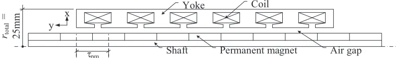
The PMLSM designed in this project is a cylindrical 6-slot, 8-pole type with three-phase supply. Fig. 1 shows the basic structure of the PMLSM. The PMLSM consists of six slots and a coil as stator. On the mover part, it consists of ring-shaped permanent magnets attached with a shaft. The PMLSM was designed within fixed total radius,rtotal which is 25 mm.
Coil Yoke
τpm Shaft Permanent magnet Air gap
y x rtota l = 25mm
Figure 1. Axial cross section of PMLSM basic structure.
Generally, the production of thrust in the PMLSM is influenced by electrical and magnetic sources. Electrical source normally depends on currentI fed to the coil. Meanwhile, for magnetic components, the thrust affected by magnetic flux density and inductance where these two elements are affected by flux of the PM and coil. The no-load rms voltage induced (EMF)Ef in one phase of armature winding
by PM excitation flux is given by Equation (1) [10] where N1 is the number of series per turn,kw the
armature winding coefficient, and Φf the magnetic flux produced by the PM in (Wb).
Ef =π
√
2f N1kwΦf(V) (1)
The fundamental harmonic of the excitation magnetic flux density Φf1 without armature reaction
is given in Equation (2) [10] whereLi is the effective length of stator core in (mm),Bmg1 the amplitude
of the first harmonic of the airgap magnetic flux density in (T), and τ the pole pitch.
Φf1 =Li
T
0
Bmg1sin
π
Tx
dx= 2
πτ LiBmg1(Wb) (2)
Because the armature core loss has been neglected, the electromagnetic power, Pelm, can be
determined by the difference between the input power, Pin, and the armature winding loss, ΔP1w.
Therefore, the electromagnetic power, Pelm, can be expressed by Equation (3) [10] where m is the
number of phase, V1 the input voltage in volt (V), Xsd the d-axis armature reactance (Ω), Xsq the q-axis armature reactance on (Ω), andδ the load angle betweenV1 andEf. This equation is derived at
the armature winding resistance, andR1 is equal to zero.
Pelm=m
V1Ef Xsd
sinδ+V
2 1
2
1
Xsq −
1
Xsd
sin 2δ
(W) (3)
Equation (4) shows the electromagnetic thrustFdx developed by a salient-pole PMLSM where vs
is the speed in (m/s), and by neglecting armature winding resistance the electromagnetic thrust,Fdxis
obtained as shown in Equation (5) [10].
Fdx = Pelm vs
(N) (4)
Fdx = m vs
V1Ef Xsd
sinδ+V
2 1
2
1
Xsq −
1
Xsd
sin 2δ
There are two components of electromagnetic thrust Fdx in salient pole-synchronous motor as
shown in Equation (6) where Fdxsyn is called the synchronous thrust in (N), and Fdxrel is known as
reluctance thrust in (N). Fdxsyn is the function of both input voltage V1 and the excitation EMF Ef
while Fdxrel depends only on input voltage V1 and also exists in unexcited machine (Ef = 0) provided
that d-axis synchronous reactance Xsd is not equal to q-axis synchronous reactance Xsq. However, for
surface configuration of PMs Xsd =Xsq (if the magnetic saturation is neglected), the electromagnetic
thrustFdx is given by Equation (7) [10].
Fdx = Fdxsyn+Fdxrel(N) (6)
Fdx ≈ Fdxsyn = m1 v2
V1Ef Xsd
sinδ(N) (7)
In general, it can be concluded that the electromagnetic thrust Fdx is influenced by input voltage V1 and EMF Ef. Since the input voltage V1 can be directly controlled by power supply, the design is
focused on EMFEf where it is influenced by excitation flux Φf.
3. DESIGN OF THE PMLSM
While the input voltage can be controlled directly by a power supply, the excitation flux Φf depends
on the designed magnetic circuit. Previously, the PMLSM has been designed in [11]. However, the designed model has drawbacks where the produced thrust F is saturated at lower rated current due to the saturation of magnetic flux density B on the stator part. Therefore, the stator of PMLSM has been designed in [12] to overcome the problems. In this research, the design of the magnetic circuit is performed by designing the PM magnetization direction arrangement on the mover and slot opening parameters on the stator of the PMLSM.
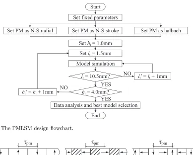
Figure 2 shows the design flowchart of the PMLSM. The design of the PMLSM was started by varying the PM arrangement, and they are radial, axial and Halbach models. For each PM arrangement, the slot opening parameters, which are length of stator slot openingltand height of stator slot opening ht were designed where the lowest value of the length of stator slot opening lt and the height of stator
slot openinghtwere set to 1.5 mm and 1 mm, respectively. The values of the length of stator slot opening lt and the slot opening height ht are then increased by 1 mm until they reached their respective limit
values. The designed PMLSM models were simulated by using FEM software, and the performances were evaluated and compared. Based on the performance, the best model was chosen.
3.1. Variation of PM Arrangement on Mover Side
There are three types of PM arrangement set in this paper. They are radial [13], axial [14] and Halbach [15]. Fig. 3 shows the three types of PM arrangement. Besides that, in order to make valid comparison, the PM pitch τpm and radius rpm were maintained to all the three of PM arrangement
in order to make a valid comparison of their performances. Therefore, PM width wpm for each PM
arrangement is changed accordingly as shown in Table 1.
Table 1. Permanent magnet dimensions.
PM arrangements PM width,
wpm (mm)
PM radius,
rpm (mm)
PM pitch,
τpm (mm) Shaft material
Radial 6 7 12 Ferromagnetic (SS400)
Axial 6 7 12 Non-ferromagnetic
Halbach 12 7 12 Non-ferromagnetic
Start
Set fixed parameters
lt = 10.5mm? Set PM as N-S stroke Set PM as N-S radial
Set ht = 1.0mm
Data analysis and best model selection
lt’ = lt + 1mm
ht = 4.0mm?
End
Set PM as halbach
Model simulation Set lt = 1.5mm
ht’ = ht + 1mm
YES
NO YES
NO
Figure 2. The PMLSM design flowchart.
(a) (b) (c)
τ
pmτ
pmτ
pmFigure 3. The three different PM arrangement; (a) radial, (b) axial, (c) Halbach.
also a bit different in order to optimize the flux path, flux leakage and magnetic flux density for each PM arrangement. Due to this fact, different shaft materials are used for different PM arrangements where a ferromagnetic shaft is used in radial array while both axial and Halbach arrays use a non-ferromagnetic shaft to reduce flux leakage. Besides, the axial array requires non-ferromagnetic spacer added between adjacent PMs. The ferromagnetic spacer is needed for flux conducting area hence increases magnetic flux density B produced by the PM. However, radial and Halbach arrays do not require any ferromagnetic spacer for flux path.
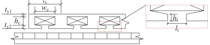
3.2. Design of Stator Slot Opening Parameters
There are two parameters of stator slot opening designed, which are slot opening length lt and slot
opening height ht. The position of the slot opening parameters is shown in Fig. 4. Apart from the slot
opening parameters, the other PMLSM structure parameters, such as airgap lengthδ and coil pitchτc,
were fixed and as listed in Table 2. The variations of stator slot opening parameters were applied to the three types of PM arrangement.
During designing slot opening parameters, the values of slot opening length lt and slot opening
height ht were varied starting from the lowest possible value and increased by 1 mm until they reached
maximum possible value. Table 2 lists the range of stator slot opening parameters. The limit of slot opening’s height depends on the value of lower stator yoke thickness ty2 which is 3 mm, whereas the
limit of slot opening’s length is determined by the value of coil width wc where in this case, the coil
widthwc is 10 mm. All the models were then simulated, and the performances obtained were compared.
ht
lt
τ
cwc
ty1
ty2
hc
Figure 4. PMLSM stator slot opening parameters.
Table 2. PMLSM structure parameters.
Structure parameters Value Total outer radius, rtotal (mm) 25
Coil pitch,τc (mm) 16
Permanent magnet pitch,τpm (mm) 12
Permanent magnet outer radius, rpm (mm) 13
Shaft radius,rs (mm) 6
Lower yoke thickness,ty2 (mm) 3
Upper yoke thickness,ty1 (mm) 2
Air gap length,δ (mm) 0.5 Coil resistance (per coil), R (Ω) 6.93
Coil turn (per coil), N 220 Length of slot opening,lt (mm) 1.5∼9.5
Height of slot opening, ht (mm) 1∼3
4. PERFORMANCE COMPARISON OF THE PMLSM
All the designed PMLSM models were simulated by using FEM software. Based on the obtained result, the performances of the PMLSM were observed and compared. Three performances of the PMLSM are compared. They are average thrustFave, cogging forceFcog, and ratio of average thrust to cogging force
Fave: Fcog or called as thrust ratio.
4.1. Comparison of Average Thrust, Fave
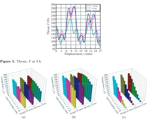
Generally, the performances of the PMLSM are evaluated based on thrust characteristics [17]. Therefore, all the PMLSM models with different slot opening parameters and PM magnetization direction arrangements are evaluated based on the thrust characteristics. Fig. 5 shows the sample of thrust for three different PM arrangements of the PMLSM. To evaluate the thrust F at certain current I
value, the average thrustFave is used. Therefore, based on thrustF characteristics obtained as Fig. 5, the average thrustFave is calculated using Equation (8).
Fave= 1
xT
x
0
F dx(N) (8)
where Fave is the average thrust in (N), F the thrust in (N), and x and xT are the instantaneous and maximum displacements, respectively in (m).
0 3 6 9 12 15 18 21 24 27 60
80 100 120 140 160 180 200 220 240 260 280 300
Th
ru
st
,
F
(N)
Displacement, x (mm)
R ad ial Ax ial
Hal ba ch
Figure 5. Thrust,F at 3 A.
(a) (b) (c)
Figure 6. PMLSM average thrust,Fave at 3 A; (a) radial, (b) axial, (c) Halbach.
average thrust produced by Halbach models decreases as the length of stator slot openinglt increases.
Oppositely, the average thrustFave produced by radial and axial models does not show a lot of changes over the changes of stator slot opening parameters.
Basically, the height of stator slot openinghtfor each variation of the length of stator slot opening ltdoes not give any significant difference towards thrust characteristics. This can be observed in Fig. 6
where Figs. 6(a), (b) and Fig. 6(c) show the thrust characteristics of the radial, axial and Halbach models, respectively. It is shown that the thrust produced by the same length of stator slot openinglt
with different heights of stator slot openinghtis almost constant with a small amount of differences.
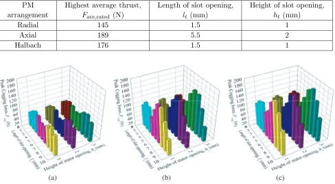
Based on average thrust presented in Fig. 6, the model that produced highest average thrust,Fave, on each PM arrangement was determined and compared in Table 3. Table 3 shows that the axial model with lt = 5.5 mm and ht = 2 mm has the highest average thrust which is 189 N. Meanwhile, for both
radial and Halbach arrays, the highest average thrust is produced by the models with lt= 1.5 mm and ht= 1 mm. The average produced thrusts are 145 N and 176 N, respectively.
4.2. Comparison of Cogging Force, Fcog
Apart from thrust F, the effect of stator slot opening parameters and PM arrangement variations are also evaluated based on the performance of cogging force, Fcog. Fig. 7 shows the cogging force Fcog
Table 3. Maximum average thrust for different PM arrangement.
PM arrangement
Highest average thrust,
Fave,rated (N)
Length of slot opening,
lt (mm)
Height of slot opening,
ht(mm)
Radial 145 1.5 1
Axial 189 5.5 2
Halbach 176 1.5 1
(a) (b) (c)
Figure 7. PMLSM cogging force,Fcog; (a) radial, (b) axial, (c) Halbach.
Based on Fig. 7, it is shown that overall radial models produce lower cogging forceFcog than axial and Halbach models. The cogging force Fcog characteristics of the radial models do not have much differences as the length of stator slot opening ltincreases, and the value is almost similar. Meanwhile,
compared to Halbach models, axial models produced lower cogging force, Fcog. Compared to radial, axial models show a large fluctuation of cogging force Fcog with variation of the length of stator slot opening lt, and this can be observed in Fig. 7(b). Similar to axial models, the Halbach models also
show a significant change of cogging forceFcog, as the length of stator slot openinglt is varied as shown
in Fig. 7(c).
Similar to thrustF characteristics as discussed previously, the variation of the height of stator slot openinghtdoes not give any substantial effect towards the characteristics of cogging forceFcog with the
same length of stator slot openinglt, as shown in Fig. 7. This can be seen in Fig. 7(a) and Fig. 7(c) for
radial and Halbach models, respectively. The differences are quite small, and the value of cogging force
Fcog is almost constant for the height of stator slot opening, ht, models with the same length of stator
slot opening, lt. However, some models in axial array show that the value of cogging forceFcog shows
significant differences as shown in Fig. 7(b). Fig. 7(b) shows that axial lt = 2.5 mm, 3.5 mm, 4.5 mm,
and 5.5 mm has big differences for different heights of stator slot opening, ht.
Based on Fig. 7(a), the radial models with the lowest and highest cogging forces were identified. The lowest cogging of the radial arrangement is produced by the model withlt= 1.5 mm andht= 2 mm
which is 57 N while the model with lt= 8.5 mm andht= 2 mm produced the highest cogging which is
100 N. Meanwhile, axial model withlt= 8.5 mm andht= 2 mm produced the highest cogging which is
169 N while the axial model withlt= 9.5 mm andht= 3 mm produced the lowest cogging which is 60 N.
The cogging force characteristic of the axial model is shown in Fig. 7(b). Fig. 7(c) shows the cogging force characteristic for the Halbach models. From Fig. 7(c), the Halbach model with lt= 7.5 mm and ht = 3 mm is identified to produce the highest cogging which is 186 N while the Halbach model with lt= 4.5 mm andht= 3 mm produced the lowest cogging which is 93 N.
Table 4. The lowest cogging force for different PM arrangement.
PM arrangement Lowest cogging force,
Fcog,min (N)
Length of slot opening,
lt (mm)
Height of slot opening,
ht (mm)
Radial 57 1.5 1
Axial 60 9.5 3
Halbach 93 4.5 3
summarizes that the radial model withlt = 1.5 mm and ht= 1 mm produced lower cogging force Fcog
than other PM arrangement models, which is 57 N. Meanwhile, the axial model with lt= 5.5 mm and ht = 2 mm has the cogging force Fcog a bit higher than the radial model but much lower than the
Halbach model which is 60 N where the cogging forceFcog for the Halbach model is 93 N.
4.3. Ratio of Average Thrust to Cogging Force, Fave: Fcog
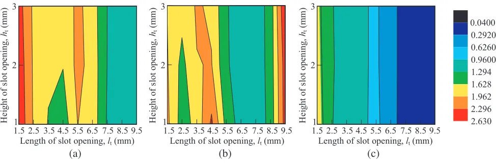
Based on the average thrust and cogging force characteristics, the ratios of thrust to cogging force were calculated and presented in the form of contour plot as shown in Fig. 8. The purpose of finding thrust to cogging force ratio is to identify the models with optimum thrust performance from each PM arrangement. High thrust ratio means that the model has high thrust with low cogging force while low thrust ratio indicates low thrust with high cogging force. Fig. 8 shows that the red region is for high ratio while blue region indicates the area for low ratio.
0.0400 0.2920 0.6260 0.9600 1.294 1.628 1.962 2.296 2.630 1.5 2.5 3.5 4.5 5.5 6.5 7.5 8.5 9.51
2 3
Length of slot opening, lt (mm)
H e ight of s lo t opening, ht (mm ) (c)
Length of slot opening, lt (mm)
1.5 2.5 3.5 4.5 5.5 6.5 7.5 8.5 9.5 1 2 3 H e ight of s lo t opening, ht (mm ) (b)
Length of slot opening, lt (mm)
1.5 2.5 3.5 4.5 5.5 6.5 7.5 8.5 9.51 2 3 H e ight of s lo t opening, ht (mm ) (a)
Figure 8. Ratio of average thrust,Fave to cogging force,Fcog; (a) radial, (b) axial, (c) Halbach.
Compared to radial and Halbach models, the thrust ratioFave: Fcog characteristics of axial models do not change uniformly as the length of slot openinglt and height of slot openinght are varied. These
characteristics can be seen in Fig. 8(b). In a certain value of the length of slot opening lt, the values
of thrust ratio for the different heights of slot opening, ht, differ significantly. This can be seen from
the models with lt= 1.5 mm,lt= 2.5 mm and lt= 4.5 mm. Similar to radial model, the highest range
of thrust ratio is indicated by the red region between 2.2960 and 2.6300 where the model with the highest thrust ratio has the thrust ratio of 2.6262. The model is axial withlt= 9.5 mm andht= 3 mm.
Meanwhile, the models withlt= 6.5 mm andlt= 7.5 mm fall under the region of low thrust ratio range
which is 0.9600 to 1.2940. Specifically, the axial model with the lowest thrust ratio is the model with
lt= 9.5 mm andlt= 4.5 mm with the thrust ratio of 1.0807.
Based on the Halbach average thrustFaveand cogging forceFcogcharacteristics discussed previously, it is shown that the average thrust of Halbach array decreased as the length of slot openinglt increased
ratio Fave: Fcog of Halbach models decreased as the length of slot opening lt increased. On the other
hand, the thrust ratio does not affect much by the variation of the height of slot opening,ht. Fig. 8(c)
shows the thrust ratioFave: Fcog contour plot for the Halbach models where it is shown that the highest thrust ratioFave: Fcog produced by the Halbach models is significantly lower than both radial and axial models in which the range of highest thrust ratio falls between 1.628 and 1.962. Similarly, the lowest thrust ratio Fave: Fcog is also low which is in the range of 0.0400 to 0.2920. The highest thrust ratio
Fave: Fcog of the Halbach produced by the model with lt = 1.5 mm and ht = 1 mm is at the ratio of
1.8439. Meanwhile, the Halbach model with lt = 9.5 mm and ht = 2 mm has the lowest thrust ratio Fave: Fcog, which is 0.0364.
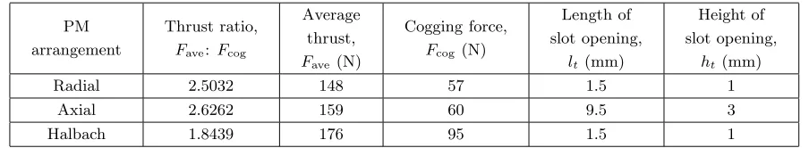
Table 5 shows the comparison of maximum thrust ratios produced by the models from these PM arrangements. From Table 5, it can be summarized that axial model has the highest thrust ratio which is 2.6262 with average thrustFave of 159 N and cogging force Fcog of 60 N. Radial model has a thrust ratio lower than axial model but higher than Halbach model which is 2.5032. The radial model has the average thrustFave of 148 N and cogging forceFcog of 57 N. Halbach model has the lowest thrust ratio which is 1.8439 with average thrust Fave of 176 N and cogging force Fcog of 95 N. Based on the thrust ratio, it is shown that, though Halbach model produced the highest average thrust Fave, the cogging force Fcog was also high hence resulted in low thrust ratio.
Table 5. Maximum thrust ratio for different PM arrangement.
PM arrangement
Thrust ratio, Fave: Fcog
Average thrust, Fave (N)
Cogging force, Fcog (N)
Length of slot opening,
lt (mm)
Height of slot opening,
ht (mm)
Radial 2.5032 148 57 1.5 1
Axial 2.6262 159 60 9.5 3
Halbach 1.8439 176 95 1.5 1
5. CONCLUSION
A PMLSM is designed in this paper. The design of PMLSM consists of two parts. The first part is to vary the PM arrangement, and the second part is to vary the stator slot opening parameters. There are three different PM arrangements which are radial, axial and Halbach models while the two parameters of the stator slot opening are the length of stator slot opening lt and the height of stator slot opening ht. For each PM arrangement, the length of stator slot openingltand the height of stator slot opening ht were set to their minimum values which are 1.5 mm and 1 mm, respectively. The values of the length
of stator slot openingltand the slot opening heighthtare then increased by 1 mm until they reach their
respective limit values. All the models designed were simulated by using FEM software, and the results obtained were compared and evaluated. There are three performances evaluated in this paper which are average thrust, cogging force and thrust ratio. These performance evaluations are used to determine the models with the optimum performances. Based on average thrust and cogging force characteristics, the ratio between these two performances is determined. Radial model withlt= 1.5 mm andht= 1 mm
has the highest thrust ratio,Fave: Fcog, which is 2.5032, and the highest thrust ratio,Fave: Fcog, of axial model is lt = 9.5 mm and ht = 3 mm which is 2.6262. Meanwhile, with the ratio of 1.8439, Halbach
model with lt = 1.5 mm and ht = 1 mm produced the highest thrust ratio, Fave: Fcog. However, as
the thrust F is considered as the main factor in evaluating PMLSM performances, the Halbach model with lt= 1.5 mm and ht= 1 mm has been chosen as the best final model. This model has the highest
average thrust, Fave, which is 176 N.
ACKNOWLEDGMENT
REFERENCES
1. Pakdelian, S., Y. Deshpande, and H. A. Toliyat, “An electric machine integrated with trans-rotary magnetic gear,” 2012 IEEE Energy Conversion Congress and Exposition (ECCE), 3356– 3362, Raleigh, NC, 2012.
2. Brando, G., A. Dannier, A. Del Pizzo, and L. P. Di Noia, “Electric steering for aircraft nose landing gears using axial-flux permanent-magnet motors,”2016 XXII International Conference on Electrical Machines (ICEM), 761–767, Lausanne, 2016.
3. Varaticeanu, B. D. and P. Minciunescu, “Modelling and analysis of dual-sided coreless linear synchronous motor,” Rev. Roum. Sci. Tech., Electrotech Net Energy, 2, Bucarest, 2014.
4. Oshima, S., S. Tahara, and K. Tagawa, “Thrust and thrust ripple of linear reluctance motor compared to permanent linear synchronous motor,” 15th International Conference on Electrical Machine and Systems (ICEMS), 1–4, 2012.
5. He, Q. and X. Bao, “Reducing cogging torque in permanent-magnet synchronous motors by auxiliary teeth method,” 2016 IEEE 11th Conference on Industrial Electronics and Applications (ICIEA), 1488–1495, Hefei, 2016.
6. Friswell, M. I., Dynamics of Rotating Machines, 228, Cambridge University Press, 2010.
7. Tzou, H. and T. Fukuda, Precision Sensors, Actuators and Systems, 75, Springer Science and Business Media, 2012.
8. Li, B., J. Zhao, X. Liu, Y. Guo, H. Hu, and J. Li, “Detent force reduction of an arc-linear permanent-magnet synchronous motor by using compensation windings,” IEEE Transactions on Industrial Electronics, Vol. 64, No. 4, 3001–3011, 2017.
9. Patel, A. N., “Influence of stator teeth shaping on cogging torque of radial flux permanent magnet brushless DC motor,” 2016 Biennial International Conference on Power and Energy Systems: Towards Sustainable Energy (PESTSE), 1–4, 2016.
10. Gieras, J. F. and Z. J. Piech, Linear Synchronous Motor-Transportation and Automation Systems, CRC Press, Boca Raton, Florida, 2000.
11. Azhar, F., H. Wakiwaka, K. Tashiro, and M. Nirei, “Design and performance index comparison of the permanent magnet linear motor,”Progress In Electromagnetics Research M, Vol. 43, 101–108, 2015.
12. Mohd Nasir, N. A., F. A. Abdul Shukor, R. N. F. K. Raja Othman, H. Wakiwaka, and K. Tashiro, “Design of permanent magnet linear synchronous motor stator to improve magnetic flux density profile toward high thrust density performance,” Mohamed Ali M., Wahid H., Mohd Subha N., Sahlan S., Md. Yunus M., Wahap A. (eds.),Modeling, Design and Simulation of Systems, AsiaSim 2017, Communications in Computer and Information Science, Vol. 751, Springer, Singapore, 2017. 13. Ling, Z., J. Ji, J. Wang, and W. Zhao, “Design optimization and test of a radially magnetized magnetic screw with discretized PMs,” IEEE Trans. on Industrial Electronics, No. 99, 1-1, 2017. 14. Shi, W., C. Xiao, Y. Lei, B. Yu, F. Wu, and P. Zheng, “Optimization on thrust ripple of an
axial-flux permanent-magnet linear synchronous machine,” 2011 International Conference on Electrical Machines and Systems, 1–6, Beijing, 2011.
15. Shahosseini, I. and K. Najafi, “Cylindrical halbach magnet array for electromagnetic vibration energy harvesters,”2015 28th IEEE International Conference on Micro Electro Mechanical Systems (MEMS), 1051–1054, Estoril, 2015.
16. Koo, M. M., J. Y. Choi, H. J. Shin, and J. M. Kim, “No-load analysis of PMLSM with halbach array and PM overhang based on three-dimensional analytical method,” IEEE Transactions on Applied Superconductivity, Vol. 26, No. 4, 1–5, 2016.