AGARWAL, MONAM. Infrastructure and Methods for High level Architectural Exploration for Graphics. (Under the direction of Dr. Gregory Byrd)
The work done in this thesis is divided into two categories. The first is the development of a
feasible infrastructure for fast and reasonably accurate studies of the complex scenarios of
interactions within an SoC. This infrastructure includes a simulator that has an abstract core,
along with models of the last level cache and cache controller, the interconnection network,
and memory. It is built using the SystemC TLM2.0 framework and is aimed to be abstract
and accurate. It is flexible and easy for experimentation, and helps to capture the functional
and performance characteristics of a system at an architectural level. The model is developed
and correlated against a product level cycle-accurate simulator for various parameters. In this
work, this scalable model is used to specifically mimic and study the behavior of graphics
interacting with the system.
The second focus is the characterization of graphics traffic captured outside of the graphics
core at the interface of the core and the rest of the SoC. This characterization is based on
finding interesting patterns in the traces captured. It is a kind of offline infrastructure
developed, that gives useful insights and when used along with the developed high level
model, aids in the process of finding and experimenting with graphics related optimizations
involving the last level cache.
Hence, this work addresses the development of a feasible high level abstracted model
i.e. a simulator as well as offline processing methods that can be used to study architectural
optimizations with a special focus on the integrated GPU scenario. It is observed that the
© Copyright 2016 by Monam Agarwal
by
Monam Agarwal
A Thesis submitted to the Graduate Faculty of North Carolina State University
in partial fulfillment of the requirements for the degree of
Master of Science
Computer Engineering
Raleigh, North Carolina
2016
APPROVED BY:
_______________________________ _______________________________
Dr. Gregory Byrd Dr. Huiyang Zhou
Committee Chair
DEDICATION
BIOGRAPHY
Monam Agarwal was born in November 1990 in Bijnor, India. She received her Bachelor’s
degree from Delhi College of Engineering, Delhi University in 2012 in the field of
Electronics and Communication engineering.
After completing her under graduation, she held position of Systems Engineer in the
In-process Electrical Checks Department in BrahMos Aerospace Pvt. Ltd, a joint venture of the
DRDO, India from 2012 to 2014. Currently she is a graduate student in the Department of
Computer Engineering at North Carolina State University. Her fields of interest lie in
Computer architecture, Performance modeling and analysis of complex System-on-Chip
ACKNOWLEDGMENTS
I would begin by expressing my gratitude to my advisor, Dr. Gregory Byrd, Associate
Department Head, Department of Electrical and Computer Engineering, for helping and
advising me, and giving useful suggestions and insights throughout the course of the thesis.
The successful completion of this work would not have been possible without his
encouragement and belief in my capabilities.
I am extremely grateful to the PDG Architecture team at Intel, Bangalore, my mentor Mr.
Saurabh Tiwari, CPU Performance Architect, Intel and the entire team as a lot of work on the
thesis was carried out during the course of my internship with this team. I am thankful to my
mentor for his valuable time and extremely useful technical sessions and advice and technical
help at various points in the project, for ramping me up on very fundamental and useful
concepts and helping me improve my skills throughout during the course of the work.
I am thankful to my family, my parents and my sister for always giving me moral support
and encouragement to be able to accomplish and achieve goals in life and hence also to be
able to complete this work successfully.
I am also grateful to my friends, Mansi, Lakshay, Manish, Sidhant, Sabir, Srijit who have
been my support all through my graduate school and played an important part for me
keeping up with the difficult times I faced during the course of my graduate studies and
TABLE OF CONTENTS
1 Introduction ... 1
1.1 Integrated vs. Standalone Graphics ... 1
1.2 Simulation of Integrated Graphics ... 4
1.3 Contributions ... 6
2 SystemC TLM 2.0 Simulation Framework ... 8
2.1 Use of SystemC TLM2.0 ... 8
2.2 Timing Model ... 9
2.3 Non-Blocking Interface ... 10
2.4 Transaction Packets ... 10
2.5 Scalability ... 11
2.6 Lumped Delays ... 11
2.7 Tracking, Crediting and Arbitration ... 11
2.7.1 Static Crediting ... 14
2.8 Statistics Collection and Parameters ... 15
3 The High-Level Uncore model Architecture ... 16
3.1 Injector/Graphics Core ... 17
3.1.1 Requests Tracking Table (Core) ... 18
3.1.2 Address Match Logic ... 19
3.2 The Interconnect: Core Arbiter ... 20
3.2.1 Multi-Socket ... 20
3.2.2 Arbiter Logic ... 21
3.2.3 Signal and Data Queues ... 22
3.2.4 Hash Logic ... 22
3.2.5 Credits and Delays ... 22
3.3 Last Level Cache and Cache Controller ... 23
3.3.1 The Last Level Cache ... 23
3.3.2 Replacement Policy ... 24
3.3.3 Cache Controller ... 25
3.4 Cache Controller Arbiter Interconnect ... 26
3.5 Memory Controller ... 27
3.6 Flows and Protocols Modeled ... 28
3.7 Synthetic Scenario Generation Capability and Synthetic Validation Flows ... 28
3.8 Launching Workload studies, Statistics Rollup, Debug Infrastructure ... 31
4 Golden Reference Model vs. the HL_uncore ... 32
4.1 The Ring Interconnect ... 33
4.2 The Last Level Cache and Cache Controller ... 33
4.4 Abstraction Choices of Hl_uncore with respect to the Reference Model ... 35
4.4.1 Abstraction Choice 1: Modeling of Ring Interconnect ... 35
4.4.2 Abstraction Choice 2: Simplification of Cache Controller Flows ... 36
4.4.3 Abstraction Choice 3: Lumped Delays ... 36
5 Correlation Studies and Results ... 37
5.1 Workloads ... 37
5.2 SoC Configuration for Experiments ... 38
5.3 Simulation Speed Comparison ... 40
5.4 Code Base Comparison ... 41
5.5 Correlation on Cache Associativity Study ... 41
5.5.1 Description ... 41
5.5.2 Discussion on Trends and Correlation ... 42
5.6 Correlation on Cache Size Study ... 46
6 Studies using HL_uncore Model ... 48
6.1 Memory Latency ... 48
6.2 Buffer Sizing ... 49
6.3 Cache Hits As a function of Time ... 53
7 Trace Characterization ... 56
7.1 Type of Requests Distribution ... 57
7.1.2 Results & Inferences ... 57
7.2 Data Footprint in Cache ... 58
7.2.1 Methodology ... 58
7.2.2 Results and Inferences ... 59
7.3 Stream Detection ... 60
7.3.1 Methodology ... 60
7.3.2 Results and Inferences ... 61
7.4 Cache Policy Studies based on Trace Characterization Results ... 62
7.4.1 Unique Addresses Accessed ... 62
7.4.2 Reuse Number Profiling ... 63
7.4.3 Cache Replacement Policy Experiment with HL_uncore based on Reuse Number 66 7.4.4 Reuse Distance ... 69
8 Conclusion and Future Work ... 73
LIST OF TABLES
Table 3.1 Synthetic Scenario Generation Flows ... 29
Table 5.1 Base SoC Configuration Details ... 39
Table 5.2 Code Base Comparison ... 41
Table 5.3 Difference in Hit Rates for Associativity = 8, Baseline LRU Policy ... 45
Table 5.4 Difference in Hit rates for Cache Sizes 1, 2, 4 MB ... 47
Table 7.1 Stream detection results ... 61
LIST OF FIGURES
Figure 1.1 Integrated Graphics Block Level Diagram ... 2
Figure 1.2 External Graphics Block Diagram... 3
Figure 1.3 CPU GPU Interaction ... 4
Figure 1.4 Overview of the Work ... 7
Figure 2.1 TLM Timing Models and their Implementation Mechanisms [3]... 9
Figure 2.2 Types of Crediting Protocols ... 13
Figure 3.1 Workload Flow for Graphics Simulation ... 16
Figure 3.2 Hl_Uncore High level Diagram ... 17
Figure 3.3 Detailed Architecture of Core Arbiter ... 18
Figure 3.4 Detailed Architecture of Core Arbiter Interconnect ... 20
Figure 3.5 Arbiter between Injector cores and Cache Controllers ... 21
Figure 3.6 Detailed LLC & Cache Controller Architecture ... 23
Figure 3.7 Detailed Cache Controller Arbiter Architecture ... 27
Figure 4.1 The Real Uncore Architecture [7] ... 32
Figure 4.2 The High level Core-LLC Interaction [9] ... 34
Figure 5.1 Simulation Speed Comparison ... 40
Figure 5.2 Trend for Varying Associativity- Baseline LRU ... 43
Figure 5.3 Trend for Varying Associativity- Vulnerable Fill ... 44
Figure 5.4 Trend for Varying Cache Size ... 46
Figure 6.1 Performance Evaluation for varying latencies ... 49
Figure 6.3 Speed Up/Performance Improvement for RTT Size=64 vs 32 ... 50
Figure 6.4 RTT (Size 64 vs. 32) Occupancy vs. Simulation Cycles for angry birds ... 51
Figure 6.5 RTT (Size 64 vs. 32) Occupancy vs. Simulation Cycles for Sandra ... 52
Figure 6.6 RTT (Size 64 vs. 32) Occupancy vs. Simulation Cycles for boshcluster ... 53
Figure 6.7 Cache Hits as a function of Time, angry birds workload ... 53
Figure 6.8 Cache Hits as a function of Time, race stars workload ... 54
Figure 6.9 Cache Hits as a function of Time, dead trigger2 workload ... 54
Figure 7.1 Pattern of Workload Traces ... 56
Figure 7.2 Opcode Distribution ... 58
Figure 7.3 LLC Data Footprint ... 59
Figure 7.4 Stream Detector Implementation ... 60
Figure 7.5 Percentage of Unique Addresses in Different workload traces ... 62
Figure 7.6 Reuse Number: Sandra ... 63
Figure 7.7 Reuse Number: real racing ... 64
Figure 7.8 Reuse Number: race stars ... 64
Figure 7.9 Reuse Number: asphalt8 ... 64
Figure 7.10 Reuse Number: cut_the_rope2 ... 65
Figure 7.11 Reuse Number: dead trigger ... 65
Figure 7.12 Normalized Hit Rates for various LRU configurations, Cache size = 4 MB ... 67
Figure 7.13 Normalized Hit Rates for various LRU configurations, Cache size = 1 MB ... 68
Figure 7.14 Reuse Distance Implementation ... 69
Figure 7.16 Reuse Distance: dead trigger2 ... 71
Figure 7.17 Reuse Distance: Sandra ... 71
1
Introduction
For many years, trends in high performance computing, guided by Moore’s Law, have
progressively led to the development of complex heterogeneous systems. Designs have been
able to accommodate increased complexity and optimizations due to the availability of
increased number of transistors on a single chip. It has led to increased circuit level
parallelism and integration of subsystems on the same die.
The trend of the GPU being integrated with CPU on the same die is the result of this
phenomenon. Today, graphics forms an integral part of many computing systems. The
increasing complexity, resolution and realism of game animation require highly specialized
processing engines to obtain high performance for graphics rendering. The CPU solely
cannot be relied for providing such high end performance. Hence specialized GPU
accelerators form an integral part in many systems today. The CPU-GPU system can have
mainly two configurations. The first one is the Integrated Graphics scenario. Intel and AMD
design such integrated systems, with Intel’s Sandy Bridge and AMD’s APU being two of the
first integrated CPU-GPU designs in the market. The second is the standalone graphics card
technology such as that produced by NVidia.
1.1
Integrated vs. Standalone Graphics
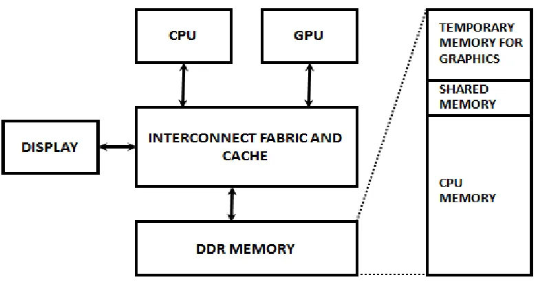
In the case of integrated graphics as shown in Figure 1.1, the graphics accelerator is
integrated within the same die as the CPU. It shares the last level cache, interconnect and the
system agent, consisting of the memory controller and the IO. The Double Data Rate (DDR)
DRAM memory in the case of integrated graphics has broadly three divisions. First is the
temporary or stolen memory that is used exclusively by graphics for storing intermediate
values. Second is the CPU memory that belongs totally to the cores, and forms the largest
buffer for commands issued from the host (CPU cores) to the device (GPU) and outputs for
the Display.
Figure 1.1 Integrated Graphics Block Level Diagram
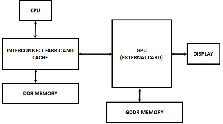
In contrast, in the case of standalone Graphics as shown in Figure 1.2, the CPU and the GPU
have separate DDRs. The host has a driver that connects through an IO bus such as PCIe.
The driver running on host programs the system-DMA to transfer data from host memory to
graphics card memory.
In a modern SoC, the cores are integrated with on-die last level caches, in addition to the
high level caches in the individual cores. To further reduce memory latency, the memory
controller is also brought onto the die. Hence the Graphics processor that is present on the die
alongside the CPU cores can take advantage of the on-die LLC for catering to its increased
bandwidth requirements, as GPUs are data intensive processing units.
The efficient utilization of on-die caching of integrated graphics traffic is a field of active
research. There are various existing cache policies that cater to the scenario of the CPU cores
optimization techniques is still open and being studied. Such studies requires fast and
efficient simulation infrastructure.
1.2
Simulation of Integrated Graphics
Conventionally, pre-silicon graphics simulation is done using a cycle-accurate simulator. The
game workloads are run on an older generation of silicon, over the underlying DX or
OpenGL API, where the driver underneath has instrumentation to capture the workload
traces[1]. These traces consist of two types of information: the command sequence and the
data describing the surfaces that refer to two-dimensional geometrical objects in context of
graphics, stored in memory. These trace files are fed to the graphics simulator.
Two kinds of scenarios can be simulated. In the first case, it is assumed that while the
graphics engine is active, the CPU cores are not in active mode. In other words, after doing
the relevant physics, the CPU cores are not in execution mode for any of the benchmarks
until the GPU executes a particular workload, as shown in Figure 1.3. The second case is the
mix of workloads relevant to both the CPU cores and the GPU fed at the same time, i.e. both
processing units are in active mode simultaneously. Both scenarios need thorough analysis to
derive a good performance from the SoC.
Figure 1.3 CPU GPU Interaction
Hence a robust simulation methodology and infrastructure needs to be developed even before
analyzing the above system for improvement and optimization. It is imperative that the
architectural design is validated and studied for optimizations and tradeoffs well within time
in the design flow. The duration spent on such studies should be minimal but at the same
time accurate to be able to reach well-informed design decisions to minimize issues in
post-silicon. Some of the issues revolving around Graphics simulation and its analysis are as
i) Stale workloads: The workload traces extracted are not updated, as they are obtained by running workloads on silicon that is at least a generation older than
the design for which the simulation is being carried out. Due to various software
and hardware architectural changes and driver optimizations
generation-over-generation, the traces collected are hence not very accurate. However, ideally it
should not make a very big difference in terms of performance.
ii) Simulation speed and Flexibility: The simulation models being cycle-accurate and modeled to the last level of detail in terms of microarchitecture are very slow.
It takes days for a particular job to complete and results to appear. Also, very
accurate and detailed models have less flexibility for lot of experimentation based
on architectural parameters for studying optimizations and other architectural
improvements.
iii) Large workloads: The workload traces that are obtained constitute gigabytes of data that is extremely hard to run in the compute farm that is distributed across the
globe, as these workloads need to be copied from one compute farm to another. It
further aggravates the problem of time-consuming simulation.
iv) Characterization of Graphics traffic to SoC: A lot of work has been done and is still being done for studying the 3D Graphics workloads and their
characterization based on their behavior inside the graphics engine. However,
characterization of traffic at the interface of the graphics and the SoC that has
filtered localities and very limited information is a field that needs to be explored
further.
v) SoC level Cache Optimizations for Graphics: As explained above, the optimization of caching for graphics at a SoC level is an area for exploration, in
1.3
Contributions
The work presented in this document focuses on three of the issues described above:
specifically, ii, iv and v.
First, a high level abstraction model is built using the SystemC TLM 2.0 framework for
simulation of a SoC at an abstract level, mainly used for architecture level analysis. The
model developed is fast, scalable, flexible to changes, easy to work with, and reasonably
accurate for carrying out a variety of function- and performance-based studies and analyses.
The second contribution is the characterization of the graphics traffic captured at the
interface of the SoC and the graphics core to understand the nature of the traffic at the SoC
and get an insight into the kind of caching optimizations that can be experimented with using
these results.
Third, using these two different kinds of infrastructure, studies have been carried out to
explore the avenues of optimizations in the caching policies for possibly improving the
performance of the system.
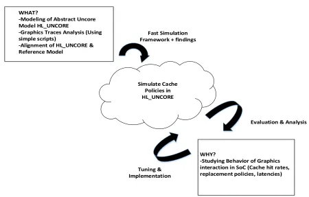
WHAT?
-Modeling of Abstract Uncore Model HL_UNCORE
-Graphics Traces Analysis (Using simple scripts)
-Alignment of HL_UNCORE & Reference Model
Simulate Cache Policies in HL_UNCORE
WHY?
-Studying Behavior of Graphics interaction in SoC (Cache hit rates, replacement policies, latencies) Fast Simulation
Framework + findings
Evaluation & Analysis
Tuning & Implementation
2
SystemC TLM 2.0 Simulation Framework
The Uncore is a term used to describe the section of a SoC that is not part of the processing
core/cores. The High level abstraction model of the uncore developed in this work is
developed in the SystemC Transactional Level Modeling (TLM) 2.0 framework. SystemC is
an open source library built on top of C++ that adds the capability of describing hardware at
various levels of detail. TLM is a high level of abstraction and helps in the modeling of
communication between various functional modules. In this case, TLM2.0 is used to describe
hardware at the SoC component level. Various sources [2],[3],[4],[5] have described the
modules and implementation mechanisms in SystemC TLM2.0 framework. The mechanisms
and constructs used in this work are described in the following sections.
2.1
Use of SystemC TLM2.0
The main reason for selecting SystemC TLM2.0 is its availability as an open source standard.
It is a single, unified, design and verification language that is used to express architectural
attributes and system level features in the form of C++ classes. SystemC enables modeling of
system architecture at a very highly abstracted level that is much faster than the pin- and
cycle-accurate RTL (Register Transfer Level) implementation. TLM 2.0 standard, integrated
with SystemC, gives the advantage of interoperability. TLM framework on top of core
SystemC modules allows easy exchange of these modules/IPs among different companies, or
within the same company among different teams. Apart from the basic communication
protocol, it provides the flexibility to customize the protocol of communication between
2.2
Timing Model
TLM2.0 provides two types of modeling methodologies with respect to timing: the Loosely
Timed (LT) and the Approximately Timed (AT) models, illustrated in Figure 2.1.
Figure 2.1 TLM Timing Models and their Implementation Mechanisms [3]
The model developed in this work is an approximately timed (AT) model presenting a high
level abstraction of a very detailed product level simulator. It is a cycle-count accurate model
and contains a notion of lumped timing that can be used for first-order performance analysis.
The model makes use of sockets, generic payloads, modified phases and a non-blocking
interface where each process is synchronized with the SystemC scheduler and runs in
2.3
Non-Blocking Interface
There are two types of processes in SystemC: methods and threads. A thread, once spawned,
executes until it is killed; however, it can be suspended by adding appropriate wait
statements. A method, on the other hand, cannot have wait statement but is sensitive to
particular events in the system, i.e. it executes only on the occurrence of mentioned events in
its sensitivity list.
The blocking transport methodology uses a thread for maintaining communication between
modules. After forwarding a request to another module, it waits for a specified amount of
time (the delay that tries to simulate the latency of issuing a request from one module to
another at a very highly abstracted level) and then returns to execution for proceeding with
the next requests. Such an implementation eliminates the need of buffering and crediting.
However, for modeling more complex and real scenarios, where there is a need to model
buffering of requests to imply a real sense of latency, a method is required. This is the basis
of the non-blocking transport implementation mechanism.
2.4
Transaction Packets
The data, command and acknowledgement content between modules is modeled as packets
that are communicated through ports and exports following a certain protocol. The
information packet is termed as a generic payload in TLM2.0 and can contain information of
the address, command and data, along with some other pre-defined fields. There is flexibility
of adding extensions, which means that additional information pertaining to the data packet
can be appended to the main information packet. This capability is used extensively in the
modeling of our system and enables detailed specification and easy modeling of complex
2.5
Scalability
Injector is a term used to define an abstracted core model that is used to inject inputs to the
system. The model developed for this thesis can scale from a single injector to multiple
injectors, although the focus is working with a single injector simulating a graphics core. The
model can be scaled to have multiple slices of the last level cache, and also have multiple
channels of memory. The connectivity for such scalability is achieved through the use of the
multi socket feature of TLM 2.0.
The multi-socket is used both ways, with the initiator to allow multiple targets and with the
target to ensure connectivity with many initiators. This feature provides ease and flexibility
in the building of a scalable system.
2.6
Lumped Delays
The model developed is an approximately timed model that uses lumped delays to have a
notion of time and latency. It means that it is a count accurate model and not a
cycle-accurate one, not defining the behavior and state after each and every cycle.
Having a notion of delays also helps in keeping the model deterministic. The functioning is
simple. To model the latency consumed by a transaction, it is pushed into a buffer and is
configured to stay in the buffer for the required latency, after which it is popped out of the
buffer. Such delay blocks are configurable and can be used for modeling different values of
delay as required by the experimentation.
2.7
Tracking, Crediting and Arbitration
Three concepts make an inherent part of the system modeling - the tracking of events
(transactions/requests), crediting flows between modules, and arbitration in the scenario of
The tracking of each transaction is essential in the system in various modules. The basic
interface protocol of TLM2.0 is customized to maintain system-specific phases.
Many STL containers from the C++ library are used to model the various architectural
components of the system. Vectors, lists and deques are used as per the requirement and
functionality of the particular structure to be modeled. For tracking structures in the injectors,
the cache controllers and the memory controller, vectors are used. The requests are buffered
up in the deque structures for implementing the FIFO functionality.
Simple arbitration is maintained for selecting among multiple injectors for injecting new
requests and for sending read and write requests to memory from the multiple cache
controllers. Arbitration modules with arbitration logic, appropriate delays, and storage
buffers thus form an integral part of the system ensuring scalability and efficient
communication of transactions between modules.
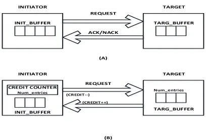
Another very important concept is that of crediting that is essential to maintain accuracy in
tracking, preventing overflow of buffers and loss of requests in the system unaccounted.
Crediting is maintained at the interface between any two modules, both in the forward and
INITIATOR TARGET
TARGET INITIATOR
REQUEST
REQUEST ACK/NACK
INIT_BUFFER TARG_BUFFER
INIT_BUFFER TARG_BUFFER
CREDIT COUNTER Num_entries
(CREDIT--)
(CREDIT++)
Num_entries CREDITING PROTOCOLS
(A)
(B)
Figure 2.2 Types of Crediting Protocols
The protocol shown in Figure 2.2 (A)is a simple request and response acknowledge protocol,
in that the initiator keeps sending a request to the target irrespective of the target buffer size
(it has no knowledge of the target buffer size) and receipt of as many NACKs until it finally
receives an ACK. With the protocol depicted in (B), a new request is sent from the initiator
to the target only if the target has a buffer entry free to accommodate the incoming request.
The tracking of free entries is done through the credit counter in the initiator. It implies that
the initiator has to keep information about the maximum available buffer entries in the target
and keep track of the free entries at a particular instant in the system, decrementing the
counter when a new request is sent and incrementing it when the request is processed further
and the target buffer entry is freed. The request is buffered in the initiator buffer itself until
there are free entries available. It seems that maintaining additional logic for crediting in (B)
time, since the new requests from initiator are still being sent every cycle and NACKs are
being received every cycle until an ACK is received, it increases the interconnect traffic
significantly, and is responsible for a lot of bandwidth and power consumption. It also
increases simulation time because the number of events to be processed increases. Hence it is
a good choice to have a simulation model with crediting flows even if the actual hardware
uses the ACK-NACK protocol.
In this model, the credit counters are combined with delays in every module to avoid race
conditions on these counters. Static crediting is used in this model as described in the next
section.
2.7.1 Static Crediting
In the static crediting protocol, multiple sources in the initiator share a common buffer in the
destination. This buffer in the destination is divided statically into as many numbers of parts
as the sources and each source is allowed to use only those many entries in the destination
buffer. The downside of using such a system is that it may lead to wastage of destination
buffer space in the case if one of the sources do not use all the entries allocated to it, while
the other source needs more entries than allotted but is unable to use them. In such cases an
alternate mechanism for efficiently sharing the destination buffer among sources dynamically
2.8
Statistics Collection and Parameters
The model developed can be used for analysis for a wide variety of configurations. Various
knobs are provided for configuring parameters to study the effect of each on the behavior of
the system. For example, some of the knobs used are to vary the size of the LLC, its
associativity, the memory configuration, the number of injectors, or number of cache
controllers.
The model is developed with very detailed counting statistics at every level to account for
quantitative analysis of performance pertaining to cache hit and miss rates, the bandwidth
and latency of requests, and other metrics. Histogram statistics are also supported, which
3
The High-Level Uncore model Architecture
This section describes the details of the high level uncore architecture model developed in
this work. It is an approximately timed scalable model with a detailed cache, cache
controller, and interconnect. The injector core is a simplistic model that contains abstracted
architectural details and is used to inject traffic captured at the core to uncore interface as
shown in Figure 3.1.
Figure 3.1 Workload Flow for Graphics Simulation
It shows that the transactions that have been captured at the interface of the GPU simulator
and the SoC detailed cycle level simulator are injected through a developed high level
injector to the high level abstraction model HL_uncore developed in this work. The model is
configurable for a multiple number of injectors, cache blocks and memory channels.
Figure 3.2 shows the high level view of the model, consisting of various modules and the
interfaces between them. Various abstraction choices have been made for maintaining
modeling and simulation flexibility and simplicity. New and more enhanced features can be
readily added, and new modules can be introduced to take advantage of the modularity of the
3.1
Injector/Graphics Core
This injector represents Graphics IP in the system. It is modeled protocol-accurate but
without any micro-architecture details. We do model the queuing of requests in this injector
as it is important to capture the latency and throughput limitations of the real system.
The model of a single core consists of an injector that injects new requests to the last level
cache and memory based on the arbitration policy and availability of credits.
3.1.1 Requests Tracking Table (Core)
The architecture includes a requests tracking table that is a major structure keeping a log of
active transactions in the system and their current status. Each request injected into the
system finds an entry in this table, along with a master transaction created for the same,
based on the availability of credits in the arbiter connected to the core and the size of the
Requests Tracking table. This table has 32 entries and each entry has a unique ID. Each entry
has various fields, corresponding to a particular request, i.e. its transaction, the opcode,
address and data associated with it, and various flags indicating the current status of the
request.
3.1.2 Address Match Logic
An Address match logic is implemented in the injector that ensures that two requests to the
same memory address are not active simultaneously in the system. It is implemented as a
mechanism that iterates over the current log of requests in the Requests Tracking table. If a
match is found, the new request is stalled until the previous request to the same address is
completed. This makes sure that two requests to the same address are not outstanding from
the same injector as it is difficult to maintain ordering/coherence between them. Order should
be maintained strictly from the injector point of view potentially in write after write scenarios
etc. Hence the injector must issue second request to the same address after completion of the
first one.
3.1.3 Delays and Credits
Appropriate delay blocks are configured in the core to simulate lumped delays on the data
flow path (data received from memory as the result of a read request, or data sent to memory
as the result of write request) and the commands path. The delays have been configured with
approximate values of cycle delays on these paths to maintain a notion of approximate timing
and determinism in the various flows. Static credit counters for signals and data have been
3.2
The Interconnect: Core Arbiter
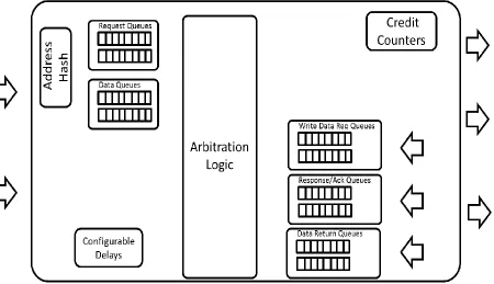
Interconnect between the core and the uncore as shown in Figure 3.4 has been modeled as an
arbiter block and is one of the major abstraction choices selected in the model. It is a
structure that is responsible for the coherent flow of requests between the cores and the cache
controllers
Figure 3.4 Detailed Architecture of Core Arbiter Interconnect
3.2.1 Multi-Socket
The arbiter is modeled to have a multi-socket interface; it is essentially a single connection
port, but has the provision for connecting to multiple input ports and multiple output ports. It
is an excellent feature in the TLM2.0 framework and has been used to model the arbiter to
add flexibility while scaling the model, i.e. extending the model to have multiple cores and
3.2.2 Arbiter Logic
The arbitration logic is hierarchical. It ensures that in one cycle, there is no clash of requests
from multiple injector cores to one particular cache controller. The arbiter logic for the
forward flow of data or requests is shown in Figure 3.5 and works as follows:
i) In every cycle, each cache controller ID is picked up, and for each particular ID,
the core queues are searched for any ready requests to be sent to that particular
cache controller
Figure 3.5 Arbiter between Injector cores and Cache Controllers
ii) A core counter is maintained that contains the ID of the core injector that is at the
highest priority in the round robin logic for that particular cycle. The head of the
core queue is searched. If it contains a request for that particular cache slice, the
request is forwarded. If it does not contain a request for that cache controller, the
counter is incremented and the next core queue is searched.
iii) Once a request is found for a particular cache controller, the next cache slice ID is
picked up and the core queues are searched in a round robin fashion, starting from
the core pointed by the current value of the core counter, for a ready request for
iv) The same arbiter logic is used to abstract the interconnect between the injector
and the cache controllers and the cache controllers and the memory
v) Resource contention is avoided by this policy, as only one out of many incoming
requests to the same destination is allowed in one cycle. Multiple requests can
progress to different destinations in a single cycle.
3.2.3 Signal and Data Queues
Separate queues are maintained for data packets (incoming requests) and for signals
(acknowledgement signals) both in the forward and in the backward paths. The separate
queues are used to model parallel paths for the flow of data and control signals in a single
cycle. Within the control signal flow as well, separate paths and storage buffers are
maintained for incoming control signals in the forward path and acknowledgment signals in
the backward path.
3.2.4 Hash Logic
The hashing logic is implemented in the arbiter to calculate the cache controller ID and the
slice ID within each cache. The implementation is based on a simplistic approach using the
incoming request address. Relevant high-entropy bits of the address are used to route the
requests to a particular cache block and slice. This logic is in place to ensure that all the Last
level cache slices are used optimally with no one cache slice is hot-spotted or under-used.
3.2.5 Credits and Delays
Static credits are maintained for all buffers in the arbiter to avoid overflow and resultant loss
of requests/data in the system. Configurable Delay blocks are configured on each path
3.3
Last Level Cache and Cache Controller
3.3.1 The Last Level Cache
The last level cache is a set-associative cache. Its capacity can be divided into blocks, each of
which has a separate cache controller block. Within each cache block, there is further
division in form of slices. Each slice has sets. Each set consists of the following fields: Tag,
Valid bit, MESI state, Snoop filtering bits corresponding to each request injector (core), and
the LRU counter for victimization and replacement. The cache is configurable for various
sizes and associativity, and it can be divided into the required number of blocks. The division
of the cache capacity into different blocks enables faster lookup and catering to more than
one request per cycle.
3.3.2 Replacement Policy
The Quad-age LRU policy [11] is implemented as the replacement policy for victim selection
and insertion of new lines into the cache. This policy is based on the fact that a particular
cache line in the cache can have 4 ages i.e. from 0 to 3; with 0 denoting the least recently
used (LRU) line and 3 being the most recently used (MRU) line. According to the age of the
line, as well as the type of request, the policy replaces a victim and installs a new line into the
cache.
3.3.2.1 Victim Selection
When a set is accessed and a line has to be replaced from the set, the first LRU counter with
zero value is searched from the left i.e. way-0, way-1 and so on. This line is selected as the
victim for eviction to make space for the incoming line.
3.3.2.2 Insertion
The insertion age of the cache line is fixed at 2. It ensures that once the line is installed in the
cache, it has the opportunity to be used for a few times and produce few hits before it itself
becomes the victim. For all the request types, i.e. the read request and read ownership
opcodes and the write request and write back request opcodes, the insertion age is fixed at 2.
3.3.2.3 LRU Update Logic
The update of the LRU counter is Quad-age based. A per-opcode age table is maintained that
gives the value of the LRU counter if there is a hit to that particular line. A line becomes less
vulnerable to eviction and saturates at the maximum value of 3 (indicating LRU) if it causes
many hits after its installation. To ensure that a zero is always found while searching from
present. However if zero is not found, then the minimum age among the ways in that set is
subtracted from all the ages in the set.
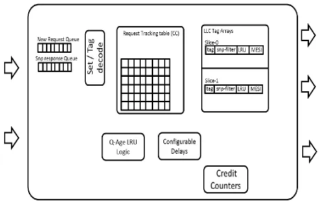
3.3.3 Cache Controller
3.3.3.1 Requests Tracking Table (RTT- Cache Controller)
This is the most important structure in the cache controller and has the cycle by cycle
updated status of each active request in the cache. The Requests Tracking table is similar to
the one that is present in the core injector and contains the data, address and status
corresponding to each active transaction. In this model, the RTT has 32 entries for 32 unique
transactions and gets updated after every action performed in the core, LLC or memory
unless that request is completed. It acts as a temporary buffer for dirty victimized cache line
data, unless the data is written back to the memory. Hence it implements the Fill before Spill
refill technique, i.e. the cache line can be filled with new data, instead of waiting for the
victimized cache line data to be written back to the memory first.
For the completion of cache hit requests and memory requests that are ready, there are
independent mechanisms that work every cycle to progress the first available hit and memory
request in the simulation.
3.3.3.2 Delays and Credits
Various lumped delays have been modeled in the data and control flow. A constant delay of
n cycles has been configured for the lookup delay of the cache; this is includes the latency of
indexing to the required set, matching the tags, and deciding a hit or a miss. In case of a miss,
latency of selection of a victim is also included in this delay. The lookup delay is
encountered every time there is a lookup to the cache, whether it’s a new request or a victim
signals are configured to one clock cycle, in both forward and backward paths. New requests
are accepted by the cache controller based on occupancy of the Requests Tracking table, or
else the request wait in the New Requests Queue that is searched every cycle for a ready
request that can be a valid Request Table entry. The credits indicating the occupancy of the
new requests queue are sent back to the arbiter every cycle.
3.3.3.3 Set-Match Reject Logic
The set match reject logic is implemented to ensure that no more than one request to a
particular set in a particular LLC block is active in the system. This check is implemented
while the requests are still in the new requests queue and are about to make an entry in the
Requests Tracking Table. If two requests work on the same set in the LLC simultaneously, it
can result in incorrect update of the LRU counters for that particular set, leading to the
selection of incorrect cache lines for victimization.
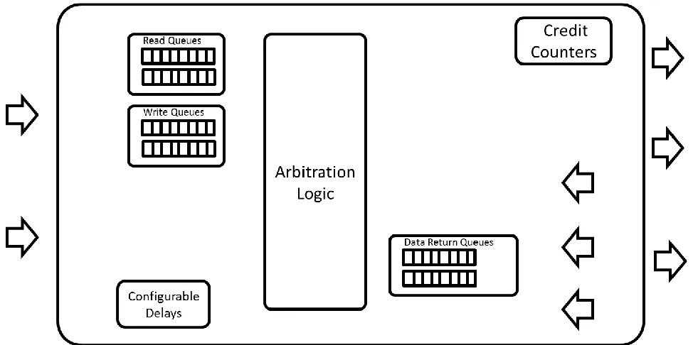
3.4
Cache Controller Arbiter Interconnect
This interconnect enables communication between the Last level cache blocks and the
memory controller, consisting of one or more memory channels. The interconnect consists of
multiple sockets as the input and output ports to ensure flexibility in scaling the architecture
model to increase the number of cache controller blocks or the number of memory channels.
It has a similar arbitration logic as the core arbiter interconnect. It consists of separate queues
for data and request queues and also separate read and write queues for each memory
channel. The logic takes care of the fact that not more than one request can be sent from
Figure 3.7 Detailed Cache Controller Arbiter Architecture
3.5
Memory Controller
An existing model of the memory controller has been integrated with the currently modeled
high level system of the uncore. The memory controller has configurable memory channels
and a memory address decode logic. The memory channels have a scheduler modeled; based
on the read mode or the write mode, the scheduler handles requests stored in the read and the
write queue. The reads are given priority over writes unless a threshold value of writes occur
in the write queue, after which the mode changes from read to write and write requests are
3.6
Flows and Protocols Modeled
The current model supports six kinds of request opcode flows:
i) Data Read Request
ii) Data Write Request
iii) Read for Ownership Request
iv) Write Back Request from upper level cache
v) Uncacheable Write Request
The MESI protocol is modeled to support the multi core scenarios. However the snooping
flow is simplistic, modeling only the backward invalidate flow.
Static crediting model has been implemented to take care of buffer occupancy at a particular
instant in time.
3.7
Synthetic Scenario Generation Capability and Synthetic Validation
Flows
The injection methodology used in this work gives flexibility for synthetic traffic generation
and can be used to inject real traffic traces extracted from running application workloads.
Synthetic traffic generation is achieved by providing various kinds of information such as the
beginning addresses of the requests, the type of request (i.e. the opcodes), and what kind of
traffic - streaming, random, etc. needs to be generated. A mixture of requests of various types
can also be specified, with a given percent distribution of each type.
The injection methodology uses the SystemC Verification library utilities to create
randomized requests. Such blocks of information are defined as tasks that are mapped to
nodes. One task can be mapped to one or more nodes. Nodes are in turn mapped to actual
task mapped to a single hardware component or a number of tasks with complex
dependencies mapped to various nodes.
The dependencies are defined in terms of a graph that specifies the initial nodes and the
triggering nodes and mapping of the tasks to the nodes. Such synthetic traffic generation is
very helpful in initial stages of the model development where specific flows need to be
checked for, studied and analyzed. Apart from the synthetically generated task scenarios,
entire workload traces can also be defined as tasks and mapped to nodes. This gives a great
deal of flexibility in defining the inputs to the model. In this work, this method of synthetic
generation of traces is used for various studies, validation of various data and control flows,
data collection and analysis. Five flows were implemented in the current model. These are
the Data Read Flow, the Data Write Flow, and Read for Ownership and Write Back flows
and the Uncacheable writes. Each flow requires individual validation for its correct
functionality before the model can be injected with real large workload traces. A few of the
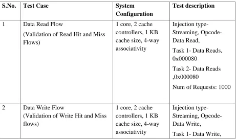
generated test cases are shown in Table 3.1 .
Table 3.1 Synthetic Scenario Generation Flows
S.No. Test Case System
Configuration
Test description
1 Data Read Flow
(Validation of Read Hit and Miss Flows)
1 core, 2 cache controllers, 1 KB cache size, 4-way associativity
Injection type-Streaming, Opcode- Data Read,
Task 1- Data Reads, 0x000080
Task 2- Data Reads ,0x000080
Num of Requests: 1000
2 Data Write Flow
(Validation of Write Hit and Miss flows)
1 core, 2 cache controllers, 1 KB cache size, 4-way associativity
Injection type-Streaming, Opcode- Data Write,
0x000080
Task 2- Data Write ,0x000080
Num of Requests: 1000
3 Mix of Opcodes (Read & Write)
(Validation of mixed requests and Arbitration logic using multiple cores for injection)
i) 1 core, 2 cache controllers, 1 KB cache size, 4-way associativity
ii) 2 cores, 2 cache controllers, 1 KB cache
size; 4-way
Injection type-Streaming, Opcode- Data Read, Data Write
Task 1- Data Read (50%) Data Write (50%),
Start Address : 0x000080
Num of Requests: 1000
4 Dirty Victimization Flow 1 core, 2 cache
controllers, 1 KB cache size, 4-way associativity
Injection type-Streaming
Task 1- Data Read Address 0x000080 (100 requests)
Task 2- Write Back Address
0x000080 (100 requests)
Task 3- Data write Address
0x0000c0 (100 request)
3.8
Launching Workload studies, Statistics Rollup, Debug Infrastructure
The Hl_uncore model supports detailed debug infrastructure constituting of cycle by cycle
state of each module, the buffers in every module and the transaction status tracking tables.
The model has the provision to be debugged using a particular flow, following it to the level
of a single transaction, seeing its state at every cycle until it is active in the system.
The model also has basic support for debugging using an internal tool that uses visualization
techniques to track down every transaction, when a new transaction was created, when it was
killed/released and its entire life duration event by event.
Job files were created using python scripts for injecting graphics workloads in various
configurations and for data collection. The job files were then launched on Net batch for
parallel processing and fast completion of the jobs. This was very helpful as a wide variety of
studies could be done with many workloads and multiple configurations.
The model supports a lot of relevant knobs to configure the system according to the needs of
the studies undertaken. The knob infrastructure adds flexibility to the system; the source code
need not be touched every time there is a change in the configuration of the model. The
knobs can be modified accordingly.
The statistics collected from every run of the model with different configuration is collected
using scripts to collect only relevant statistics for that particular study. This selective rollup is
4
Golden Reference Model vs. the HL_uncore
The Golden reference model used in this work is a Product Simulator that mimics the real
architecture of the uncore[9]. It includes the Last level cache, cache controller, the
interconnect and the System agent with the IO, memory controller and other units. The
reference model is a very detailed, cycle accurate model of the uncore architecture and
implements all minute as well as major features of the product architecture. The actual
architectural model is shown in Figure 4.1.
4.1
The Ring Interconnect
The ring-based interconnect is used for communication between the cores, the last level
caches, the graphics core and the system agent (which contains the memory controller and
interfaces to many input and output devices). It is composed of four sub-rings, namely:
i) Request Ring
ii) 32-byte Data Ring
iii) Snoop request Ring
iv) Acknowledge Ring
The four separate rings provide parallel paths for communication. All the different agents
listed above are present on the ring as stops. The ring maintains coherency and order between
the multiple requests to different agents and helps optimize latency in the communication.
4.2
The Last Level Cache and Cache Controller
The last level cache is a high bandwidth cache that is shared among the processor cores and
the graphics. It is an inclusive multi-bank LLC with 64B cache lines and 16-way
associativity. The LLC size is scalable according to the number of processing cores, and both
cores and caches run at the same frequency.
The cache box or the cache controller is the interface block within the LLC slice that
Figure 4.2 The High level Core-LLC Interaction [9]
4.3
Coherency and Ordering
The ring does not maintain the order and coherency of various requests from different agents.
Ordering is only maintained by the respective sender of the request. On the ring, the
transactions flow in parallel and are out of order. MESI protocol is implemented for
maintaining coherency. Snoop filtering is used in the LLC, i.e., every cache line has Core
4.4
Abstraction Choices of Hl_uncore with respect to the Reference Model
The model developed in this work is a high level one that does not capture the architectural
details of the real system to the lowest level. Hence it is called an abstracted model. It is a
flexible and scalable model that can be enhanced. More features can be added to it as needed
for performing architecture studies. However, some features of the Golden Reference Model
have been abstracted to facilitate fast but accurate simulation of the scenario being studied:
execution by the graphics core only. The remainder of this section describes those
abstraction choices in detail.
4.4.1 Abstraction Choice 1: Modeling of Ring Interconnect
The ring interconnect in the real architecture is abstracted in the high-level model. It is a
reasonable abstraction choice for a one-core model where only the graphics core is simulated,
which is the focus of this work. Functionally, it is a reasonable choice for multicore as well,
as a simple arbitration scheme using a round robin policy is modeled for a fair distribution of
requests from different sources to different destinations. The subrings in the real architecture
are approximated by the separately maintained buffers for data, request and
acknowledgement signals.
In the scenario of standalone graphics simulation, the stress is on catering to the required
bandwidth because the bandwidth demands are enormous for a graphics processor. The
bandwidth requirements of the graphics core are met by the banking of the LLC into different
blocks and slices. However the interconnect model can be approximated as for the graphics
scenario, the latencies are not very crucial and the latency for individual requests brought in
by the transactions on the ring do not introduce serious problems in the model with respect to
However in terms of performance, the correlation between the two models, purely based on
the effect of the abstraction of ring, will be closer for a one-core system as compared to a
multi-core system.
4.4.2 Abstraction Choice 2: Simplification of Cache Controller Flows
Another abstraction choice that has been made is the simplification of the request flows that
are supported in the model. The flows are simple though detail-oriented and have enough
description to simulate a real flow with reasonable accuracy. However, the scenarios in a
particular flow that are rare but add a great deal of complexity have been omitted in the
implementation with a negligible impact on the accuracy of the model as explained by the
correlation data presented in the later sections.
4.4.3 Abstraction Choice 3: Lumped Delays
The developed model is not a cycle-accurate one, and does not give the details and status of
each and every modeled hardware component at the end of every cycle. However a
reasonably accurate notion of time and determinism is maintained in the model appropriate to
high level modeling, through the use of lumped delays. For example, in order to model the
lookup delay in the cache, a lumped delay is configured to n cycles to mimic the average case
in the real architecture. It doesn’t update the status of the system after each cycle, but gives
an updated state after the configured delay. Also the values of such lumped delays used in the
model are configurable and can be modified as per a particular requirement of system
5
Correlation Studies and Results
The section presents the results of the correlation studies performed for the developed
HL_uncore model with respect to the existing product level simulator. The functional
correlation has been done to establish confidence in the developed model so that it can be
used reliably for experimentation and the results can be directly indicative of the actual
trends that can be expected from the detailed simulation models. This correlation studies has
been undertaken based on varying the parameters of the LLC size and associativity.
The developed model has also been compared with the baseline reference based on the
simulation speed and code base to indicate the ease and flexibility of using this model over
the detailed one for analyzing first-level functional and performance trends.
The workloads and the configurations used for analysis are described in the next section.
5.1
Workloads
Fifteen workload traces were selected for different kinds of studies. These traces are captured
at the interface of the core and the uncore while running the game benchmarks on silicon. All
the simulations carried out in this work are trace-driven because it is faster as compared to
the execution based simulation. The traces are without timestamps and consist of the type of
request and the memory addresses only as shown in Figure 7.1. The accuracy could be
affected if the timestamps are not taken into account as the timestamps make the bandwidth
demand more realistic. However addition of timestamps would further increase the size of
these traces. At this level of architectural studies, this abstraction has therefore been found to
The workloads are-
i) Sandra
ii) Boshcluster
iii) Daimlerhulf
iv) Unigine-heaven
v) Unigine-valley
vi) Angry_birds
vii) Basemarkx
viii) Clashclans
ix) Cut_the_rope2
x) Dead_trigger2
xi) Race_stars
xii) T-rex
xiii) Manhattan
xiv) Real_racing
xv) Asphalt8
5.2
SoC Configuration for Experiments
The SoC configuration used for carrying out correlation studies as well as standalone
Table 5.1 Base SoC Configuration Details
Parameter Value
Number of Injectors 1
Number of Cache Controllers 2
LLC Size 1,2,4 MB
LLC Associativity 4,8,16 -ways
5.3
Simulation Speed Comparison
This section presents results of comparison of the simulation speed of the developed model
with respect to the baseline reference model. The Simulation speed up achieved by the
Hl_uncore model is plotted with respect to the baseline model as shown in Figure 5.1. The
maximum speed ups achieved are in the range of 18x for few workload traces like
basemarkx, boshcluster, manhattan etc. The average speedup achieved is around 9x.
Impressive simulation speed-up over the baseline reference simulator enables HL_uncore
simulator to be used for early architecture evaluation studies that require multiple iterations
of simulations to evaluate wide-variety of architecture options.
angry_bi
rds asphalt8
basemar kx
boshclus ter
clashcla ns
daimlerh ulf
manhatt an
race_sta rs
real_raci
ng sandra trex SPEED UP 3.49 8.52 17.87 17.73 7.06 4.52 17.07 9.13 8.97 0.17 8.86
0 2 4 6 8 10 12 14 16 18 20
SPEED UP
5.4
Code Base Comparison
The code base comparison as shown in Table 5.2 indicates that the Hl_uncore model has
much less code and fewer modules to be handled.
Table 5.2 Code Base Comparison
Parameter Value (Base Model/Hl_uncore)
Lines of Source Code ~6x
Number of Files/Modules ~3x
It has multiple advantages over a detailed product simulator-
It is apt for easy experimentation as compared to the baseline product simulator model
because it has greater flexibility to modify code and implement newer architecture proposals
with less effort.
Another advantage is that less code results in fewer bugs in the simulation model.
5.5
Correlation on Cache Associativity Study
In this section, the cache hit trend is studied by varying associativity, keeping cache size
constant and using two variations of the LRU policy.
5.5.1 Description
One is the baseline policy with the install age or LRU counter value equal to 2 and
particular cache line. The other policy is that of vulnerable fill in which the cache line install
age is 0, i.e. initially it is vulnerable to victimization, but the age counter increases if hits are
seen to that particular cache line.
5.5.2 Discussion on Trends and Correlation
The trend of associativity for the baseline Quad-age LRU policy (Figure 5.2) for both the
models shows that the cache hit rate increases, and conflict misses decrease with increasing
associativity. However the Vulnerable fill LRU policy (Figure 5.3) shows a reverse trend of
associativity, i.e. the cache hit rates decrease with the increasing associativity. In a vulnerable
fill policy, a cache line is installed in the cache at an age of 0, i.e. most susceptible to getting
victimized. The results from the graph show reversed trends of hit rates with associativity.
This is because in this policy, only a particular way keeps getting victimized while rest of the
ways in a particular set remains unused most of the times. Hence for increasing associativity,
the number of sets that remain unused, it being equivalent to wasted cache capacity and the
Figure 5.3 Trend for Varying Associativity- Vulnerable Fill
The plots of normalized cache hit rates with respect to varying associativity for different
LRU policies show matching trends between the developed model and the baseline model for
0.100 0.200 0.300 0.400 0.500 0.600 0.700 0.800 0.900 1.000 as so c_ 4 as so c_ 8 as so c_ 1 6 as so c_ 4 as so c_ 8 as so c_ 1 6 as so c_ 4 as so c_ 8 as so c_ 1 6 as so c_ 4 as so c_ 8 as so c_ 1 6 as so c_ 4 as so c_ 8 as so c_ 1 6 as so c_ 4 as so c_ 8 as so c_ 1 6 as so c_ 4 as so c_ 8 as so c_ 1 6 as so c_ 4 as so c_ 8 as so c_ 1 6 as so c_ 4 as so c_ 8 as so c_ 1 6 as so c_ 4 as so c_ 8 as so c_ 1 6 as so c_ 4 as so c_ 8 as so c_ 1 6
manhattan race_stars realracing t_rex sandra daimlerhulf angry_birds basemarkx clashclans cut_the_rope2 dead_trigger
Normalised Hit Rate-Reference Model
0.100 0.200 0.300 0.400 0.500 0.600 0.700 0.800 0.900 1.000 as so c_ 4 as so c_ 8 as so c_ 1 6 as so c_ 4 as so c_ 8 as so c_ 1 6 as so c_ 4 as so c_ 8 as so c_ 1 6 as so c_ 4 as so c_ 8 as so c_ 1 6 as so c_ 4 as so c_ 8 as so c_ 1 6 as so c_ 4 as so c_ 8 as so c_ 1 6 as so c_ 4 as so c_ 8 as so c_ 1 6 as so c_ 4 as so c_ 8 as so c_ 1 6 as so c_ 4 as so c_ 8 as so c_ 1 6 as so c_ 4 as so c_ 8 as so c_ 1 6 as so c_ 4 as so c_ 8 as so c_ 1 6
manhattan race_stars realracing t_rex sandra daimlerhulf angry_birds basemarkx clashclans cut_the_rope2 dead_trigger
various workloads. Two contrasting cache replacement policies have been studied as shown
in Figure 5.2, and Figure 5.3. They show the opposite trends of cache hit rates with
increasing associativity.
Table 5.3 shows the hit rate differences between the 2 models for different workloads shows
that the maximum misalignment between the hit rates is for the dead trigger trace at 3.8%
Table 5.3 Difference in Hit Rates for Associativity = 8, Baseline LRU Policy
Workload Hit Rate Difference (Hl_uncore vs Reference Model)
Manhattan -0.5 %
race stars -1.6 %
real racing -1.6 %
t_rex -2.1 %
Sandra 0.0 %
daimlerhulf -0.9 %
angry birds -0.7 %
asphalt8 -0.6 %
basemarkx -0.3 %
clashclans -1.4 %
cut_the_rope2 -3.3 %
![Figure 4.1 The Real Uncore Architecture [7]](https://thumb-us.123doks.com/thumbv2/123dok_us/1516679.1185834/47.612.91.364.282.595/figure-the-real-uncore-architecture.webp)
