ISSN (Online) : 2319 - 8753
ISSN (Print) : 2347 - 6710
I
nternationalJ
ournal ofI
nnovativeR
esearch inS
cience,E
ngineering andT
echnologyAn ISO 3297: 2007 Certified Organization, Volume 2, Special Issue 1, December 2013
Proceedings of International Conference on Energy and Environment-2013 (ICEE 2013)
On 12th to 14th December Organized by
Department of Civil Engineering and Mechanical Engineering of Rajiv Gandhi Institute of Technology, Kottayam, Kerala, India
DESIGN, DEVELOPMENT AND TESTING OFINJECTOR
FORSUBSYSTEM DEVELOPMENT OF
SEMI CRYOGENIC ENGINE THRUST HAMBER
G Rohit1, M.Kanthasamy2, G.Remesh3, Dr.V.Narayanan4, Raju P Thomas5, NRV. Kartha6
LPSC, ISRO Thiruvananthapuram, 695003 India1,2,3,4,5,6
ABSTRACT
A Semi Cryogenic Engine is being developed to power the booster stages of India’s future launch
vehicles. Achieving the highest possible specific impulse for a particular propellant combination has always been a key factor for space launch systems.
Many of the current rocket engines work on toxic propellants combination like Monomethyl hydrazine (MMH), Nitrogen Tetroxide (N2O4), Unsymmetric Dimethly Hydrazine (UDMH) are difficult
to handle. Any failure using this propellant have catastrophic implications on environment. There is an increased thrust to explore environment friendly propellants.
Need for high thrust booster for increased payload requirement along with reliability and reusability have provided a new focus that is centered on using high density impulse (LOX/ISR) propellant combination working with oxidizer rich staged combustion (ORSC) cycle.
Various developmental activities have been taken up to gain expertise in design of thrust chamber injector, a critical component that largely determines the engine performance and main chamber life.
The goals of the effort described here are to establish an empirical knowledge base to provide a fundamental understanding of main chamber injectors and for verification of an injector design methodology for the ORSC cycle. This paper provides a summary of the status of injector developmental activities at LPSC, ISRO. The baseline Preburner and injector operating conditions and geometries are described. Injector performances in tests carried out are briefly discussed.
NOMENCLATURE
Mass flow rate
φ Spray cone angle
Cd Coefficient of discharge
Cn Coefficient of Non Uniformity
Abbreviation
GOX Gaseous Oxygen LOX Liquid Oxygen
ISR Isrosene (Refined Kerosene) MR Mixture Ratio
ELV Expendable launch vehicles RLV Reusable launch vehicles PB Preburner
SPB Special Preburner TC Thrust chamber CC Combustion Chamber
SEIH Single Element Injector Head SETC Single Element Thrust Chamber
1.INTRODUCTION
ISRO is developing a 2000kN Semi cryogenic engine for the use in ELV and RLV. This engine is deemed to work on oxidizer rich staged combustion cycle using LOX and ISR propellant combination at a chamber pressure of 18.0MPa and at an overall engine mixture ratio of 2.65. The engine is designed to operate from 60% to 105% of nominal thrust level.
The major subsystems of the engine are TC, PB, turbo pump, Thrust and mixture ratio control system, feed circuits and flow control components. Preburner generates oxidizer rich hot gas at high pressures to drive the turbine. The exhaust gas from the turbine is then injected into the thrust chamber.
The thrust chamber is the combustion device where the propellants are metered, injected, atomized, mixed and burned to generate hot gas (reaction products) which is accelerated and ejected at high velocity to impart thrust. A thrust chamber has three major parts an injector, combustion chamber and nozzle. Ignition in TC is initiated using hypergolic slug (mixture of TEA and TEB) contained in a module.
Various developmental activities have been taken up to gain expertise in design of thrust chamber injector, a critical component that largely determines the engine performance and main chamber life.
Generally the design of injector element is very empirical and largely depends on testing experience. Evaluation of injector performance at main engine level testing is costly and time consuming.
So in order to characterize injector element, an injector head with a single base element has been configured to work on oxidizer rich hot gas and ISR combination. The goal is to evaluate the performance at element level and generate a model to correlate its performance to main engine.
To feed the element with oxidizer rich hot gas a “Special” Preburner using GOX/Isrosene as
propellants has been designed and realized.
In addition to qualitatively characterizing the injector element by evaluating the performance parameters, a holistic approach has been chosen to evaluate the material compatibility (especially in contact with oxidizer rich hot gas), ignition characteristics (hypergolic slug is used as igniter), thermal parameters such as gas temperature and heat flux near the injector face and the chamber wall and combustion dynamic characteristics.
2.CONFIGURATION OF SINGLE ELEMENT INJECTOR HEAD
FIGURE 1. SEIH ASSEMBLY
2.1 Injector
In view of design considerations of main injector head, the injector is designed to as a coaxial swirl type element. Many engines with LOX/RP-1 combination use swirl type injector for their better atomization, mixing of propellants and uniform distribution of propellants.
Due to requirements of about 450kg/s and 170kg/s of oxidizer and fuel flow into combustion chamber of main engine, 469 elements are arranged in 12 rows in concentric rows in steps of 6 to meter and distribute the propellants across the CC for uniform combustion. The arrangement pattern of injector element is shown in Figure 2.
TC is basically configured with two types of injector elements – Nominal (base) and protruding element. The nominal injector elements are contrived to deliver oxidizer-rich gas through a long post with flow controlled with an orifice and fuel through 12 tangential holes arranged in 2 rows (each 6Nos.). The element is provided with 12mm recess length. These elements consists of the following three parts namely orifice, casing of post and bush, connected together by orbit welding. Fuel enters through bush part of the assembly.
Orifice is made of nickel based alloy to check for compatibility in oxygen rich medium at high temperature. The post and bush are made of steel. The injector element assembly is shown in Fig 2.
FIGURE 2. INJECTOR ELEMENT ASSEMBLY Water cooled chamber was conceived and realized for element characterization.
3. CONFIGURATION OF SPECIAL PRE BURNER
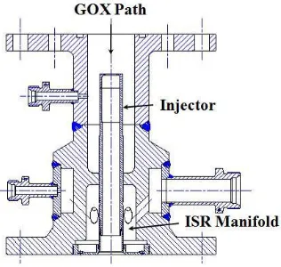
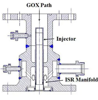
FIGURE 3. SPB ASSEMBLY
3.1 Injector
The challenge of injector design in PB is to configure an element which works at very high MR (210). The injector element is designed as a coaxial swirl type with its own primary combustion zone. In order to sustain the combustion, the element is configured such that primary combustion takes place at relatively lower MR and then additional GOX is fed to dilute the hot gas. The element has an ISR post and GOX sleeve. The injector element configuration is shown in Fig 4.
FIGURE 4. SPB INJECTOR ASSEMBLY
3.2 Injector Housing
The injector head is configured to provide uniform admission of both the propellants and easy accommodation of the injector element assembly. Injector housing consists of separate GOX and ISR manifolds through which the propellants enter the injector element.
FIGURE 5. SPB INJECTOR HOUSING
3.3 Chamber
SPB has two stages of chamber – intermediate and main. It is provided with intermediate chamber to have relatively smooth dynamic response. The intermediate chamber opens up into the main chamber for further mixing of hot oxidizer to attain temperature uniformity.
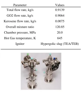
The chamber is made of Haynes 214 (nickel alloy) and is radiation cooled with a nozzle throat insert to carry out standalone tests. Specifications of the SPB are given the table below
TABLE 1. SPECIFICATIONS OF SPB
Parameter Values
Total flow rate, kg/s 0.9139
GO2 flow rate, kg/s 0.9064
Kerosene flow rate, kg/s 0.0075
Overall mixture ratio 120.85
Chamber pressure, MPa 20.0
Hot Gas temperature, K 645
Igniter Hypergolic slug (TEA/TEB)
FIGURE 6. REALIZED SPB ASSEMBLIES
4.OPERATING PARAMETER OF SEIH TEST
SEIH is designed to operate from 60% of flow rate to 105% through the injector. However the hardware is tested only to the flow conditions corresponding to 60% of the main TC due to the facility limitation.
TABLE 2. SPECIFICATIONS OF SEIH
Parameter Values
Total flow rate, kg/s 1.23
GO2 flow rate, kg/s 0.916
Kerosene flow rate, kg/s 0.314
Overall mixture ratio 2.65
Chamber pressure, MPa 18
5. COLD FLOW TESTS
Injector elements of both SPB and SEIH have been subjected to cold flow tests as acceptance criteria before they were used for hot tests. The cold flow tests are done at part, element and injector head level. The cold flow test fixtures are designed and realized for carrying out cold flow test of individual elements.
Objectives of cold flow test are
• Evaluation of pressure drop across the injector element.
• Measurement of spray cone angle.
• Coefficient of non uniformity.
•
Droplet size and its distribution.
FIGURE 7. INJECTOR ELEMENT
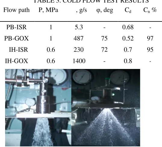
Cold flow tests are carried out at lab level with DM water as the working medium for all the flow cavities of the injector elements. Figure 7 and 8 show element and head level cold flow tests. Table 3 gives the details of parameters obtained during the cold flow test.
TABLE 3. COLD FLOW TEST RESULTS Flow path P, MPa , g/s φ, deg Cd Cn %
PB-ISR 1 5.3 - 0.68 -
PB-GOX 1 487 75 0.52 97
IH-ISR 0.6 230 72 0.7 95
IH-GOX 0.6 1400 - 0.8 -
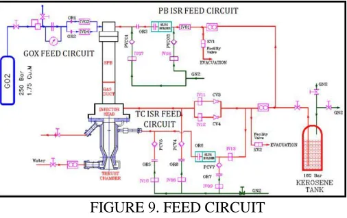
6.TEST ARTICLE CONFIGURATION AND FEED CIRCUIT
Test article is conceived to carry out the injector characterization hot test in pressure fed mode. Configuration consists of GOX feed system to SPB and Isrosene feed systems to SPB and SEIH.
Feed systems have valves and flow control devices to feed the propellants at the required pressure. It is designed for step mode operation to take care of ignition characteristics and to avoid hot start problems.
Hypergolic slug module (Tri-ethyl Aluminum/ Tri-ethyl Boron) installed in the ISR feed circuits serves as the ignition source. Both SPB and SETC ISR feed systems have separate igniters (hypergolic slug modules) installed in the line. Figure 9 shows the feed circuit of integrated testing of SEIH.
7. COLD FLOW TESTS AND FINALIZATION OF HOT TEST SEQUENCE
Various cold flow tests on GOX and Isrosene feed circuits of SPB and SETC has been carried out to assess the flow resistance of the fluid circuits, response time of various valves.
GOX lead combustion is adapted for both SPB and SETC. All the valves are sequenced open and close to avoid hot start and shut down transients.
FIGURE 9. FEED CIRCUIT
8.TEST RESULTS AND DISCUSSIONS Standalone test of SPB
Standalone tests of SPB are conducted to evaluate the performance of the hardware. Three tests were conducted at 60% de-rated condition – one 5s duration and two 20s.
A smooth ignition transient was achieved. Oscillations in the chamber pressure were within 2% of the nominal value.
8.1 Single element Integrated Thrust Chamber Tests
After standalone tests of SPB, the hardware is integrated with SEIH and water cooled CC and tested.
FIGURE 11. INTEGRATED TEST ARTICLE
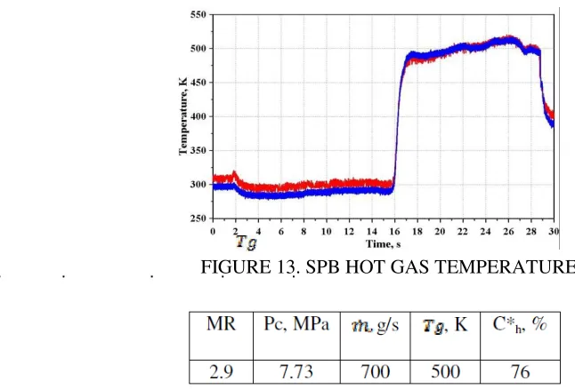
The test was carried at 55% condition. Figure 12 shows PB and TC pressure measurements along with the flow rates of propellants. Figure 13 shows the temperature of hot gas generated in PB.
FIGURE 13. SPB HOT GAS TEMPERATURES
The combustion efficiency achieved during the test is 76%. Oscillations were observed during the test duration. Pressure peak around 250Hz is noticed from the pressure measurement indicating buzzing in the combustion chamber.
FIGURE 14. FFT ANALYSIS OF CHAMBERPRESSURE
9.CONCLUSION
Tests have been conducted on SPB and SETC. The design of SPB and its injector has been validated as capable of providing oxidizer rich hot gas at very lean MR with smooth dynamic characteristics. Nickel based alloy have been proven as compatible in hot oxygen rich environment.
The injector has been tested up to 55% of rated condition. Combustion efficiencies up to 80% have been achieved and test results indicate a tendency of increasing combustion efficiency up to 90% when operated in nominal operating conditions. Further improvement of combustion efficiency is expected in multi element configuration due to better atomization and mixing.
Characteristics of buzzing were observed in the dynamic pressure measurements, which are caused by mechanical vibration of structure and propellant feed system resonances.
injector geometrical parameters will be modified and studied to improve the performance.
ACKNOWLEDGEMENT
This presented development activities is a team work where in various agencies have contributed. The authors thankfully acknowledge the contributions given by P Marudhachalam, S Varadharajan, K Kumar and team for realization of hardware. Dr T John Tharakan and team for cold flow tests. N Vinod Kumar and team for supply of hypergolic slug. Shri David Dasan, Shri Subramonian Pillai, Shri S K Govindarajan and their teams for facility establishment, instrumentation and operation activities during testing. Shri D Venkataraman and team for realizing control components. We also thank T. Madhu Kumar and team for their contribution and support as a core project team.
REFERENCES
[1] Patankar, S.V., 1980, Numerical Heat Transfer and Fluid Flow, Hemisphere, Washington, DC.
[2] Purohit, G.P., Donatelli, P.A., Dhir, V.K., and Driscoll, R.J., July 1996, Transient Thermal Modeling of ARC 5 lbf Bipropellant Thruster, AIAA-96-3304.
[3] Purohit, G.P., Donatelli, P.A., Ellison, J.R. and Dhir, V.K., January 2000, Parametric Examination of the Effect of Propellant Temperature and Pressure on Transient Thermal Response Of a Bipropellant Thruster, AIAA 2000- 107 1
[4] Incropera, F.P. and Dewitt, D.P., 1990, Introduction to Heat Transfer, John Wiley and Sons, New York.
[5] Gater, R.A., M.R. L’Ecuyer. “A Fundamental Investigation of the Phenomena that Characterize Liquid Film Cooling,” Jet Propulsion Center, TM-69-1, Jan, 1969.
[6] Bartz, D.R., “A simple Equation for Rapid Estimation of Rocket Nozzle Convective Heat Transfer Coefficients”, ARS Journal, Jan 1957, p 49.
[7] Stechman, R.C., “Film Cooling of Small Rocket Engines,” MIR #264, Aug 1968.
[8] Schoenman, L. and Block, P., “Application of Laminar Boundary Layer Heat Trnasfer Theroy to Low Thrust Rocket Nozzles”, AIAA Paper No. 67-447, July 1967.
[9] Parkinson, R.C. and Ziebland, H., "Heat Transfer in Rocket Engines", AGARDograph No. 148, 1971.
[10] David T Harrje, Liquid propellant rocket combustion instability, NASA SP-194.
[11] George P Sutton, Rocket Propulsion elements, Wiley India Pvt Ltd.
[12] Vigor Yang, Liquid Rocket Thrust Chambers: Aspects of modeling, analysis and design, Volume 200, AIAA 2004.