Volume 3, No. 3, May-June 2012
International Journal of Advanced Research in Computer Science
RESEARCH PAPER
Available Online at www.ijarcs.info
ISSN No. 0976-5697
Evolution of Object Oriented Analysis & Design in Software Engineering
Amit Kumar Shrivastava*
Research Scholar, Dept of CSE CMJ University Shillong (Meghalaya), India
Sanjiv Kumar Shriwastava
Principal, SBITM, Betul, Madhya Pradesh, India [email protected]
Rohit Sharma
Research Scholar, Dept of CSE CMJ University Shillong (Meghalaya), India
Abstract: In this paper Object Oriented Analysis, Object Oriented Design, Object Oriented and evolution of Object Oriented Analysis & Design is described. The Conventional methodologies like structured and Martin information engineering is explained. The importance of OOAD and evolution is aimed for this paper. The purpose, benefits, design of OOAD is explained. Comparison of popular OO languages and Programming object oriented concepts is also described in the paper, Case study of Banking is used to simplify the object oriented analysis & design. Process based studies also span multiple disciplines including, but not limited to, OO design procedural design/programming and weaving design. Studies of creativity have taken place in the less formally structured domains such as graphic design and industrial design rather than more structured software-engineering disciplines. The improving OO related training relies on understanding the cognitive skills and activities that are applied in practice when a designer translates his or her formal knowledge of the paradigm into working knowledge applied in a specific design situation using OOAD.
Keywords: Object Oriented Analysis, Object Oriented Design, Object Oriented, Evolution Object Oriented Analysis & Design
I. INTRODUCTION
The basic idea behind OOA is to reflect the problem domain, system’s responsibilities and user requirements by means of identifying and defining classes and their objects found in the specified domain. It focuses on what the system is supposed to do rather than how the system is to be built. OOD is concerned with the proper and effective structuring of a complex system. Using an OO notation at a higher level than the individual constructs of a programming language Object-oriented (OO) technologies (programming languages, tools, methods, and processes) are claimed to improve the quality of software product deliverables, to support reuse and reduce the effort of developing and maintaining the software product[1].
As object oriented analysis and design techniques become widely used, the demand on assessing the quality of object-oriented designs substantially increases. As with traditional analysis, the primary goal of object-oriented analysis is the development of an accurate and complete representation of the problem domain. Object-oriented analysis and design methods take full advantage of the object specialization hierarchy when it comes to modeling the objects in a system. When modeling system behavior, however, system analysts continue to rely on traditional tools such as state diagrams and dataflow diagrams. While such diagrams capture important aspects of the processes they model, they offer limited guidance as to the ways in which a process can be improved.
II. OBJECTORIENTEDANALYSIS(OOA)
Object Oriented Analysis is concerned with specifying system requirements and analysing the application domain. OOA is the process of converting the real-world problem into a model using objects and classes as the modeling constructs [2]. The objects identified from OOA are called semantic objects since they have meaning in the problem Domain. OOA is primarily concerned with the problem domain i.e. what the system should do, not how it should be accomplished Object Oriented Analysis (OOA)is concerned with developing requirements and specifications expressed as an object model (population of interacting objects) of a system, as opposed to the traditional data or functional views. Object-oriented analysis tries to identify the type of objects that map into elements of the application domain to be modeled. [3]
A. Benefits of OOA are:
a. Reuse Solution – by reusing already established design, system analysts get a head start on their problems. System analysts do not have to reinvent solutions for commonly repeating problems. In this way, system analysts can minimize their intellectual effort as well as time and cost.
b. Establish Common Terminology – from a solution
readability and understandability perspective, analysis patterns provide a common base vocabulary and a common viewpoint of the problem for system analysts.
c. Promote Modeling Quality – as promoting proven
entire stakeholders about the quality of the overall conceptual model. Particularly, system analysts get the benefit of learning from the experience of others. A preliminary study has highlighted the effectiveness of applying analysis patterns in helping the analyst identity missing classes, associations and aggregations.
B. The methods of OOA are:
a. Finding class and object – specifies how class and objects should be found. The first approach is given by starting with the application domain and identifying the classes and objects forming the basis of the entire application and, in the light of this, the systems responsibilities in this domain are analyzed.
b. Identifying structures – this is done in two
different ways, first the generalization structure, which captures the hierarchy among the identified classes. Second, the whole part structure, which is used to model how an object is part of another, and how objects are composed into larger categories.
c. Defined subject – this is done by portioning the
class and object model into larger units. Subjects are groups of class and object. The structure identified earlier can be used.
d. Defining attributes - This is done by identifying information and association for every instance. This involves identifying the attributes needed to characterize each object.
e. Defining services – defining the operations of the classes. This is done by identifying the object states and defining services fof accessing and altering that state
Some activities involved in OOA are Describe object dynamics in terms of constraints, conditions and effects [4], Examine related systems and locate existing software components for reuse, Provide a ‘first cut’ for the design of the system [5].
III. OBJECTORIENTEDDESIGN(OOD)
Object Oriented Design is concerned with implementing the requirements identified during OOA in the application domain. Object-oriented design transforms the analysis classes into a computerized model that belongs to the solution space Object Oriented Design (OOD) is concerned with developing object-oriented models of a software/system to implement the requirements identified during OOA.
Object-oriented Design is often touted as promoting software reuse [6]. Sometimes however the benefits of the object-oriented approach are overstated, and claims are made that features can be added to an object-oriented system without disturbing the existing implementation. The object-oriented software often needs to be restructured before it can be reused. While some software reuse techniques have focused at the code level, others have focused on design-level reuse. There are limitations on the reuse of code: it works best when the domain is narrow and well understood
and the underlying technology is very static. Sometimes the design of software is reusable even when the code is not. However, a major problem with design-level reuse is that there is no well-defined representation system for design. An important object-oriented technique for facilitate design-level reuse is an application framework. [7]. Good frameworks are usually the result of many design iterations and a lot of hard work involving structural changes [8, 9]. These changes may involve a single refactoring, or a series of related refactorings
A. Purpose of OOD
a. Reusability: Reusability is the process to which a
software module or component can be used in more than one computing program or software system. The goal of reusability guidelines is to reduce designing, coding, and testing, so that the total system will be understandable and ensures faster development of software applications[10][11][12]
b. Extensibility: Extensibility mentions the ability to add or change a function or data without changing the existing functions or data, so that the design will be free from unwanted side effects
c. Robustness: Robustness is the stability of software
applications in extreme situations that is, maximum load conditions. OMT model mentions that a method is robust if it does not fail even, if it receives improper parameters [13].
IV. OBJECTORIENTED(OO)
Object-Oriented technologies are becoming pervasive in many software development organizations. However, many methods, processes, tools, or notations are being used without thorough evaluation. An object is defined as a concept, abstraction, or thing with crisp boundaries and meaning for the problem at hand. Each object has its own state diagram. An event generated at one object could trigger state transitions of several other objects. The dynamic interaction between objects is through the use of the same event name at different locations in the dynamic model. This way, events are globally defined. The dynamic model does not have crisp boundaries as the object model has. The collection of state diagrams with globally used event names make it difficult to understand the dynamic behavior of a system. Objects include physical entities as well as concepts, such as trajectories, seating assignment, and payment schedules. All classes must make sense in the application domain; computer implementation constructs must be avoided. Classes often correspond to nouns. Searching for classes really is a search for objects. Every object belongs to some class. A class can have many instances or even just the one object found. Without being too selective.
development, easier maintenance for the designers and increased quality for the users. A designer runs a piece of design against a list of design heuristics that were build up through many years of design experience . Some terms associated with object oriented are given below:
a. Object: The term object was first formally applied in
the Simula language, and objects typically existed in Simula programs to simulate some aspect of reality [14]. An object has state, behavior, and identity; the structure and behavior of similar objects are defined in their common class; the terms instance and object are interchangeable.
b. Class: “A class represents a template for several
objects and describes how these objects are structured internally. Objects of the same class have the same definition both for their information structure” [15].
c. Inheritance: “Inheritance is the sharing of attributes and operations among classes based on a hierarchical relationship” [16].
d. Polymorphism: “Polymorphism means that the sender
of a stimulus does not need to know the receiving instance’s class. The receiving instance can belong to an arbitrary class” [15].
e. Abstraction: It means, to represent the essential feature without including the background explanation.
f. Encapsulation: “Encapsulation is the process of
hiding all of the details of an object that do not contribute to its essential characteristics” [15].
g. Aggregation: It is used to treat a collection of objects as a single object. For example, among other things, a car consists of tires and an engine. Note that the opposite of aggregation is decomposition.
h. Association: It can be viewed as a weak form of
aggregation or as a data-oriented relationship between two entities. For example, the following relationship models the concept that if there is a car, it must be associated with an owner.
Although design patterns are not strictly speaking an OO concept, they are covered here because of their increasing prevalence and acceptance within the OO community [17]. As such, design patterns are likely to be applied as part of the OO design process as studied by the methodology described in this paper. According to Alexander et al. [17][18], “Each pattern describes a problem which occurs over and over again in our environment, and then describes the core of the solution to that problem in such a way that you can use this solution a million times over, without doing it the same way twice.” Although this seminal work describes patterns in the context of building architecture, this description applies equally well to object-oriented software patterns, whose solutions are expressed in terms of objects and interfaces rather than walls and doors [19].
V. CONVENTIONALMETHODOLOGIES
A systems development methodology combines tools and techniques to guide the process of developing large- scale information systems. The evolution of modern methodologies began in the late 1960s with the development
of the concept of a systems development life cycle (SDLC). Dramatic increases in hardware performance and the adoption of high-level languages had enabled much larger and more complicated systems to be built. The SDLC attempted to bring order to the development process, which had outgrown the ad hoc project control methods of the day, by decomposing the process into discrete project phases with “frozen” deliverables- formal documents- that served as the input to the next phase. The systems development life cycle concept gave developers a measure of control, but provided little help in improving the productivity and quality of analysis and design per se. Beginning in the 1970s, structured methodologies were developed to promote more effective analysis and more stable and maintainable designs. Early structured methodologies were largely
process-oriented, with only a minor emphasis on modeling of entities and data.
A. Tools for Structured Methodologies:
a. Dataflow diagram (DFD) - Depicts processes (shown
as bubbles) and the flow of data between them (shown as directed arcs). DFDs are usually organized into a hierarchy of nested diagrams, where a bubble on one diagram maps to an entire diagram at the next lower level of detail.
b. Data-dictionary - Arepository of definitions for data elements, files, and processes. A precursor to the more comprehensive “encyclopedias.”
c. Entity-relationship diagram (ERD) - Depicts
real-world entities (people, places, things, concepts) and the relationships between them. Various notations are used, but usually entities are portrayed as boxes and relationships as arcs.
d. Hierarchy diagram - A simple diagram that shows a
top-to-bottom hierarchical decomposition of data files and data items (enclosed within boxes) connected by undirected arcs.
e. Mini-spec - A structured-English specification of the detailed procedural logic within a process; performs the same function as the traditional flowchart. A mini-spec is developed for each process at the lowest level of nesting in a set of DFDs.
f. State-transition diagram - Depicts the different
possible states of a system or system component, and the events or messages that cause transitions between the states.
g. Structure chart - Depicts the architecture of a system as a hierarchy of functions (boxes) arranged in a tree-like structure.
h. Information Engineering. In the late 1970s and early
1980s, planning and modeling of data began to take on a more central role in systems development, culminating in the development of data-oriented methodologies such as information engineering.
B. Tools for Martin Information Engineering:
b. Bubble chart - A low-level diagram used as an aide to normalization of relational tables. Shows attributes (depicted as bubbles) and the functional dependencies between them (depicted as directed arcs).
c. Dataflow Diagram (DFD) - Conforms to the
conventional notation and usage for dataflow diagrams (see the sidebar, "Tools for structured methodologies").
d. Data-Model Diagram - Depicts data entities (boxes)
and their relational connections (lines). Shows cardinality and whether the connections are optional or mandatory. Similar to the entity-relationship diagram.
e. Data-Structure Diagram - Shows data structures in a
format appropriate to the database management system to be used for implementation.
f. Encyclopedia - A more comprehensive version of the
data dictionary that serves as an integrated repository for modeling information from all development phases, including the enterprise model.
g. Enterprise Model - A model that defines, at a high
level, the functional areas of an organization and the relationships between them.
h. Entity-Process Matrix - Cross-references entities to
the processes that use them.
i. Process-Decomposition Diagram - A hierarchical
chart that shows the breakdown of processes into progressively increasing detail. Similar to the conventional tree diagram, except a particularly compact notation is used to fit many levels on one page.
j. Process-Dependency Diagram - Adiagram consisting
of processes (depicted by bubbles) and labeled arcs. It shows how each process depends on the prior execution other processes. Similar to a dataflow diagram, except conditional logic and flow of control is also depicted.
k. State-Transition Diagram- Conforms to the
conventional notation and usage for state-transition diagrams (see the sidebar, "Tools for structured methodologies").
VI. EVOLUTIONOFOBJECTORIENTED ANALYSISANDDESIGN(OOAD)
Object-oriented technology is gaining substantial interest as a beneficial paradigm for developing software applications. Several approaches have evolved to model OO designs. The Unified Modeling Language [20] is the result of the unification process of earlier OO models and notations. UML models capture the application static and dynamic aspects, but do not provide dynamic model execution or simulation. The Real-Time Object Oriented Modeling (ROOM) [21] was introduced to study the dynamic aspects of applications constructed as concurrently executing objects. ROOM design models support simulation of the application execution scenarios.
a. Any project in the world has the following phases: b. Planning
c. Analysis: system requirements are studied and structured
d. Design: recommended solution is converted into logical and then physical system specifications a) Logical design – all functional features of the system
chosen for development in analysis are described independently of any computer platform
b) Physical design – the logical specifications of the system from logical design are transformed into the technology-specific details from which all programming and system construction can be accomplished
e. Implementation f. Testing g. Maintenance
A. Object-Oriented Analysis and Design (OOAD):
a. Based on objects rather than data or processes b. Object: a structure encapsulating attributes and
behaviors of a real-world entity
c. Object class: a logical grouping of objects sharing the same attributes and behaviors
d. Inheritance: hierarchical arrangement of classes enable subclasses to inherit properties of superclasses
B. OOAD Project Phases:
a. Analysis
a) Requirement gathering, analysis, and modeling (Requirement Engineering)
b) Use Case Model find Uses Cases, Flow of Events, Activity Diagram)
c) Object Model
i. Find Classes & class relations,
ii. Object Interaction: Sequence & collaboration Diagram, State Machine Diagram,
d) Object to ER Mapping b. Design
a) Physical DB design b) Design elements
c) Design system Architecture
d) Design classes: Checking The Model, Combine Classes, Splitting Classes, Eliminate Classes
e) Design components f) GUI design
In the late 1980s, using object-oriented analysis (OOA) techniques in system analysis has received a great attention from the information systems (IS) groups and organizations [22]. The complete software life cycle spans from initial formulation of the problem, through analysis ,design, implementation, and testing of the software, followed by an operational phase during which maintenance and enhancement are performed The methodology has the following stages[23]:
b. System Design: The system designer makes high-level decisions about the overall architecture. During system design, the target system is organized into subsystems based on both the analysis structure and the proposed architecture. The system designer must decide what performance characteristics to optimize.
c. Object Design: The object designer builds a design
model bases on the analysis model but containing implementation details. The designer adds details to the design model in accordance with the strategy established during system design. The focus of object design is the data structures and algorithms needed to implement each class.
d. Implementation: The object classes and relationships
developed during object design are finally translated into a particular programming language, database, or hardware implementation. Programming should be a relatively minor and mechanical part of the development cycle, because all of the hard decisions should be made during design.
VII. DESIGNINGOBJECTORIENTEDANALYSIS ANDDESIGN(OOAD)
Different OOAD methodologies are defined like
Analysis is usually defined as a process of extracting and codifying user requirements and establishing an accurate model of the problem domain. Design, by contrast, is the process of mapping requirements to a system implementation that conforms to desired cost, performance, and quality parameters. While these two activities are conceptually distinct, in practice the line between analysis and design is frequently blurred. One of the frequently cited advantages of object orientation is that it provides a smoother translation between analysis and design models than do structured methodologies. It is true that no direct and obvious mapping exists between structured analysis and structured design
Object Oriented Design with Applications (OODA) by Booch [24], Object Oriented Analysis and Object Oriented Design (OOA/OOD) by Coad & Yourdon [25, 26], Object Oriented Analysis and Design (OOAD) by Martin & Odell [27], . Object Modeling Technique (OMT) by Rumbaugh, et al. [28], Object Oriented Systems Analysis (OOSA) by Shlaer & Mellor [29], Designing Object Oriented Software (DOOS) by Wirfs- Brock, et al. [30]
A. Object-Oriented Analysis Methodologies:
Object Oriented Analysis Activities involves Classes which Identify the classes which are part of the system. State which Identify the attributes that of each class. Behavior which Identify the operations or services needed for each class. Collaborations which Identify collaborations between classes.
As with traditional analysis, the primary goal of object-oriented analysis is the development of an accurate and complete representation of the problem domain. We conducted a literature search to identify well-documented, broadly representative OOA methodologies first published
in book form or as detailed articles in refereed journals from 1980 to 1990. The goal here is to provide a detailed comparison of representative methodologies at a single point in time, not a comprehensive review. The 00s methodology consists of a seven-step procedure:
a. Identify key Problem Domain Entities: Draw dataflow
diagrams and then designate objects that appear in process names as candidate entities.
b. Distinguish Between Active and Passive Entities:
Distinguish between entities whose operations are significant in terms of describing system requirements (active entities) versus those whose detailed operations can be deferred until design (passive). Construct an entity-relationship diagram (ERD).
c. Establish data flows between active Entities:
Construct the top-level (level 0) entity-dataflow diagram (EDFD). Designate each active entity as a process node and each passive entity as a dataflow or data store.
d. Decompose entities (or functions) into sub entities
and/or functions: This step is performed iteratively
together with steps 5 and 6. Consider each active entity in the top-level EDFD and determine whether it is composed of lower level entities. Also consider what each entity does and designate these operations as functions. For each of the sub entities identified, create a new EDFD and continue the decomposition process.
e. Check for new entities: At each stage of
decomposition, consider whether any new entities are implied by the new functions that have been introduced and add them to the appropriate EDFD, reorganizing EDFDs as necessary.
f. Group functions under new entities: Identify all the
functions performed by or on new entities. Change passive to active entities if necessary and reorganize EDFDs as appropriate.
g. Assign entities to appropriate domains: Assign each
entity to some application domain, and create a set of ERDs, one for each domain. Design is the process of mapping system requirements defined during analysis t o an abstract representation of a specific system-based implementation, meeting cost and performance constraints.
Another important benefit claimed for OOAD is improved communication among development team members, as well as between users and developers [31]. In this research, several field studies were conducted using developers’ timesheets, videotapes of meetings on design activities and semistructured interviews with developers.
VIII. BANKINGEXAMPLE
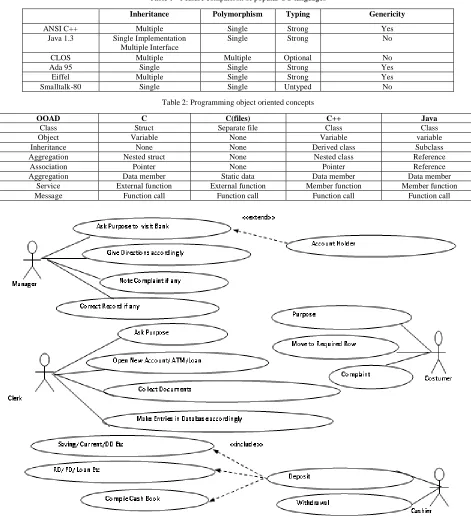
Here we use a Bank Activity System (BAS) for case diagram and activity diagram Fig 1 shows the UML Use Case diagram of BAS. The users or actors of the system and their characteristics are as follows:
Clerk is a person who is responsible for: a) Opening new account b) issuing token to the customer.
Cashier is a person who is responsible for: a) Collecting or giving the cash b) Making database entry, and c) Writing cash book.
Customer is a person who visits the Bank of some task like deposit, withdrawn, loan, complaint etc
After capturing the requirements the next step in the process is to generate the Platform Independent Model.
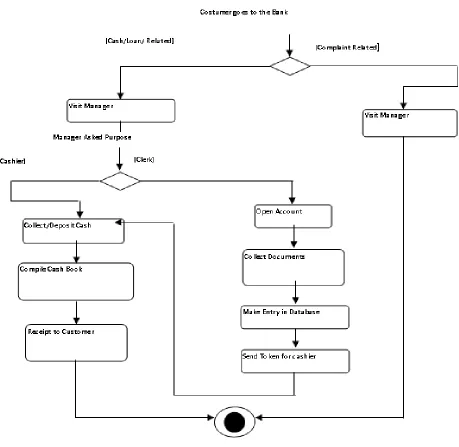
Fig 2. Shows the For Activity Diagram
Manager ask the customer for the purpose of visit, Then he direct him for further process, If customer is having complaint, Manager will look farward in to the matter If new account is to be opened clerk will take the documents and open account.
Clerk will issue the token for the cashier
Cahier will collect or give the case as per the token given by the clerk
[image:6.612.68.539.193.711.2]Customer will collect the compiled pass book.
Table 1 - Feature comparison of popular OO languages
Inheritance Polymorphism Typing Genericity
ANSI C++ Multiple Single Strong Yes
Java 1.3 Single Implementation
Multiple Interface
Single Strong No
CLOS Multiple Multiple Optional No
Ada 95 Single Single Strong Yes
Eiffel Multiple Single Strong Yes
Smalltalk-80 Single Single Untyped No
Table 2: Programming object oriented concepts
OOAD C C(files) C++ Java
Class Struct Separate file Class Class
Object Variable None Variable variable
Inheritance None None Derived class Subclass
Aggregation Nested struct None Nested class Reference
Association Pointer None Pointer Reference
Aggregation Data member Static data Data member Data member
Service External function External function Member function Member function
Message Function call Function call Function call Function call
Figure 2. Activity Diagram of BAS
IX. CONCLUSION
In this paper Object Oriented Analysis Benefits like maintainability, reusability, productivity and OOA Methods like Finding class and object, Identifying structures, Defined subject, Defining attributes, Defining services are explained. Also Object Oriented Design Benefits like Reusability, Extensibility, Robustness and OOD process like oriented analysis, oriented design, Object-oriented programming are explained. Object Oriented concept as class, object, Polymorphism, inheritance, abstraction, encapsulation, aggregation, association are summered up. Traditional software-engineering techniques were based upon the top-down structured design method, which focuses on algorithmic decomposition, i.e. the process of decomposing a
the experimental approach, data collection and encoding scheme, and subsequent interpretation of data. This paper is concerned primarily with Object-Oriented Analysis and Design (OOAD) as opposed to other parts of the software development lifecycle. This is because if the initial process of analysis and abstraction is flawed, the subsequent OOD produced will not sufficiently resemble the original problem at either a semantic or structural level. This negatively influences all subsequent steps in the software-development lifecycle, rendering them tedious and error-prone. The importance of analysis and design in comparison to the later stages of the development lifecycle has been widely described in the literature.
X. REFERENCES
[1]. Empirical Studies of Object-Oriented Artifacts, Methods, and Processes: State of the Art and Future Directions L. BRIAND
Carleton University, Canada E. ARISHOLM University of Oslo, Norway S. COUNSELL Birbeck College, University of London, K F. HOUDEK Daimler-Chrysler AG, Germany P. TH´EVENOD–FOSSE LAAS–CNRS, France, WORKSHOP AND CONFERENCE REPORTS
[2]. Srivastava, N.P.S. and S. Sabharwal, 2006. The classification framework for model transformation. J. Comput. Sci., 2: 166-170. DOI:10.3844/jcssp.2006.166.170
[3]. Applying Object-Oriented analysis and design : Article: Jean-Marc Nerson
[4]. de Champeaux, D., D. Lea, and P. Faure. The Process of Object-Oriented Design. In Proc. of OOPSLA'92. 1992. [5]. Jacobson, I., G. Booch, and J. Rumbaugh, The Unified
Software Development Process. 1999, Reading,
Massachusetts: Addison-Wesley.
[6]. Gerhard Fischer. Cognitive view of reuse and redesign. IEEE Software, 4(4):60-72, 1987.
[7]. L. Peter Deutsch. Design reuse and frameworks in the smalltalk-80 system. In Software Reusability - Volume II: Applications and Experience, pages 57-72, 1989.
[8]. Ralph E. Johnson and Brian Foote. Designing reusable classes. Journal of Object-Oriented Programming, 1(2):22-35, 1988.
[9]. William F. Opdyke and Ralph E. Johnson. Refactoring: An aid in designing application frameworks and evolving object-oriented systems. In Proceedings of Symposium on Object- Oriented Programming Emphasizing Practical Applications (SOOPPA), September 1990.
[10]. Arthur J. Riel:Object-Oriented Design Heuristics.Addison-Wesley May 1996.
[11]. Booch, G.: Object-Oriented Analysis And Design With Applications, 1991.
[12]. Jacobson, I., Christerson, M., Jonsson, P., and Overgaard G.: Object-Oriented Software Engineering: A Use-Case Driven Approach, Addison-Wesley, 1992
[13]. Rumbaugh, J., Blaha, M., Premerlani, W., Eddy F. and Lorensen, W: Object- Oriented Modeling and Design, Prentice-Hall, 1991.
[14]. Booch, G.: Object-Oriented Analysis And Design With Applications, 1991.
[15]. Jacobson, I., Christerson, M., Jonsson, P., and Overgaard G.: Object-Oriented Software Engineering: A Use-Case Driven Approach, Addison-Wesley, 1992
[16]. Rumbaugh, J., Blaha, M., Premerlani, W., Eddy F. and Lorensen, W: Object- Oriented Modeling and Design, Prentice-Hall, 1991.
[17]. Coplien, J.O. Software Design Patterns: Common Questions & Answers. in Proc. Of Object Expo New York. 1994. NY: SIGS Publications.
[18]. Alexander, C., et al., A Pattern Language. 1977, NY: Oxford University Press.
[19]. Gamma, E., et al., Design Patterns: Elements of Reusable Object-Oriented Software. 1995, Reading, Massachusetts: Addison-Wesley.
[20]. The Unified Modeling Language Resource Center
[21]. Selic, B., G. Gullekson, and P. Ward, “Real-Time Object Oriented Modeling”, John Wiley & Sons, Inc. 1994
[22]. Coad, P. and Yourdon, E. 1991. Object-Oriented Analysis. Prentice Hall, Englewood Cliffs, N.J.
[23]. Towards an Object-Oriented Analysis and Design method for Hardware/Software Systems. A Case Study. Erik Hansen, 1995
[24]. Booch, G., Object-Oriented Design with Applications, The Benjamin/Cummings Publishing Company Inc., Redwood City, CA, 1991.
[25]. Coad, P., Yourdon, E., Object Oriented Analysis (2nd Edition), Yourdon Press, Englewood Cliffs, N.J., 1991. [26]. Coad, P., Yourdon, E., Object Oriented Design, Yourdon
Press, Englewood Cliffs, N.J., 1991.
[27]. Martin, J., Odell, J., Object Oriented Analysis and Design, Draft manuscript, 1992.
[28]. Rumbaugh, J., Blaha, M., Premerlani, W., Eddy, F., Lorensen, W., Object Oriented Modelling and Design, Prentice-Hall, Englewood Cliffs, N.J., 1991.
[29]. Shlaer, S., Mellor, S.J., Object-Oriented Systems Analysis: Modeling the World in Data, Yourdon Press, Englewood Cliffs, N.J., 1988.
[30]. Wirfs-Brock, R., Wilkerson, B., Wiener, L., Designing Object Oriented Software, Prentice-Hall, Englewood Cliffs, N.J., 1990.