334
Performance Evaluation of Decode-and-Forward
Relaying for Cellular Communication Network
Nikhila G. Thomas
1, Niyas K. Haneefa
2Department of Electronics & Communication Engineering1, Telecommunication Engineering2 PG scholar1,Assistant Professor2, Mar Baselious College of Engineering & Technology, Nalanchira,
Trivandrum,Kerala1,2
Email: [email protected]1 ,[email protected]2
Abstract-In this paper, the performance of decode –and-forward relaying over multiple fading channels is been analyzed. Here at first overviewed traditional relaying techniques and compared it with coded cooperative relaying. BER performance the different schemes are analyzed and the results shows that coded cooperative relaying give better performance in terms of BER analysis. A new technique called network Coded cooperative relaying is introduced, analyzed the new scheme in terms of blocking probability and spectral efficiency. Diversity technique enhances link quality and increasing network capacity. Network coding achieves higher diversity order than other conventional relaying schemes. And the result shows that network coded cooperative relaying outperforms conventional relaying and non-relaying scheme. For improved performance for cell edge users also, location of relay based on distance measurement is also performed. Due to this cell center users also give better performance similar to cell edge users.
Index Terms-Cooperative relaying; coded cooperation; Network coding, relay selection..
1. INTRODUCTION
Cooperative relaying is considered as a most promising and efficient technique for improving spectral efficiency for wireless network. The goal of cooperative communication is improve the overall network performance. In communication, cooperation is of two types, implicit cooperation and explicit cooperation. Our area of interest is the cooperative relaying, which is an explicit cooperation. Explicit cooperation means there a particular frame work is being developed for supporting the cooperation by design. The main idea behind cooperative relaying is that a device is transmitting a signal to the receiver device, Another device which overhear this signal will send this overheard signal to the final destination and the destination device will combine these two received signal and will do perfect decoding. Today wireless communication has become an essential part in everyone’s day to day life. Most of the users are using smartphones. This powerful mobile terminals demanding for high end services such as huge data transfer, multimedia services etc. The main challenge faced by todays cellular communication network is that the transmitting the signals from source to destination without degrading the signal. Due to fading, path loss, noises and spectrum inefficiency the current cellular system is incapable of providing higher throughput and sufficient coverage to the users.Cooperative relaying offers considerable improvement. Cooperative relaying mainly consists of two types amplify-and-forward (A&F), decode and forward(D&F). A&F relaying forwards just the amplified version of the received signal. D$F relaying decodes the received signal, re-encode it and forward
to the final destination. So here coding can also be achieved.
In terms of network capacity for the channels and thereby providing a better way to meet the increasing demand for high data transfer for downlink system. It makes use of cooperative diversity principle for enhancing reliability efficiency and reliability of transmission [4]. This cooperative diversity scheme will mitigate the fading and interference effect. In relay aided cellular network Relay station are usually helps in forwarding the received signal to the respective destination i.e., from the Base Station(BS) to the Relay station (RS) for getting much higher Signal-to-interference ratio mainly for cell edge user, for increasing the overall network throughput[2].
335 coding which send a linear combination of the
[image:2.595.76.278.162.297.2]received packets of data. Physical layer network coding which implies the network coding occurs naturally by the super imposition of electromagnetic waves on one another [4].
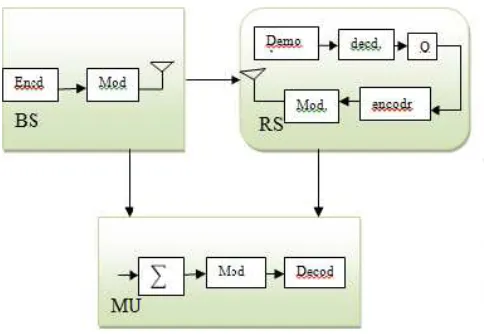
Fig.1: Conventional non relaying and relaying schemes a)traditional non-relaying scheme b) relaying scheme (diversity=1) c) cooperative
relaying(diversity=2) [1]
The paper is organized as follows, first section includes the system model then follows the analysis of existing relaying techniques modeled a network coding in cooperative relaying. Finally done the simulation for the proposed scheme and the results are being analyzed and summarized.
2. SYSTEM MODEL
Our model consists of a multi node cooperative relay, in which the Source node /Base Station (BS) want to communicate with the destination/Mobile Users (MU) over a Rayleigh faded channel. Here for transmission, system under consideration consists of Relay Stations (RS) for forwarding the signal which is coming from BS to MU. Decode-and-Forward relaying having constant power is considered. The general equation for received signal over a channel H with energy Eb can be given as,
=
| |
+ ( )
(1)
Where N(t) represents the additive Gaussian noise at time t.
2.1. Decode-and-Forward(D&F) Cooperative Relaying
In (D&F) strategy, the relay first decodes the received signal. If decodes successfully re-encode it and forward to the destination. So along with diversity gain, coding gain is achieved here.
The received signal during the first hop
from
source directly to destination can be
represented in the form
,=
|
1|
+
(2)
=
|
2|
+
(3)
where , are the received signal at the destinations and relay respectively. H1€C Nd*NS and
H2€C NR*NS denote the spatially correlated Rayleigh
distributed channel from the source to the destination and source to the relay respectively with AWG noise with zero mean and variance N0/2.
At the second hope, the relay transmits the encoded signal to the destination and finally receiver decoupled the signal and it is denoted as,
=
‖
3‖
2+
(4) is the transmitted energy at the relay, H3 channel matrix between relay and destination and is the filtered Gaussian noise.Fig 2: Block diagram representing D&F strategy .
3. PROPOSE NETWORK CODING
METHOD
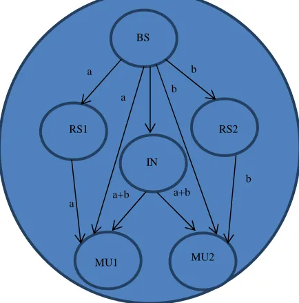
From the cell model of Figure 2 (a), considering hexagonal cell model and it is divided into six equidistant sub regions. If a sub region consist of two mobile users who need to communicate with a common base station and that type of mobile units (MUs) are called cooperation candidate MUs. If this condition occurs the proposed NC2R will start working. Here they can take advantage of their common Relay station which are in cooperation mode.
[image:2.595.314.556.298.465.2]336 Step 1: BS send the signal ‘a’ to RS1 and MS1, Also
the signal ‘b’ to RS2 and MS2.
Step 2: RS1 and RS2 decodes the signal ‘a’ and ‘b’. Also an intermediate node will combine the two received signals and forward the combination ‘a+b’ to both MS1 and MS2. And the decoded signals a and b were re-encoded and forward to MS1 and MS2 respectively.
Step 3: MS1 and MS2 extract a andb from
the three signal samples (i.e., a (or b) through direct path, a(or b) from relay a+b) received from BS, RS1 and RS2 respectively and then both of them do Maximal Ratio Combining (MRC) [8] to obtain the expected signals, i.e., a and b, respectively.
When there is a special situation occurs, if MS1 cannot find another CMS who wants to download data from the local BS within a certain waiting period. In this case NC2R methods will allow the Mobile User to select its local Base Relay station to download its signal of demand. And remaining steps are similar to the conventional cooperative relaying case,
Step 1: BS transmit signal to the corresponding destination and MS and its local RS.
[image:3.595.71.288.430.650.2]Step 1: RS station decodes the received signal and if successfully decoded, it is being re encoded and forwards the signal to corresponding Mobile User. Step 3: MU will do maximal Ratio combining to extract the original signal from the two copies of the signal.
Fig. 3: Network Coding in Cooperative Relaying From fig.3 NC2R it is clear that the end user receives 3 copies of the transmitted message thereby achieving a siversity order of 3 and from the figure 1a) and 1b) shows that occures only one copy of the message and the diversity order will be 1 and the in figure 1c) the diversity order will be two. Diversity, is a main part of broadcasting of wirelesss channels, is
used to combat fading effects by increasing the signal-to-noise ratio (SNR) of the received signals. SO NC2R have high SNR due its higher diversity order than other 3 scenerios.Consequently the diversity oreder can be calculated using the general form, lim →∝"()*#$%&' "= -d
Where +, is the probability of error.
4. SINR ANALYSIS
As interference limited network, CDMA network is been preferred for transmission, CDMA network is interference limited multiple access system, where each channel is disguised by using unique spreading codes. Each user has its own unique spreading codes. CDMA transmits signals in the same frequency band. Due to channel fading and noise MAI cannot be removed completely. And the system is got interfered by the transmitted power of the neighbouring RSs and BSs. denoted as inter channel interference. For convenience here are considering only 6 local BSs and 42 RSs, which includes 6 local RSs and 36 neighbouring RSs in the same cell.
In order for clarity for characterising interference effects, assumed the below given notation for received and transmitted power,
P
B: BSs transmitted powerPR: Transmitted power of relay station
dBM: distance between target local BS and MS
dMBi: distance between target MU and i/0 BS
PM :received power of the target MU
PlBN1: Received power of the total signal transmitted
from BS to all the users in N1 of current cell at the target MU.
PlBN2: Received power of the total signal transmitted
from BS to all the users in N2 of current cell at the target MU.
PnBN : Received power transmitted by the six
neighbouring BSs to all their users at the target MU. PRN : Received power transmitted by the local RSs
and neighbouring RSs located in the six nearest neighbouring cells to their users at the target MU
Therefore the total interference at the target MU can be given as,
1
2= 3
45 1+ 3
45 2+ 3
5+ 3 − 3
78--- (5)
The above equation indicates that all received power induces interference to the desired signal except the part of the desired signal.
Once the total interference is determined it is easy to calculate Signal-to-Interference ration (SINR) for the proposed NC2R by using the general formula[1],
91
=
:;<=>?@A@B C (6)
Where,
D = E/
, W bandwidth of the CDMA network and R is the transmission rate. ForBS
RS1
IN
RS2
MU1 MU2
a
a b
b
a
b
337 convenience set
G
=0, so the codes are perfectlyorthogonal if
G
=1, the codes are totally non-orthogonal. If it is non-orthogonal interferences will get maximized.5. SIMULATION RESULTS
Simulations are performed to evaluate the performance of the proposed algorithm and it is based on spectrum efficiency and blocking probability. Still it is difficult to identify the best relay out of the many.
A) Simulation Parameters
Here considering a hexagonal model with 7 cell reuse and number active users assumed to 101.This active users are uniformly distributed in cell. Location of the relay station is characterised on the basis of the distance between RS and BS and it is within the range[0,1].
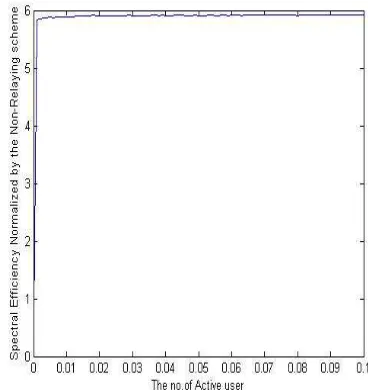
From first result it is shown that proposed method will give better performance to cell edge user. bUt cell- centre users suffer from interference, because base station transmits the edge signal twice and this will increase the amount of interference in the cell centre user. To improve the performance here also considering distance measurement it is an important factor which determines the performance. And it is observed that relatively law blocking probability can be achieved for cell-centre users when distance<0.6 and also high spectral efficiency can be achieved in the range 0.4<d<0.6. From the plot it is clear that NC2R achieves lower blocking probability and higher spectral efficiency for both cell-centre and cell-edge user if the distance come under the range 0.4<d<0.6.
Figure 4 represents the case in which there is no distance consideration made. So from the graph it is clear that the cell-edge users shows lower spectral efficiency and higher blocking probability blocking probability. But the sacrifice of performace for cell-centre users are considerably very small when comparing with the performance improvement achieved by cell-edge users Parameter considered here are α=4,ŋ=0.5,R=1000.
If the distance from Base Station to Relay Station in between 0.4 to o.6 it is possible to improve the spectral efficiency and reduce the blocking probability of cell-center users.
Fig 4. (a) Spectral efficiency of cell-centre users
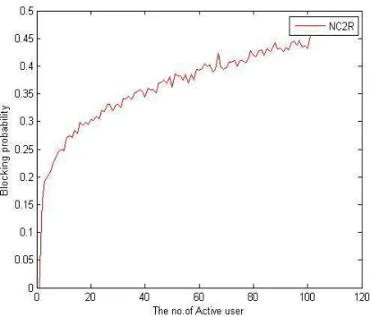
Fig 4 (b) Blocking probability of cell-centre users
[image:4.595.314.505.98.276.2] [image:4.595.311.504.304.476.2] [image:4.595.316.500.504.699.2]338 Fig 4 (d) Blocking probability of cell-edge users
CONCLUSION & FUTURE WORK This study analysed different types of decode-and-forward relaying schemes. Proposed a new technique called network coding in cooperative relaying. This technique achieves a diversity order of 3 for downlink cell-edge users. However here also analysed the SINR for Network Coding scheme with consideration of channel fading, ICI and MAI. Simulation result shows that network coding when combined with cooperative relaying will achieve low blocking probability and higher spectral efficiency for total cell users and especially cell-edge users. This highly improves the network performance.
There are some issues which still kept unsolved. One among that is no error correction codes are specified here this lead to error propagation in the system. Channel coding when implemented into the current network coded system will result in more error free transmission.
Acknowledgments
I thank the almighty God for helping me for successfully completing a part of my thesis work. I thank my parents for all those support and encouragement. The most importantly I thank my guide Mr.Niyas K. Haneefa, without him my project will not be completed. Last but not the least I thank all professors and lab assistants, of Mar Baselious College of Engineering and technology for their continuing support. I thank all my dear friends. REFERENCES
[1]XIONG Ke1, FAN Pingyi, YI Su, LEI Ming, ‘Network Coding- Aware Cooperative Relaying for Downlink Cellular Relay Networks’, IEEE Vehicular Technology Magazine, 2013.
[2]Gerhard Kramer, Member, IEEE, Michael GastpaMember, IEEE, and Piyush Gupta, Member, IEEE,"Cooperative Strategies and Capacity Theorems for Relay Networks", IEEE Transactions On Information Theory, Vol. 51, NO. 9, september 2005.
[3]Mohammed W. Baidas, Allen B. MacKenzie and R. Michael Buehrer,“Network-Coded Bi- Directional Relaying for Amplify-and- Forward Cooperative Networks:A Comparative study”,IEEETransactions on wireless communications, Vol. 12, NO. 7, July 2013. [4]Yixin Li, Fu-Chun Zheng, Michael Fitch,
“Physical layer network coding with channel and delay estimation”,IET Communications Vol. 7, Iss. 11, pp. 1109–1116, April 2013.
[5]Yinbin Liang and Venugopal V. Veeravalli, "Cooperative Relay Broadcast Channels", International Conference on Wireless Networks, Communications and Mobile Computing,2005. [6]Yue Ma, Lihua Li, Jin Jin and YijingLiu,"A Novel
Network Coded Relay-AssistedHybrid-ARQScheme",The 10th Annual IEEE CCNC- Wireless Communications Track, 2013.
[7]Vijayvaradharaj T. Muralidharan and B. SundarRajan, “Wireless Network Coding forMIMO Two-Way Relaying”, IEEE Transactions on Wireless Communications, vol. 12, NO. 7, July 2013.
[image:5.595.82.289.99.276.2]