IJEDR1402179
International Journal of Engineering Development and Research (www.ijedr.org)2409
Design and Analysis of Six Stroke Internal
Combustion Engine
1
Tejaskumar U Kothari,
2Mr.Devranjan Kumar,
3Mr.K.D.Tandel
1M.E. Student, 2,3Asst.Professor
1,2Thermal Engineering, SVMIT, Bharuch-392001, Gujarat, INDIA 3
GEC, Valsad- Gujarat, INDIA
1[email protected], 2[email protected], 3[email protected]
________________________________________________________________________________________________________
Abstract— The modern four stroke internal combustion engine has been widely applied due to excellent power to weight ratio and reliability. However, the major downside of the even most efficient modern 4 stroke engine is the production of significant amounts of excess heat energy, dissipated though the cylinder walls of the engine and expelled as waste energy during the exhaust stroke of the cycle. The development of a more efficient six stroke internal combustion engine for increasing the efficiency of four stroke engine for that the final two strokes designed to used of exhaust and convert it into power stroke and finally six stroke working as exhaust stroke and also batter scavenging.Some of basic modifications are done in four stroke engine and made a six stroke engine we can increase the brake thermal efficiency of the engine. Also the dramatic reduction in pollution and batter scavenging is occurs.
Key Words— 2-Cylinder 4-Stroke Diesel Engine, Cam-Shaft Design, Flywheel,
1.INTRODUCTION
As the time passes, it is believed that the petroleum products and crude oil will be not enough and will be costly. Various researches are going on for the improvement of fuel economy of engines. However as the demand and availability for petrol and diesel is somewhat unbalanced and there is a need to balance since that is mainly happened due to enormous increase in number of vehicles. If the same situation continues then the scenario will be more disastrous and petrol and diesel will be more costly and limited. With increased use and the depletion of fossil fuels, today more emphasis is given on the alternate fuels.
1.1.1 OBJECTIVE
Reduction in fuel consumption Dramatic reduction in pollution
Better scavenging and more extraction of work per cycle
The term six stroke enginedescribes two different approaches in the internal combustion engine, developed since the 1990s, to improve its efficiency and reduce emissions.
In the first approach, the engine captures the waste heat from the four stroke Otto cycle or Diesel cycle and uses it to get an additional power and exhaust stroke of the piston in the same cylinder. Designs either use steam or air as the working fluid for the additional power stroke. As well as extracting power, the additional stroke cools the engine and removes the need for a cooling system making the engine lighter and giving 40% increased efficiency over the normal Otto or Diesel Cycle. The pistons in this six stroke engine go up and down six times for each injection of fuel. These six stroke engines have 2 power strokes: one by fuel, one by steam or air. The currently notable six stroke engine designs in this class are the Crower's six stroke engine, invented by Bruce Crower of the U.S.A; the Bajulaz engine by the Bajulaz S A Company, of Switzerland; and the Velozeta‟s Six-stroke engine built by the College of Engineering, at Trivandrum in India.
The second approach to the six stroke engine uses a second opposed piston in each cylinder which moves at half the cyclical rate of the main piston, thus giving six piston movements per cycle. Functionally, the second piston replaces the valve mechanism of a conventional engine and also it increases the compression ratio. The currently notable six stroke engine designs in this class include two designs developed independently: the Beare Head engine, invented by Australian farmer Malcolm Beare, and the German Charge pump, invented by Helmut Kottmann.
Engineer Samuel Griffin was the first six stroke engine developer in the world. Griffin had found this engine in 1883 and this engine mainly used for electric power generation. Only two known example of a Griffin six stroke engine today. One is in the Anson engine museum. The other was built in 1885 and for some years was in the Birmingham Museum of Science and technology.
IJEDR1402179
International Journal of Engineering Development and Research (www.ijedr.org)2410
system radiator is required. Energy that is dissipated in conventional arrangements by the radiation cooling system has been converted into additional power strokes. In Crower's prototype, the water for the steam cycle is consumed at a rate approximately equal to that of the fuel, but in production models, the steam will be recaptured in a condenser for re-use.Malcolm Beare 47 year old Australian wheat farmer is the inventor of this six stroke engine. Actually the name six stroke engines was introduced by Malcolm Beare. Beare created an innovative hybrid engine, combining two-strokes in the top end with a four-stroke above the middle portion. So by adding this four plus two equals six, he derived the name six stroke engines. Below the cylinder head gasket, everything is conventional, in his design. So one main advantage is that the Beare concept can be transplanted to existing engines without any redesigning or retooling the bottom end and cylinder. But the cylinder head and its poppet valves get thrown away in this design. To replace the camshaft and valves, Beare used a short-stroke upper crankshaft complete with piston, which is driven at half engine speed through the chain drive from the engine. This piston moves against the main piston in the cylinder and if the bottom piston comes four times upwards, upper piston will come downwards twice. The compression of charge takes place in between these two pistons. Much higher compression ratios can be obtained in this engine. Malcolm used on his first six-stroke, based on a Honda XL125 farm bike. Malcolm Beare claims his engine is 35% more economical at low revs/throttle openings than an equivalent conventional engine and 13% less thirsty at high rpm/full throttle.
In Charge pump engine, similar in design to the Beare head, a „piston charger‟ replaces the valve system. The piston charger charges the main cylinder and simultaneously regulates the inlet and the outlet aperture leading to no loss of air and fuel in the exhaust. In the main cylinder, combustion takes place every turn as in a two-stroke engine and lubrication as in a four-stroke engine. Fuel injection can take place in the piston charger, in the gas transfer channel or in the combustion chamber. It is also possible to charge two working cylinders with one piston charger. The combination of compact design for the combustion chamber together with no loss of air and fuel is claimed to give the engine more torque, more power and better fuel consumption. The benefit of less moving parts and design is claimed to lead to lower manufacturing costs. Good for hybrid technology and stationary engines. The engine is claimed to be suited to alternative fuels since there is no corrosion or deposits left on valves. The six strokes are: aspiration, pre-compression, gas transfer, compression, ignition and ejection.
Mechanical Engineering students of the college of Engineering in Trivandrum, in the year 2006 made this six stroke engine as a part of their B.Tech project. After the completion of the course they formed the company Velozeta with the help of state and central government. They have got the patent of this engine also. In Velozeta‟s six stroke engine, a four-stroke Honda engine was experimentally altered to build the six stroke engine. The first four strokes of this engine are just like a conventional four stroke engine. The additional two strokes are for better scavenging and cooling of the engine which is provided by a secondary air induction system.
1.1.2 PREVIOUS WORK
In six stroke engine, there are additional two strokes, namely another power and exhaust strokes. The engine works through harnessing wasted heat energy created by the fuel combustion. After the combustion stage water is injected into the superheated cylinder. The water explodes into steam and force the piston down. It in turn helps to cool the engine. That resulted in normal levels of power but using much less fuel. It also has the advantage of not requiring an external cooling system. In order to achieve these benefits, major modifications of conventional internal combustion engine must be done.
1.1.3 LIMITATION OF SIXSTROKE INTERNAK COMBUSTION ENGINE
Engine size increases due to number of cylinder and additional components. Higher manufacturing cost of six stroke engine.
1.1.4 CONCEPT OF SIX STROKE INTERNAL COMBUSTION ENGINE
IJEDR1402179
International Journal of Engineering Development and Research (www.ijedr.org)2411
Figure 1 Concept of Six Stroke EngineHere fuel is injected once in every 3 complete cycles of the crankshaft which is any time better than a 4 stroke ICE where fuel is injected once in 2 complete cycles of the crankshaft. It should be noted that efficiency of the 6 stroke ICE is more than the existing 4 stroke ICE. Major type of secondary fuels used in the 5th stroke is air and water. Many types of 6-ICE have now been designed on these 2 fuels of which few important types will be discussed.
2. ENGINE PARTS MODIFICATION
2.1 Crankshaft To Camshaft Speed Ratio
The original angular speed of the camshaft is one-half that of the crankshaft, such that the camshaft rotates once for every two revolutions (or four strokes) of the crankshaft. The crankshaft pulley of the unmodified (4-stroke engine) engine has a 21 tooth and camshaft pulley of the engine has a 42 tooth. In conventional four stroke engine ,the crankshaft must rotate720° while the camshaft rotates 360° to complete one cycle. For six-stroke engine, the crank shaft must rotate 1080°to rotate the cam shaft 360° and to complete one cycle. Hence their corresponding speed ratio is 3:1. In modified engine a camshaft pulley has a 42 tooth which is same as that was in unmodified (4-stroke engine) engine and crankshaft pulley has a 14 tooth which is 1/3 of the camshaft pulley because the rotation ratio of crankshaft to camshaft is 3:1 in six stroke engine. So it is necessary to keep camshaft pulley three time bigger than crank shaft pulley.
IJEDR1402179
International Journal of Engineering Development and Research (www.ijedr.org)2412
Figure 3 Inlet and Exhaust Manifold of Four Stroke Engine
As shown in figure 4 the common inlet manifold of four-stroke engine parted by welding a plate between the common inlet manifold. In six-stroke engine fuel is supplied in only 1st cylinder and not in second cylinder but exhaust of first cylinder is transferred to second cylinder. For carrying out the exhaust gases of second cylinder, inlet manifold of second cylinder is used for this purpose.
The plate welded between the inlet manifold is of aluminum. Because manifold is made of aluminum. The main benefit of this manifold is exhaust gases come out at high temperature so it will preheat the inlet air so increase the combustion rate.
Figure 4 Modified Inlet and Exhaust Manifold of Six Stroke Engine
IJEDR1402179
International Journal of Engineering Development and Research (www.ijedr.org)2413
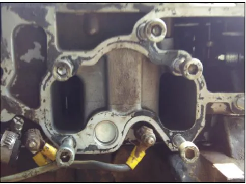
Figure 5 Common Exhaust Manifold of Six Stroke Engine
In six stroke engine exhaust of first cylinder is get used to run the second cylinder, therefore to transfer exhaust of first cylinder to second cylinder exhaust manifold is sealed using packing at the connection where two exhaust manifold are meet so that exhaust gas is transferred to the second cylinder instead of exhauster.
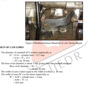
Figure 6 Modified Exhaust Manifold of a Six Stroke Engine
2.3 DESIGN OF CAM LOBES
The diameter of camshaft (D‟) is taken empirically as D‟ = 0.16 × cylinder bore + 12.7 mm = 0.16 × 75 + 12.7
= 35.1 say 36 mm
The base circle diameter is about 3 mm greater than the camshaft diameter. Base circle diameter = 36 + 3
= 36 say 40 mm
The width of cam is taken equal to the width of roller, i.e. 14 mm The width of cam (W‟) is also taken empirically as
W‟ = 0.09 × cylinder bore + 6 mm = 0.09 × 75 + 6
= 18.6 mm
IJEDR1402179
International Journal of Engineering Development and Research (www.ijedr.org)2414
Figure 7 Cam Profile for First Cylinder Inlet Valve Figure 8 Cam Profile for First Cylinder Exhaust Valve
2.3.2 CAM PROFILE FOR SECOND CYLINER INLET AND EXHAUST VALVE
Figure 9 Cam Profile for Second Cylinder Inlet Valve Figure 10 Cam Profile for Second Cylinder Exhaust Valve
IJEDR1402179
International Journal of Engineering Development and Research (www.ijedr.org)2415
Figure 11 Cam Profile for Fuel Injector2.3.4 MODIFIED SIX STROKE ENGINE CAMSHAFT
Figure 12 Modified Six Stroke Engine Camshaft
2.4 ENGINE PERFORMANCE TEST
Sr.no Observation 1 2 3 4 5
1. Load , W in kg 0 0 0 0 0
2. Speed , N in rpm 900 1200 1500 1800 2000
3. Volume of fuel , Vf in m3 10 × 10-6 10 × 10-6 10 × 10-6 10 × 10-6 10 × 10-6
4. Fuel consumption time, tf in sec 42 34 30 26 24
Table 1 Six Stroke Engine Test Observation Table
Density of fuel , ρf = 804 kg/m3
Calorific value of fuel =43500 kJ/kg
Table 2 Properties of Material B.P. =
=
= 2.73 kW
Fuel consumption mf = (Vf / tf) × ρf = (10×10-6 / 42) × 804
= 1.91 × 10⁻⁴ kg/sec Break thermal efficiency,
ηbth =
= = 0.3285
ηbth = 32.85 %
IJEDR1402179
International Journal of Engineering Development and Research (www.ijedr.org)2416
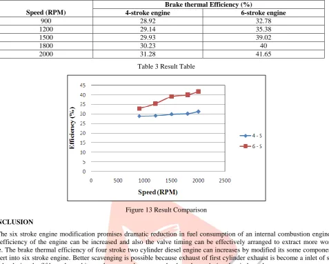
Figure 13 Result ComparisonCONCLUSION
The six stroke engine modification promises dramatic reduction in fuel consumption of an internal combustion engine. The fuel efficiency of the engine can be increased and also the valve timing can be effectively arranged to extract more work per cycle. The brake thermal efficiency of four stroke two cylinder diesel engine can increases by modified its some component and convert into six stroke engine. Better scavenging is possible because exhaust of first cylinder exhaust is become a inlet of second cylinder during the fifth stroke and its work as second power stroke the exhaust during the sixth stroke.
REFERENCES
[1] George Marchetti and Gilles Saint-Hilaire “A Six-Stroke, High- Efficiency Quasiturbine Concept Engine with Distinct, Thermally-Insulated Compression and Expansion Componets.” (September-2005)
[2] Mr.Krishna Kanth, Mr.Shinivas. D. “Six Stroke Engine” (0109), www.Jntuworld.com
[3] James C. Conklin, James P. Szybist “ A highly efficient six stroke internal combustion engine cycle with water injection for in-cylinder exhaust heat recovry” Energy 35 (2010) 1658-1664
[4] M.M.Gasim, L.G.Chui, K.A.Bin Anwar “ Six Stroke Engine Arrangement” Proceedings of the 15th Int. AMME Conference, 29-31 May, 2012
[5] Amit Bhatia, Ashish Mendiratta, Mayank Vaish “six stroke engine” (0109) www. Jntuworld.com
[6] Chinmayee Karmalkar, Vivek Raut “Analysing the implementation of six stroke engine in a hybridcar”. (January 10,2014)
[7] Kiran P “ A feasibility study on waste heat recovery in six stroke engine” (2013)
[8] Mojtaba TAHAN, Saeed JAVAN, Mojtaba BIGLARI, “ A comprehensive study on waste heat recovery from internal combustion engine using organic Rankine cycle ”.
WEBSITES
[9] http://www.mandieselturbo.com
[10] http://www.bajulazsa.com/site/sixstrokeexplanations.html [11] http://www.velozetas.com/site/sixstrokeexplanations;html