517
Radio Frequency Sensor-Based Traffic Light Control for Emergency Vehicles
Goshwe, Y. Nentawe, Okewu A. Victor and Kureve D. Teryima
ABSTRACT:
Most cities in Nigeria experience traffic congestions during peak periods because road transport remains the dominant mode of transportation in Nigeria. These congestions have the consequence of affecting the efficiency, reliability and safety of emergency vehicles in performing their duties which are vital for saving lives and reducing property losses. This paper presents a prototype of an intelligent RF based traffic control system for emergency vehicles that transmits using amplitude shift key modulation technique at a frequency of 433 MHz and maximum sensing distance of 65 meters. The system operates in two modes: normal and emergency sequences. Under normal sequence, the designed pass period per lane was 15 seconds and complete cycle is 45 seconds. Under an emergency sequence, the transmitted signal overrides the normal sequence of traffic because the microcontroller will run the interrupt service routine (ISR) or interrupt handler which will trigger the red light on all the lanes. The prototype constructed gave a sensing distance of 42.2 meters, pass period per lane of 12 seconds and a complete cycle period of 36 seconds.Keywords
-
Amplitude shift key modulation, Emergence vehicle, Microcontroller, Radio Frequency and Sensing distance.1
Introduction
Road transport remains the dominant mode of transportation and it contributes the most in fatalities, injuries and crashes in Nigeria [1]. Most emergency vehicles use this means of transportation, therefore the form critical part of modern human life because their efficiency, reliability and safety are vital for saving lives and reducing property losses [2]. Therefore, it is necessary to ensure that emergency vehicles can respond to emergency calls for an incident with minimum delay when the traffic is congested.
Often, emergency vehicles are permitted by law to break conventional rules in order to reach their destination at the fastest possible time, such as driving through an intersection when the traffic light is red or exceeding speed limit. Breaking of conventional traffics rules by emergency vehicles at junctions sometimes create conflicts that can cause emergency vehicle crashes or block lanes thereby increasing traffic response time.
Literatures have shown that the involvement of an emergency vehicle in a crash at road intersections has led to loss of lives and reduced overall efficiency of emergency response services [3,4,5,6]. This informed the need to facilitate the implementation of a higher payoff strategies to improve the safety of emergency vehicle passing through
signalized intersections. This paper presents an
implementation of an RF-based intelligent vehicle traffic control system using radio frequency for a cross-junction.
2
Methodology
The RF based intelligent traffic control system for emergency vehicles implemented has a transmitter and control units. The transmitting unit is planted in the emergency vehicle while the control unit is installed at a road junction. The transmitting unit uses amplitude shift key modulation technique and transmit the signal at 433 MHz.
The received signal is then decoded and sent as a digital signal to the external interrupt pin of the microcontroller. This then interrupts the normal sequence of traffic at the junction to make way for the emergency vehicle. When an emergency vehicle approaches 75 meters away from the junction, the transmission from the emergency vehicle is sensed by the control unit which then interrupts the normal
sequence of traffic at the junction by stopping all other vehicles at the junction to make way for the emergency vehicle. The microcontroller also responds to impulse from the radio frequency receiver to stop all traffic at the junction.
3
Hardware and Software Design
3.1 Selection of sensing distance
In Nigeria, emergency vehicles have speed limit of 80 km/hour within towns and cities they can negotiate junctions at speed limit of 30 km/hour [7]. Using a speed limit of 80 km/hr (22.3 m/s), for the emergency vehicles, a junction negotiating speed limit of 30 km/hr (8.33 m/s) and a five second’s time interval to get traffic halted at the junction, the distance of sensing of the emergency vehicles can be evaluated using the equation of motion given in equation (1.0
( )
1.0
Where s = distance (m), v = final velocity (m/s), u = initial velocity (m/s) and t = time (s), the sensing distance will be 65 meters.
3.2 Selection of transmission frequency
A wireless communication over 65 m range of distance would require the use of Radio Frequency which has
a speed of approximately m/s. The frequency of the
radio wave required can be calculated using equation (2.0)
2.0
Where c is the velocity of the wave and λ is the wavelength (the distance travelled in one cycle by the wave). Using the sensing distance of 65 m, the frequency of the wave will be 4 MHz but 315 MHz transmitter and 433 MHz receiver was used for the prototype and it is within the High frequency band.
3.3 Software Design RF-based Traffic Control System for Emergency Vehicles
the sequence. When an emergency vehicle is sensed, an external interrupt is generated through Pin 3 of Port 3 (P3.2). This triggers an emergency which overrides the normal sequence of traffic because the microcontroller will run the interrupt service routine (ISR) or interrupt handler. Upon receiving an interrupt, the microcontroller takes the display to state 9 where the red light on all the lanes comes ON and all other light goes OFF. The Truth Table for the eight states for normal traffic control is as shown on Table 1.0.
Table 1.0: Truth Table for the Eight States for Normal Traffic Control
Traffic Light
R A G GR Traffic
Light
R A G GR
Lane 1 0 0 1 0 Lane 1 0 1 1 0
Lane 2 1 0 0 0 Lane 2 1 1 0 0
Lane 3 1 0 0 0 Lane 3 1 0 0 0
Lane 4 1 0 0 1 Lane 4 1 0 0 1
STATE 1 STATE 2
Traffic Light
R A G GR Traffic
Light
R A G GR
Lane 1 1 0 0 1 Lane 1 0 0 1 1
Lane 2 0 0 1 0 Lane 2 0 1 1 0
Lane 3 1 0 0 0 Lane 3 1 1 0 0
Lane 4 1 0 0 0 Lane 4 1 0 0 0
STATE 3 STATE 4
Traffic Light
R A G GR Traffic
Light
R A G GR
Lane 1 1 0 0 0 Lane 1 1 0 0 0
Lane 2 1 0 0 1 Lane 2 1 0 0 1
Lane 3 0 0 1 0 Lane 3 0 1 1 0
Lane 4 1 0 0 0 Lane 4 1 1 0 0
STATE 5 STATE 6
Traffic Light
R A G GR Traffic
Light
R A G GR
Lane 1 1 0 0 0 Lane 1 1 1 0 0
Lane 2 1 0 0 0 Lane 2 1 0 0 0
Lane 3 1 0 0 1 Lane 3 1 0 0 1
Lane 4 0 0 1 0 Lane 4 0 1 1 0
STATE 7 STATE 8
When an emergency is approaching a junction, the transmitting unit is switched ON to enable the traffic control unit to interrupt all other vehicles and give priority to the emergency vehicle. The Truth Table of the emergency state is as shown on Table 2.0. The Truth Tables for the eight states during normal traffic control and the emergency states are used to develop the software. Each lane had a total pass duration of twelve (12) seconds and total stop duration of thirty six (36) seconds to make a complete cycle. Note that R = Red, A = Amber, G = Green and GR = Turn Right Green.
Table 2.0: Truth Table for Emergency State
Traffic Light R A G GR
Lane 1 1 0 0 0
Lane 2 1 0 0 0
Lane 3 1 0 0 0
Lane 4 1 0 0 0
EMERGENCY STATE
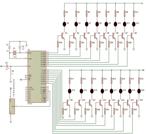
Figure 1.0 shows the circuit diagram of the control unit of an RF-based intelligent traffic system using the AT89S52 microcontroller with port 0 and port 2 used as the output port. These ports are used to bias the base of the transistors that are switching the light emitting diodes (LED) which are serving as the display. At any point in time, each of the outputs is either a high (5 V) or a low (0 V).
Figure 1.0: Circuit Diagram of the Control Unit of an
Four sets of LEDs were used in implementing the display with each set comprising of a Red, Amber, Green light and a right turn Green light indicators. Pin 3 of Port 3 is used as the R.F receiver input port and it is used to initiate an interrupt routine in an event of an approaching emergency vehicle. Since there are sixteen LEDs, and at each point in time they are either ON or OFF (1 or 0), sixteen bits will be required to represent or define a particular state.
4
Results
4.1 Traffic Light Control for Normal Sequence
The intelligent emergency vehicle traffic control system designed was tested and measurement taken to ascertain its performance. The device performs the dual functions of controlling normal traffic at the junction and also stopping all traffic at the junction if an emergency vehicle is approaching. Figure 2.0 shows snap shots of the LEDs for the eight states of the system during normal traffic control and they correspond to the truth table in Table 1.0.
519
State 1
State 2
State 3
state 4
State 5
State 7
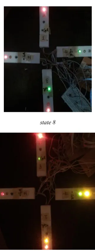
state 8
Figure 2.0: Snap Shot of the Eight States during normal
Traffic Control
Under normal traffic control, if the system is powered, the green LED on lane 1 turns ON simultaneously with the Red LED for all other lanes and the right turn green light for lane 4 as seen in Figure 2,0. This state lasted for seven seconds after which the Amber LED for lane 1 and 2 turns ON for another five seconds. At the expiration of five seconds, the green light on lane 2 turns ON with all other lanes showing Red with the exception of the right turn green light on lane 1.This cycle is repeated for all the eight states under normal traffic control.
4.2 Traffic Light Control for Emergency Mode Sequence
An emergency vehicle was simulated in the laboratory by turning on the transmitter and it override the sequence to turn ON all the Red LEDs for the four lanes as shown in Figure 3.0 to indicate an emergency vehicle is approaching. The transmitting unit was gradually moved away from the control unit until a green LED on one of the lanes
within the range of transmission. Measurements were taken for the four lanes under test and the average range obtained was 42.2 meters. It is worth noting that the results correspond to the truth table designed on Table 2.0 which means the system worked as designed.
Figure 3.0: Snap Shot of the Emergency State
5 Discussion
The code worked as expected both in simulation and the prototype constructed except that the pass duration realized in simulation and implementation were 14s and 12s respectively as against the designed value of 15 s and the stop duration for traffic in a lane in a complete cycle for simulation and implementation respectively were 42 s and 36s against the designed value of 45s. This difference may be due to the fact that in simulation, components values are ideal. Also the environment for simulation is assumed ideal as no environmental factor affects the simulation while in the implementation, component values have tolerances and environmental factor like temperature change can cause change in component values.
The sensing distance for emergency vehicles from the junction designed for was 65 m and was to be realized using a transmitter that could transmit signals at a frequency of 4 MHz. But for the unavailability of a 4 MHz transmitter, a 433 MHz transmitter was used in implementation and a sensing distance of 42.2 m was realized. One of the basic limitations to the realizable sensing distance is the power available to the transmitting section and the results agree with results obtained by [8].
6
Conclusion
521
sequence for both normal and emergency vehicles was achieved.
Reference
[1] Aworemi, J. R. Abdul-Azeez, I. A. Olabode, S. O. Analytical study of the casual factors of road traffic crashes in Southwestern Nigeria. Educational Research. 1(4), 2010, 118-124.
[2] A. Goel, S. Ray, N. Chandra. Intelligent Traffic Light System to Prioritized Emergency Purpose Vehicles based on Wireless Sensor Network. International Journal of Computer Applications 40(12), 2012, 36-39
[3] Xu Li, Wei Shu, Minglu Li, Hong-Yu Huang, Pei-En Luo, Min-You Wu. Performance Evaluation of Vehicle-Based Mobile Sensor Networks for Traffic Monitoring. IEEE transactions on vehicular technology, 58(4), 2009, 1647-1653.
[4] Albagul, A. Hrairi, M. Wahyudi, Hidayathullah, M.F. Design and Development of Sensor Based Traffic Light System. American Journal of Applied Sciences 3(3), 2006, 1745-1749.
[5] Sumaila, A. Road Traffic Trend and safety management in Nigeria. Journal of Geography and Regional Planning. 6(3), 2013, 53 – 62.
[6] YI-Shange, H. Design of Traffic Safety Control Systems for Emergency Vehicle Preemption Using Timed Petri Nets. Intelligent Transportation system. IEEE Transactions. 16(4), 2015, 2113-2120.
[7] Federal Road Safety Commission of Nigeria. The Nigeria Highway code. 2nd Edition. 2008, 67.