Cyclic Locking and Memristor-based Obfuscation Against
CycSAT and Inside Foundry Attacks
Amin Rezaei, Yuanqi Shen, Shuyu Kong, Jie Gu, and Hai Zhou
Northwestern University, Evanston, USA[email protected],{yuanqishen2020, shuyukong2020}@u.northwestern.edu, {jgu, haizhou}@northwestern.edu
Abstract—The high cost of IC design has made chip protection one of the first priorities of the semiconductor industry. Although there is a common impression that combinational circuits must be designed without any cycles, circuits with cycles can be combinational as well. Such cyclic circuits can be used to reliably lock ICs. Moreover, since memristor is compatible with CMOS structure, it is possible to efficiently obfuscate cyclic circuits using polymorphic memristor-CMOS gates. In this case, the layouts of the circuits with different functionalities look exactly identical, making it impossible even for an inside foundry attacker to distinguish the defined functionality of an IC by looking at its layout. In this paper, we propose a comprehensive chip protection method based on cyclic locking and polymorphic memristor-CMOS obfuscation. The robustness against state-of-the-art key-pruning attacks is demonstrated and the overhead of the polymorphic gates is investigated.
Keywords—Chip Protection; Cyclic Locking; Obfuscation; Memristor; CycSAT Attack; Inside Foundry Attack
I. INTRODUCTION
With increasing the design costs of Integrated Circuits (ICs), chip protection has become one of the main concerns for the semiconductor industry. By using Reverse Engineering (RE) techniques, gate-level netlist can be extracted and duplicated without the authorization of the chip holder [1]. Moreover, many semiconductor companies contract out manufacturing of their designs to third party foundries. With the growing number of untrusted foundries, the possibility of Inside Foundry Attack (IFA) is also escalating [5]. Locking is a logical request to make sure that the correct behavior only happens when a correct key is applied and the correct key cannot be easily figured out by studying the logic of the locked circuit. On the other hand, obfuscation is a structural request to make sure that the correct circuit cannot be revealed by any structural analysis of the obfuscated circuit. To protect IC design against RE and IFA, first the design should be locked and then obfuscated, while its functionality is preserved.
A. Challenges
A lot of research has been done in software protection. However, since the functionality of an IC may be completely or partially known by other parties, hardware protection is en-tirely different from software protection. Most of the previous works have focused on hardware protection for acyclic combi-national circuits. The main approach in acyclic combicombi-national protection is logic encryption in which the functionality of the circuit is locked by inserting key-controlled gates [6, 7] and
ŝƐĐŚĂƌŐŝŶŐ
ŚĂƌŐŝŶŐ
ZсZ
ŵĂdžZсZ
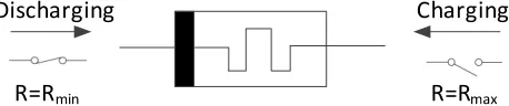
ŵŝŶFig. 1: Memristor (arrows show direction of the current)
then a logic resynthesis is done to obfuscate the whole circuit. A more advanced technique is called IC camouflaging, in which the cells are configured in a way that perform different functions, while maintain an identical look in RE-based attacks [8]. In this case the locking and the obfuscation are done concurrently.
However, the SAT-based attack [9] on acyclic combinational circuits allows the attacker to infer the correct values of the key inputs using only a small number of input-output observations taken from an activated IC. The proposed attack threatens almost all the previous efforts in acyclic locking. Even with applying incremental anti-SAT methods [10, 11], state-of-the art IC camouflaging techniques, that take advantage of dummy contact [12] and doping-based [13] obfuscations, are still vulnerable to IFA. Because in order to manufacture the chip, the third party foundry should have access to the connec-tivity information (i.e. dummy/true contacts and always-on/off CMOS transistors.) Thus, the main challenges in hardware protection are twofold:
• Proposing locking schemes to defeat key-pruning attacks; • Finding circuit obfuscation solutions to prevent IFA.
B. Contributions
the other hand, memristor [2, 3] -alongside resistor, capacitor, and inductor- is the forth basic nano-scale chip element where its resistance can be changed by the direction of electric current shown in Fig. 1. Memristor is known for its three main characteristics: 1) Non-volatility: Memristor is a non-volatile element that its resistance serves as a stored variable; 2) Compatibility: As memristor is compatible with CMOS structure, it is a supplementary element for integrated hybrid memristor-CMOS logic circuits; 3) Scalability: Memristor can be fabricated in high density at the intersection of nano-scale width metal lines located on top of the silicon layer.
One of the interesting usage of memristor is to build polymorphic memristor-CMOS gates [4]. Polymorphic gates are multi-functional gates, in which change of their behavior comes from modifications in the characteristics of their com-ponents (e.g. changing memristor’s resistance) after fabrication [14]. By taking advantage of polymorphic memristor-CMOS obfuscation, the layouts of the circuits with different func-tionalities may look exactly identical, making it impossible even for an inside foundry attacker to distinguish the defined functionality of an IC by looking at its layout. Thus, the contributions of this paper are twofold:
• Defeating the state-of-the-art key-pruning attacks by first converting the acyclic circuit to a cyclic one and then introducing hard cycles;
• Overcoming the problem of IFA by employing polymor-phic memristor-CMOS gates instead of using traditional dummy contact and doping-based solutions.
The rest of the paper is arranged as follows. Section II introduces a new CycSAT-proof logic locking scheme. Section III proposes two novel polymorphic memristor-CMOS gates to obfuscate cyclic circuits. The experimental results are shown in Section IV. Finally, Section V concludes the paper.
II. CYCSAT-PROOFLOCKINGSCHEME
The first version of the SAT-based attack on cyclic logic locking (i.e. CycSAT-I [16]) can be as easy as the attack on acyclic one if there exists a correct key under which the circuit is acyclic. The pseudo-code of CycSAT-I is given in Algorithm 1. The algorithm first computes a formula to capture the condition that there is no structural cycle in the circuit. Then, it adds this constraint to the locked circuit. The original SAT-based attack [9] can finish the job on the constrained circuit. To defeat CycSAT-I, the correct circuit should have at least one real cycle in it (i.e. the original circuit should be cyclic.)
On the other hand, the second version of CycSAT (i.e. CycSAT-II [16]) relaxes the assumption that the original circuit should be acyclic. The pseudo-code of CycSAT-II is given in Algorithm 2. This time, the algorithm generates a formula to postulate that there is no sensitizable path. To defeat CycSAT-II, the locked circuit should have at least one non-bipartitionable cycle.
In this section, first we propose an acyclic to cyclic conver-sion method for combinational circuits to defeat CycSAT-I.
Algorithm 1: CycSAT-I attack
Input:Locked circuitg(X, K)and original functionf(X)
Output:Correct keyK∗ such thatg(X, K∗)≡f(X)
Initialization :Find a set of feedback signals(W0, ..., Wm)
and compute ”no structural path” formulas
F(W0, W00), ..., F(Wm, Wm0 )
N C(X, K1) =V m
i=0F(Wi, W
0 i);
g(X, K1) =g(X, K1)∧N C(K1);
g(X, K2) =g(X, K2)∧N C(K2); whileXˆ =SAT(g(X, K1)6=g(X, K2))do
g(X, K1) =g(X, K1)∧(g( ˆX, K1) =f( ˆX));
g(X, K2) =g(X, K2)∧(g( ˆX, K2) =f( ˆX));
K∗=SAT(g(X, K1));
Algorithm 2: CycSAT-II attack
Input:Locked circuitg(X, K)and original functionf(X)
Output:Correct keyK∗ such thatg(X, K∗)≡f(X)
Initialization :Find a set of feedback signals(W0, ..., Wm)
and compute ”no sensitizable path” formulas
F(W0, W00), ..., F(Wm, Wm0 );
N C(X, K1) =V m
i=0F(Wi, W
0 i);
while ˆ
X=SAT(N C(X, K1)∧N C(X, K2)∧g(X, K1)6=g(X, K2)) do
g(X, K1) =g(X, K1)∧(g( ˆX, K1) =f( ˆX));
g(X, K2) =g(X, K2)∧(g( ˆX, K2) =f( ˆX));
whileXˆ =SAT(¬N C(X, K1)∧g(X, K1))do
g(X, K1) =g(X, K1)∧N C( ˆX, K1);
K∗=SAT(g(X, K1));
Then, we introduce a hard cycle insertion approach to defeat CycSAT-II as well.
A. Acyclic to Cyclic Conversion
In order to convert an acyclic combinational circuit to a cyclic one, an auxiliary-circuit f(a, b, x1, ..., xn) = c is
introduced with the following requisite:
Requisite 1. If input a equals input b, then output c keeps its previous value and all the other inputs (i.e. x1 toxn) are
neutral; otherwise, f has non-combinational behavior.
Then, the generated auxiliary-circuit will be embedded to the original acyclic circuit CA(X) to produce an equivalent
cyclic circuit CC(X). In order to introduce a real cycle, a
random signalrinCA(X)is disconnected from its sink and
fed into inputaof auxiliary-circuitf. The output off is then fed into inputbas well as the rest of the combinational circuit. The procedure can be repeated to add more real cycles to the circuit, each time with a new auxiliary-circuit.
(a) (b)
(c)
(d)
Fig. 2: A2C conversion example (a) Auxiliary-circuit (b) Original acyclic circuit (c) Cyclic equivalent (d) Auxiliary-circuit with neutral inputs
(a)
(b)
Fig. 3: Cyclic locking example (a) Cyclic circuit (b) locked circuit with real/dummy cycles
a of auxiliary-circuitf. Afterward, c is connected to rest of the original circuit as shown in Fig. 2c. Now, in order for the new circuitCC(x1, x2)to maintain CA(x1, x2)functionality, a feedback cycle is introduced fromcto inputb. Sincerequals r0,CA(x1, x2)≡CC(x1, x2). As can be seen in Fig. 2a, it is possible forf to have inherent cycles. Also, please note that, f can have additional neutral inputs as shown in Fig. 2d.
B. CycSAT-I Attack Analysis
In order to cyclically lock the cyclic circuit, a MUX-based locking scheme [6] is utilized. First, a 2-1MUX is introduced for each real cycle such that one input of theMUXis connected to the real feedback signal while the other input is a random signal in the feed-backward path of the cycle. In other words, choosing one input of theMUXproduces a cycle while select-ing the other one keeps the circuit acyclic. In this case, the correct key bit should choose the real feedback. Then, some random signals are chosen such that each of them is an input for more than one gate. Afterward, an additional 2-1MUX is introduced for each of those signals. Subsequently, a random dummy feedback is introduced from the feed-forward path for one input of theMUXwhile the other input is connected to the original chosen signal. Here, the correct key bit should avoid the dummy feedback.
Fig. 3 depicts an example of cyclic locking, where two real cycles and one dummy cycle are introduced using 2-1 MUXs. In order for the encrypted circuit to have the correct behavior, k1 and k2 should choose the real feedbacks while k3should avoid the dummy one. In Fig. 3a,s1cannot be used for inserting a dummy cycle since it is the input of only one gate. However,s2 can be a potential candidate.
Apart from sticking to Requisite 1,f has completely a ran-dom structure. So, a possible removing attack is identifying the boundary off and testing the mentioned property in Requisite 1. However, this approach encounters two difficulties. First, testing all the input patterns of auxiliary-circuitf in order to find inputa has exponentially high cost. Please recall that f can have as many as neutral inputs. Second, by adopting a nested structure, identifying the boundary of each auxiliary-circuitf is not easily detectable.
CycSAT-I [16] can efficiently attack cyclic combinational circuits if there is no real cycle in the original circuit (i.e. all the cycles are dummy.) Since our original circuit is cyclic, it cannot be attacked by CycSAT-I.
Theorem 1. The locked cyclic circuit cannot be unlocked by CycSAT-I if there is at least one cycle under any correct key.
Proof. The NC formula in CycSAT-I assures that there is no cycle in the circuit. Thus, if even one real cycle exists under any correct key, the algorithm will break that cycle. In this case, the SAT engine cannot choose the correct value for the associated key bit in the real cycle. As a result, it cannot render any correct key.
C. Hard Cycle Formation
kj
v u
z w
AND
AND
AND
ki
kk
Fig. 4: Insertion of hard cycles
However, which cycles will be missed is dependent on the order of the nodes being traversed. Therefore, our proposal is to simultaneously introduce multiple dummy cycles in the locked circuit such that no matter what traversal order is taken there are always cycles that will be missed.
The method is illustrated in Fig. 4. Here, we will first randomly select four gatesu, v, w, zwith the transitive fanout relations shown in the dash arrows. That is, uhas paths tov and z, and w has a path to z. Assume that u andw are OR gates, otherwise De Morgan’s law can be applied to get there. Now, we will introduce three dummy edges(w, u),(v, w), and
(z, u) with AND gates of key bits on them. It can be shown that no matter what traversal order is taken, one of the dummy cycles will be missed by the acyclic condition generation in the CycSAT attacks. For example, if edges (v, w)and (z, u)
are selected as feedbacks, then the cycle(u, v, w, z, u)will be missed as a hard cycle.
D. CycSAT-II Attack Analysis
For locking the circuit, the real and dummy cycles of Section II.A and II.B will be augmented to hard cycles by adding additional dummy paths. Also, at least one signal in each real cycle and all the dummy paths are chosen to be locked by introducing key-bits.
CycSAT-II [16] can attack the locked circuit with simple real and dummy cycles. However, if the cycles are augmented to hard ones, it cannot be attacked by CycSAT-II since hard cycles are non-bipartitionable.
Theorem 2. The locked circuit with real and dummy cycles cannot be unlocked by CycSAT-II if there is at least one hard cycle in the locked circuit.
Proof. The NC formula in CycSAT-II supposes that all the cycles can be bipartitioned. In other words, it classifies the edges of the directed graph extracted from the locked circuit into two disjoint sets in a topological order. However, a hard cycle is non-bipartitionable. It means, traversal in any topological order of vertices ignoring the backward edges, will miss the hard cycle. Thus, if even one hard cycle exists in the locked circuit, it will be overlooked by CycSAT-II. In this
&
щ'ϭ
щ'Ϯ
'ϭ '
Ϯ
D
ϭ
D
Ϯ
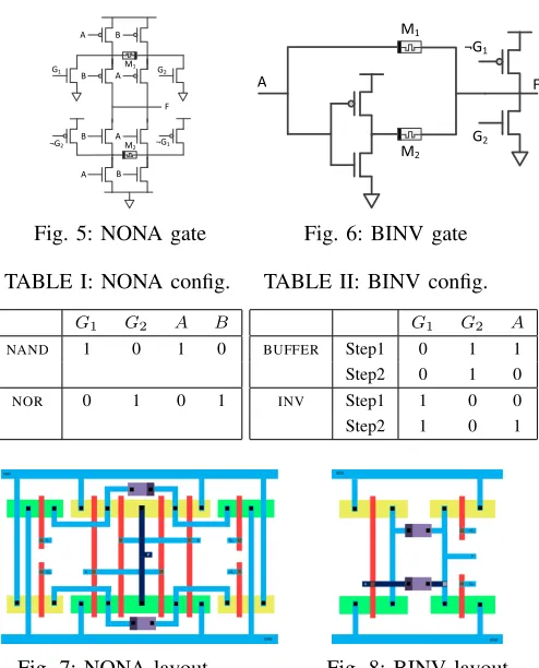
Fig. 5: NONA gate
щ'ϭ
'
Ϯ
DϮ
Dϭ
&
Fig. 6: BINV gate
TABLE I: NONA config.
G1 G2 A B
NAND 1 0 1 0
NOR 0 1 0 1
TABLE II: BINV config.
G1 G2 A
BUFFER Step1 0 1 1
Step2 0 1 0
INV Step1 1 0 0 Step2 1 0 1
Fig. 7: NONA layout Fig. 8: BINV layout
case, the SAT engine either will not find the correct key or will stick in an infinite loop.
III. IFA-PROOFOBFUSCATIONAPPROACH
Traditional logic encryption methods requires resynthesis to obfuscate the key-controlled elements. Since there is no powerful resynthesis tool for cyclic combinational circuits, it is essential to find an escape door. IC camouflaging is an advanced technique that combines the locking and ob-fuscation phases. Although state-of-the-arts IC camouflaging obfuscations (i.e. dummy contact [12] and doping-based [13] solutions) may be hard to discover in RE-based attacks, they are easily detectable in IFA. However, polymorphic CMOS-memristor gates are IFA-proof since changing of their behavior comes from modifying the resistance of their memristors after fabrication.
Thus, in this section, we propose two different polymor-phic CMOS-memristor gates that can be used to obfuscate combinational circuits. Each gate requires a configuration phase. However, the gates can be configured in parallel if they have independent logical inputs. Upon completion of the configuration phase, controlling signals are set to “0”.
A. NONA Design
TABLE III: Cyclic locking evaluation with dummy cycles
Bench SAT-based attack CycSAT-I attack CPU time #it CPU time #it
apex2 - Inf 0.04 4
apex4 - Inf 0.296 3
c432 - Inf - Inf
c499 0.072 8 0.06 3
c880 - Inf - Inf
c1355 - Inf 0.224 25
c1908 1.656 167 0.228 34
c2670 - Inf - Inf
c3540 - Inf - Inf
c5315 0.34 15 - Inf
c7552 - Inf - Inf
dalu 0.184 9 0.376 16
des - Inf 0.448 5
ex5 - Inf 0.116 11
ex1010 - Inf 0.488 3
i4 - Inf 0.02 3
i7 0.184 6 0.18 7
i8 0.396 7 0.42 8
i9 0.636 11 0.092 3
k2 - Inf - Inf
seq - Inf - Inf
as open-circuited (i.e. off.) On the other hand, to discharge a memristor, its resistance is decreased to the minimum resistance (Rmin.) In this case, the memristor is considered as
short-circuited (i.e. on.) If M1 is on whileM2 is off,NONA functions as NAND gate. On the contrary, ifM1 is off while M2 is on, NONA operates as NOR gate. The configuration procedure for NONA is shown in Table I. In configuration phase, the combination of the global controlling signals (i.e. G1 andG2) and the logical inputs (i.e. AandB) is used.
B. BINV Design
The proposed BUFFER-INV (BINV) gate is depicted in Fig. 6. If M1 is on while M2 is off, BINV works as a BUFFER. Contrariwise, BINV works as an INV. Table II shows a two-step configuration procedure for BINV. The combination of the global controlling signals (i.e.G1 andG2) and the logical input (i.e. A) is used to configure BINV.
Theorem 3. Inside foundry attack has the same complexity as reverse engineering based attack if the layout of the locked circuit is obfuscated by polymorphic memristor-CMOS gates.
Proof. Since polymorphic memristor-CMOS gates look ex-actly identical in circuit layout and charging/discharging of the memristors is done after the fabrication, an inside foundry attacker does not get more details from the connectivity information of the layout than an attacker that uses reverse engineering techniques to extract the layout.
IV. EXPERIMENTALRESULTS
In this section, first we demonstrate robustness of the proposed cyclic locking scheme against stat-of-the-art key-pruning attacks. Then, we depict the layouts of the proposed polymorphic gates and show the overhead.
TABLE IV: Cyclic locking evaluation with dummy/real cycles
Bench SAT-based attack CycSAT-I attack CPU time #it CPU time #it
apex2 - Inf - UNSAT
apex4 - Inf 0.332 3
c432 - Inf - UNSAT
c499 - Inf - UNSAT
c880 - Inf - UNSAT
c1355 - Inf - UNSAT
c1908 0.22 12 - UNSAT
c2670 - Inf - UNSAT
c3540 - Inf - UNSAT
c5315 - Inf - UNSAT
c7552 - Inf - UNSAT
dalu 0.68 24 - UNSAT
des - Inf - UNSAT
ex5 - Inf - UNSAT
ex1010 - Inf 0.5 3
i4 - Inf - UNSAT
i7 0.168 6 - UNSAT
i8 - Inf - UNSAT
i9 6.504 318 - UNSAT
k2 - Inf - UNSAT
seq - Inf - UNSAT
A. Cyclic Locking Evaluation
We apply our proposed cyclic locking scheme into acyclic combinational circuits of ISCAS ’85 and MCNC ’91. The original acyclic circuits are the same as the ones have been used in CycSAT paper [16]. For the first set of benchmarks, we intentionally lock each circuit with ten dummy cycles while for the second set, we intentionally add additional ten real cycles. Since the code for CycSAT-II is not available, we compare the decryption results between the original SAT-based and CycSAT-I attack on both sets of benchmarks.
As depicted in Table III, for benchmarks with only dummy cycles, CycSAT-I generally performs better than the original SAT-based attack. In cases withInf iterations, the SAT solver gets stuck in an infinite loop and cannot report any key.
As shown in Table IV, both attacking schemes have bad unlocking performance when real and dummy cycles co-exist in the benchmarks. However, the precise unlocking results between the original SAT-based and CycSAT-I attacks are somewhat different. The SAT-based attack gets trapped in an infinite loop when solving most of the locked circuits and sometimes even returns wrong keys (i.e. i7 and i9.) In a few benchmarks (i.e.c1908anddalu) the original SAT-based attack can return the correct key. This happens if the SAT solver is lucky enough to find strong DIPs to prevent non-combinational behavior from happening. Even with unlocking those benchmarks, the original SAT-based attack has less than
TABLE V: Polymorphic gates comparison
NAND NOR INV
Regular NONA Regular NONA Regular BINV Average Propagation Delay (ps) 9.25 10.03 9.97 10.42 6.03 6.12 Average Energy Consumption (nJ) 243.2 376.2 267.2 378.4 495.1 591.1 Number of Transistors / Memristors 4/0 12/2 4/0 12/2 2/0 4/2
(a) (b) (c)
Fig. 9: EDP and ED2P (a) NAND (b) NOR (c) INV
B. Polymorphic Gates Evaluation
Fig. 7 and 8 depict the layouts for the proposed polymorphic memrisor-CMOS gates (i.e. NONA and BINV.) As can be seen layout of different gates (i.e. NOR/NAND in NONA and BUFFER/INV in BINV) look exactly identical to anyone that has access to the layout, including third party engineers who manufacture the chip. Also, if the locking scheme is reliable, the layout of any IC that is partially implemented using the proposed polymorphic gates can even be publicly available.
In addition, Table V shows the overhead ofNONAandBINV compared with the regular gates in 45nm CMOS technology. The experiments are done in Cadence Virtuoso platform. Also, Fig. 9 shows Energy Delay Product (EDP) and Energy Delay-squared Product (ED2P) ofNAND,NOR, andINVunder polymorphic and regular gates. On average, propagation delay of NONA and BINV are 7% and 6% more than regular gates respectively. Also, energy consumption ofNONAandBINVare on average 40% and 20% more than regular gates respectively. Moreover, based on the fact that memristor can be imple-mented on top of the silicon layer, the size ofNONAandBINV are almost 3x and 2x larger in comparison with the regular gates. As an example, if an obfuscation scheme exchanges 5%, 10%, and 20% of the regular gates with polymorphic ones using an equal distribution of NONA andBINV, the total area overhead is less than 8%, 15%, and 30% respectively that seems reasonable for an obfuscation approach.
V. CONCLUSION
A functional IC can provide a lot of useful information to the attacker. Thus, she can misuse those information to unlock a locked circuit. This makes the SAT-based attack in particular or any key-pruning attack in general, a serious threat to chip protection. On the other hand, with the growing number of untrusted foundries, IFA becomes an escalating problem. In this paper, first we challenged the believe that cyclic combi-national circuits are useless by proposing cyclic combicombi-national locking. Then, we proposed polymorphic memrisor-CMOS gates to obfuscate the IC layout. Polymorphic gates look exactly identical for anyone who has access to the layout including inside foundry attackers. In this case, the design
goal is to have only one functional configuration while the other configurations are meaningless.
ACKNOWLEDGMENT
This work is partially supported by NSF under CNS-1441695, CNS-1651695, and CCF-1533656.
REFERENCES
[1] R. Torrance and D. James, “The state-of-the-art in semiconductor reverse engineer-ing,” InDesign Automation Conference (DAC), pp. 333-338, 2011.
[2] L. Chua, “Memristor - The missing circuit element,” In IEEE Transactions on Circuit Theory, Vol. 18, Issue 5, pp. 507-519, 1971.
[3] D. B. Strukov, G. S. Snider, D. R. Stewart, and R. S. Williams, “The missing memristor found,” InNature, Vol. 453, Issue 7191, pp. 80-83, 2008. [4] S. Kvatinsky, N. Wald, G. Satat, A. Kolodny, U. C. Weiser, and E. G. Friedman,
“MRL - Memristor ratioed logic,” In International Workshop on Cellular Nanoscale Networks and their Applications (CNNA), pp. 1-6, 2012.
[5] Y. Shen, A. Rezaei, and H. Zhou, “A comparative investigation of approximate attacks on logic encryptions,” InAsia and South Pacific Design Automation Conference (ASP-DAC), 2018.
[6] J. Rajendran, H. Zhang, C. Zhang, G. S. Rose, Y. Pino, O. Sinanoglu, and R. Karri, “Fault analysis-based logic encryption,” In IEEE Transactions on Computers, Vol. 64, Issue 2, pp. 410-424, 2015.
[7] F. Koushanfar, “Provably secure active IC metering techniques for piracy avoidance and digital rights management,” InIEEE Transactions on Information Forensics and Security, Vol. 7, Issue 1, pp. 51-63, 2012.
[8] J. Rajendran, M. Sam, O. Sinanoglu, and R. Karri, “Security analysis of integrated circuit camouflaging,” InACM Conference on Computer and Communications Security (CCS), pp. 709-720, 2013.
[9] P. Subramanyan, S. Ray, and S. Malik, “Evaluating the security of logic encryption algorithms,” InInternational Symposium on Hardware Oriented Security and Trust (HOST), pp. 137-143, 2015.
[10] Y. Xie and A. Srivastava, “Mitigating SAT attack on logic locking,” In Crypto-graphic Hardware and Embedded Systems (CHES), Lecture Notes in Computer Science, Vol. 9813, pp 127-146, Springer, 2016.
[11] M. Yasin, B. Mazumdar, J. J. V. Rajendran, and O. Sinanoglu, “SARLock: SAT attack resistant logic locking,” InInternational Symposium on Hardware Oriented Security and Trust (HOST), pp. 236-241, 2016.
[12] L. W. Chow, J. P. Baukus, and W. M. Clark Jr, “Integrated circuits protected against reverse engineering and method for fabricating the same using an apparent metal contact line terminating on field oxide,” US Patent 7,294,935, 2007. [13] G. T. Becker, F. Regazzoni, C. Paar, and W. P. Burleson, “Stealthy dopant-level
hardware trojans,” InCryptographic Hardware and Embedded Systems (CHES), Lecture Notes in Computer Science, Vol. 8086, pp. 197-214, Springer, 2013. [14] L. Sekanin, “Design methods for polymorphic digital circuits,” InDesign and
Diagnostics of Electronic Circuits and Systems Workshop (DDECS), pp.
145-150, 2005.
[15] K. Shamsi, M. Li, T. Meade, Z. Zhao, D. Z. Pan, and Y. Jin, “Cyclic obfuscation for creating SAT-unresolvable circuits,” In International Conference on Great
Lakes Symposium on VLSI (GLSVLSI), pp. 173-178, 2017.
[16] H. Zhou, R. Jiang, and S. Kong, “CycSAT: SAT-based attack on cyclic logic encryptions,” InInternational Conference on Computer-Aided Design (ICCAD), 2017.