Motion of Small Spherical Particles in an Arbitrary Oriented Cluster
Due to the Microwave Propagation
Aslan Nouri Moqadam, Ali Pourziad*, and Saeid Nikmehr
Abstract—The electromagnetic (EM) waves influence substances involved in the propagation medium which leads to deviation or modification. Atomic stresses and strains caused by EM radiation make electromagnetic waves able to stir small particles by exertion of Lorentz force on them which is employed to deviate particles in this paper. The particles are considered as millimeter and micrometer-sized spheres with random electrical properties. Generalized Multi-Particle Mie theory (GMMT) is used to calculate scattering parameters such as Radar Cross Section for aggregates of arbitrarily oriented particles. The direction of motion caused by exerted Lorentz force on particles is accurately obtained in terms of Discrete Dipole Approximation (DDA). A bulk model based on Effective Medium Theory is designed to analyze the scattering parameters of particles, much smaller than incident wavelength. Application of this model is validated by several simulations. The profile of arbitrary incident wave and its amplitude and polarization effects on deviation are investigated, respectively. Numerical results are derived for various arbitrary orientations and different electromagnetic conditions.
1. INTRODUCTION
Scattering of EM waves and their applications are among the most interesting topics in communicational literature. Deviation and modification power of EM waves on much smaller particles tha incident wavelength innovated a new era in the ISM applications. Modification and elimination of cancer tumors in radiotherapy through microwaves besides environmental protection from floating dust particles are the most noticeable applications in medical and industrial societies. Satellite communications and microwave propagation through the atmosphere are also involved with floating atmosphere particles such as rain drops which deviate propagating wave from its main path causing communication loss. Detailed scattering properties of particles in a cluster give incredible information about material, motion and orientation of particles. The reason behind cluster investigation is that small particles are available in different clusters in nature, and accordingly, scattering parameters analysis of an isolated extra small particle is not practical. So, EM waves are widely employed in ISM applications leading to electromagnetic techniques in healthcare and environmental protection.
EM waves facing discontinuities or waves propagating through anisotropic medium deviate from their original paths [1]. This phenomenon, called scattering, is an atomic event where positive and negative charges are replaced due to EM wave, so this movement leads to an oscillation. This atomic oscillation tends to radiate, and the primary wave transforms to multiple waves, propagating in different paths [2].
Several techniques were employed to analyze multiple scatterings by arbitrarily shaped particles. Scattering by a single homogenous sphere with the size comparable to wavelength known as the Mie Theory is the basic theory for spherical particles [2]. EM scattering by aggregates of spheres with
Received 6 April 2017, Accepted 13 June 2017, Scheduled 20 June 2017
* Corresponding author: Ali Pourziad ([email protected]).
the help of generalized Multi-particle Mie Theory (GMMT) was studied in late 20s [3]. That is also applicable to variously shaped small particles [4]. Transition Matrix provides expressions for scattering by random shapes such as finite cylinders and spheres, which has been derived for ensemble of spheres by Mishchenko et al. [5]. Ryleigh and discrete dipole approximation (DDA) for EM scattering from small particles compared to wavelength were also employed to study multiple scattering [6].
Environmental application of multiple scatterings were discussed in various papers. Expressions for attenuation and phase shift coefficients for a medium with sand and dust have been demonstrated recently [7]. Radiation pressure of the Sun on fluffy dust particles was calculated by Kimura et al. where the reaction of sun rays propagation through fluffy dust particles and radiation pressure on them were considered [8]. These studies are mostly based on optical frequencies, and the common case is motion of particles in the presence of laser beam [9]. Particles behaviors at microwave frequencies have rarely been discussed in literature and almost ignored.
In this paper, microwave propagation in a random medium and scattering properties of particles which are considered as spheres are investigated by the help of multiple scattering analysis methods. The absolute value and direction of forces exerted on particles are demonstrated in detail. So the motion and movement of particles due to electromagnetic forces exerted on particles can be predicted. The influence of wave polarization and amplitude besides different wave types on the amount and direction of exerted forces will be discussed in later sections. Concerning these effects, proper wave features can be chosen to deviate the spherical particles consciously according to desired application.
2. STATEMENT OF THE PROBLEM
Suppose a system of L isotropic and homogenous spheres confined in a finite volume with specific radius al where l = 1,2,3, . . . , L and known electrical permittivity εl in which the spheres are arbitrarily oriented. Scattering cross section of the spheres is calculated through a GMMT based algorithm coded by MATLAB software. The purpose of this paper is to deviate these spheres and predict the direction of deviation. The absolute value of forces exerted on spheres besides direction of deviation will be shown in later sections. Some hints about conscious deviation proposed in this paper are suitable for environmental and medical applications.
2.1. Generalized Multi-Particle Mie Theory
Mie Theory is the exact solution for scattering of an isotropic, homogenous sphere lightened by an electromagnetic plane wave. GMMT is not limited to a single sphere, so multi-sphere system can be analyzed in this way. Isolated spheres besides spheres interaction in scattering should be noticed in GMMT [10]. In the Cartesian coordinate system originated inlth sphere center, incident wave on each sphere is the sum of main excitation wave and the wave scattered by other spheres. Vector spherical wave functions (VSWF) are employed to expand scattered, internal and incident electromagnetic fields. Expansion coefficient in each term of GMMT can be calculated based on classical Mie coefficients [1]:
Eincl =−E0
∞
n=1
n
m=−n in+1
plmnN¯mn(1)l+qlmnM¯mn(1)l
,
Escal =E0
∞
n=1
n
m=−n in+1
almnN¯mn(3)l+blmnM¯mn(3)l
Eintl =−E0
∞
n=1
n
m=−n in+1
dlmnN¯mn(1)l,int+clmnM¯mn(1)l,int
(1)
where: ¯
Mmn(l) = [ˆeθiπmn(θ)−eˆϕτmn(θ)]zn(l)(ρ)×exp (imϕ), ¯
Nmn(l) = ⎧ ⎪ ⎨ ⎪
⎩eˆrn(n+ 1)P
m
n (cosθ)z
(l)
n (ρ)
ρ + [ˆeθτmn(θ) + ˆeϕiπmn(θ)]
ρz(nl)(ρ)
ρ ⎫ ⎪ ⎬ ⎪
Without loss of generality, an incident EM plane wave propagating in positivez direction, with linear polarization defined by βp angle is considered in this paper to illuminate the multi-sphere system. For
mentioned type of incident wave, expansion coefficients have simple form [3]: qmnl =−exp
ikZl
mδ|m|,1
√
2n+ 1
2 exp (−imβp), plmn= exp
ikZl
mδ|m|,1
√
2n+ 1
2 exp (−imβp)
(3)
At the surface of the lth dielectric sphere because there are not any magnetic or electric charges, internal and external EM fields should cancel each other, so the boundary condition at the surface is demonstrated below:
Ei+Es−EI׈r=Hi+Hs−HI×rˆ= 0 (4)
Surface boundary conditions satisfies Eq. (4) in terms of EM fields’ expansions in spherical coordinates as Eq. (1) GMMT coefficients are obtained as a function of classical Mie Theory coefficients: almn =alnplmn, blmn =blnqlmn, clmn=clnqlmn, dlmn =dlnplmn (5) 2.2. Translational Addition Theorem
Notice that incident EM field on thelth sphere is the sum of primary excitation field and the EM field scattered by other spheres. Hence, to obtain scattering coefficients of the lth sphere, the scattered field of rest spheres should be translated to the new coordinate system originated in the center of the lth sphere. This event is possible by the help of Translational Addition Theorem [11]. In this method, scattered field of an isolated sphere will be considered as incident field to mentioned origin sphere, so outward VSWF turns to inward one.
¯
Mmn(3)(l) =
∞ ν=0 ν μ=−ν
Amnμν (l, j)Mμν(1)(j) +BμνmnNμν(1)(j)
,
¯
Nmn(3)(l) =
∞ ν=0 ν μ=−ν
Bμνmn(l, j)Mμν(1)(j) +Amnμν Nμν(1)(j)
(6)
Eq. (6) demonstrates the outward VSWF as the sum of inward VSWF in terms of translational coefficients. Amnμν andBμνmn are mentioned translational coefficients [12]:
Amnμν = (−1)μiν−n 2ν+ 1 2ν(2ν+ 1)
n+ν
p=|n−ν|
(−i)p×[n(n+ 1) +ν(ν+ 1)−p(p+ 1)]
×a(m, n,−μ, ν, p)hp(1)(kdj,l)×Ppm−μ(cosθj,l) exp [i(m−μ)φj,l]
Bμνmn= (−1)μiν−n 2ν+ 1 2ν(2ν+ 1)
n+ν
p=|n−ν|
(−i)p×b(m, n,−μ, ν, p, p−1)h(1)p (kdj,l)
×Ppm−μ(cosθj,l) exp [i(m−μ)φj,l]
(7)
As seen in Eq. (7), it is obvious that translational coefficients are functions of sphere’s coordinates; dj,l is the distance between two arbitrary spheres; θj,l and ϕj,l are differential elevation and azimuth
angles of two mentioned spheres. To achieve the absolute value of translational coefficients, Gaunt Coefficients should be calculated primarily.
2.3. Gaunt Coefficients
expressions are correlated functions, so here a(m, n, μ, ν, p) results will be illustrated in table which leads to obtaining b(m, n, μ, ν, p, p−1) results, subsequently.
a(m, n, μ, ν, p) = 2p+ 1 2
(p−m−μ)! (p+m+μ)! ×
1
−1
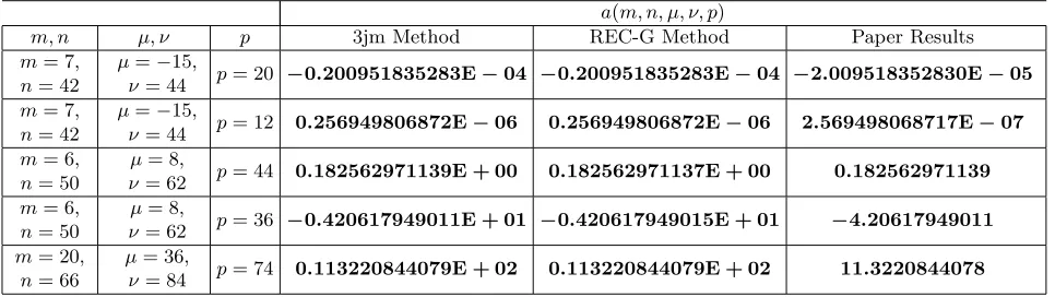
Pnm(x)Pνμ(x)Ppm+μ(x)dx (8) Table 1 shows the comparison between 3jm method, REC-G recursive theme and designed method in this paper [13]. Results show extremely good agreement that proves efficiency of the algorithm in this paper.
Table 1. Calculation of gaunt coefficients.
a(m, n, μ, ν, p)
m, n μ, ν p 3jm Method REC-G Method Paper Results
m= 7, n= 42
μ=−15,
ν= 44 p= 20 −0.200951835283E−04 −0.200951835283E−04 −2.009518352830E−05 m= 7,
n= 42
μ=−15,
ν= 44 p= 12 0.256949806872E−06 0.256949806872E−06 2.569498068717E−07 m= 6,
n= 50
μ= 8,
ν= 62 p= 44 0.182562971139E + 00 0.182562971137E + 00 0.182562971139 m= 6,
n= 50
μ= 8,
ν= 62 p= 36 −0.420617949011E + 01 −0.420617949015E + 01 −4.20617949011 m= 20,
n= 66
μ= 36,
ν= 84 p= 74 0.113220844079E + 02 0.113220844079E + 02 11.3220844078
2.4. Amplitude Scattering Matrix
Amplitude scattering matrix demonstrates relation between scattered and incident EM field components in both parallel and perpendicular polarizations [3]. For a plane wave propagating in positivezdirection in Cartesian coordinates scattering matrix has the form below [12]:
Esca E⊥sca
= e
jk(r−z)
jkr S2 S3 S4 S1 Einc E⊥inc (9) Scattering intensities for different elevation (θ) and azimuth angles (ϕ) are defined in terms of the scattering matrix elements:
i11(θ,0◦) =S1(90◦)(θ,0◦)2, i22(θ,0◦) =S2(0◦)(θ,0◦)2 (10) Scattering intensities shown in Eq. (10) are in the cross-polarization with each other. According to GMMT scattering coefficients amplitude matrix elements can be calculated directly. Amplitude scattering matrix provides significant information about scattering properties of the multi-sphere system [12]. Radar Cross Section (RCS) will be obtained directly in terms of opposite scattering intensities [14]:
σV V = λ
2
4π2i11 σHH = λ2
4π2i22 (11)
Differential Radar Cross Section is the average of differential cross sections in vertical and horizontal polarizations [14]:
σsca = λ 2
8π2(i11+i22) (12)
2.5. Bulk Model for Particles Much Smaller Than Wavelength
of x 1 Mie Theory’s accuracy decreases, so in this situation Bulk model will be helpful for getting accurate results. Since GMMT is the generalization of classical Mie theory, bulk model is applicable to GMMT, similarly. Bulk model employed in this paper is based on Effective Medium Theory where small particles compared to wavelength are considered as electrical dipoles [15]. Aggregates of these dipoles which are specifically oriented can be modeled as a coarser particle, and in later discussion, it will be illustrated that specific orientation is not necessary, and random orientation can be applied to this approximation. Bulk model analysis illustrates small particles as spheres with the electrical permittivity ofεr specifically oriented in a lattice which altogether are modeled by a new sphere coarser
than them withεeff confined in a medium introduced byεH which is illuminated by a plane wave. The
expression for εeff follows the effective medium theory, where [15]:
εeff =εH +
3f εH
εr−εH
εr+ 2εH
1−f
εr−εH
εr+ 2εH
(13)
In Eq. (13), f is the fraction volume occupied by tiny particles. In terms of the discussed bulk model, GMMT application is validated for particles much smaller than incident wavelength.
3. EXERTED FORCES ON SPHERICAL PARTICLES
This section demonstrates the absolute value of exerted force on the particles besides the direction of motion. EM exerted force value is calculated according to Discrete Dipole Approximation [6].
3.1. Discrete Dipole Approximation
As discussed before, particles much smaller than wavelength can be considered as electrical dipoles. Each particle is defined by a position vector rl and electrical polarization αl, so the dipole momentum can be directly obtained by dipole polarization [6]:
Pl=αlEl (14)
Here El is the electric field on thelth particle and defined by expression below:
El=Einc,l−
k=l
AlkPk Alk= exp(ikrlk) rlk
k2(ˆrlkrˆlk−I3) + ikrlk−1 r2
lk
(3ˆrlkrˆlk−I3)
(15) Similar to translational addition theorem Alk translates scattered field by rest spheres on the lth
one.
3.2. Electromagnetic Force Exerted on a Dipole
To derive the EM force exerted on a dipole, first electrical polarization of dipole should be calculated.
A-1 term method is a proper solution to achieve electrical polarization in terms of Mie scattering coefficient [16]. In this method, polarization can be obtained directly by first Mie scattering coefficient a1 which suits GMMT.
αl =i32ka13 (16)
In Eq. (16), k is propagation constant in free space. By substitution of Eq. (16) into Eq. (14), dipole momentum will be calculated. The electromagnetic force exerted on a dipole due to EM field is a function of electrical and magnetic field as below [17]:
F = (p· ∇)E+p×(∇ ×E) + d
dt(p×B) (17)
By neglecting the effect of magnetic field according to smaller amplitude than electrical field which is a reasonable approximation, Eq. (17) will have a simple form:
F =
i
As seen in Eq. (18), gradient operates on a vector, then result will be a 3×3 dyadic which illustrates each component of force due to any component of electrical field. In this way, all the possible conditions have been considered for anisotropic scattering medium.
3.3. Electrical Properties of Particles
Particles are considered as dielectric spheres in this paper, so dielectric permittivity, dielectric loss and electrical conductivity are the main electrical properties of the spherical particles. Random quantities are considered for the particles’ dielectric permittivity and electrical conductivity. The programmed algorithm is not limited to the particles’ material and their orientation. It is a comprehensive algorithm for all types of materials and orientations. As an example, electrical properties of mentioned particles are demonstrated through several tables in later sections.
4. NUMERICAL RESULTS
This section provides numerical results discussed before about particles. Radar cross section, bulk model efficiency and forces exerted on particles are the parameters which will be calculated in the next sections. Two different conditions are considered to simulate with particles’ electrical properties at different microwave frequencies. Both simulations have been verified by bulk model to analyze smaller particles than wavelength. Operating system is Core i5 M460, 2.53 GHz CPU with 4GB DDR 3 RAM memory. Software package is MATLAB besides Computer Simulation Technology (CST). Designed algorithm to calculate RCS and exerted force programmed by MATLAB and bulk model analysis are done by CST.
Table 2 demonstrates the configuration of first simulation where particles are millimeter-sized. For a practical viewpoint, electrical properties of particles are considered similar to dust particles [18] for moisture content of 0.079 and can be generalized for any types of particles. The efficiency of programmed algorithm will be discussed in later sections.
Table 2. Configuration of first simulation.
Number of particles 7
Electrical permittivity (εr) 4−j0.7
Electrical Conductivity (σ)
-Radius 7 (mm)
Orientation Random
Frequency 10 GHz
Incident wave polarization βP 0 (x-polarized)
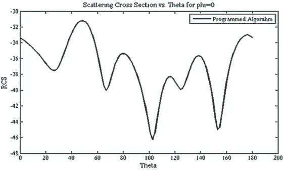
Radar cross section for mentioned simulation is calculated through Eq. (12). RCS parameter is illustrated vs. elevation angle (θ) at a fixed azimuth angle ϕ= 0◦. In terms of RCS results, scattering parameters for aggregate of particles vs. different elevation angles can be extracted. Fig. 1 illustrates the RCS of the 7 arbitrarily oriented spherical particles considered as spheres defined in Table 2 illuminating by a linear polarized plane wave.
This configuration is designed for millimeter-sized particles. According to incident wave frequency, these particles are not considered much smaller than wavelength. Bulk model analysis for smaller particles should be employed.
Effective medium theory is employed to apply Mie theory for much smaller particles than wavelength. Fig. 2 shows an example of effective medium theory in which specifically oriented smaller particles are modeled by a coarser spherical particle with effective permittivity calculated by Eq. (13). Table 3 demonstrates the configuration for bulk model analysis.
Figure 1. Radar cross section [dB] vs. elevation angle [Degrees].
(a) (b)
Figure 2. Bulk model analysis. (a) Original model. (b) Bulk model.
Table 3. Configuration of bulk model analysis.
Number of particles 13
Electrical permittivity (εr) 4
Electrical Conductivity (σ)
-Particle Radius 1 (mm)
Distance between particles 3 (mm)
Bulk model radius 7 (mm)
Effective permittivity (εeff) 1.1
Frequency 10 GHz
Incident wave polarization βP 0 (x-polarized)
RCSs of two mentioned structures. In later sections, the effect of electrical conductivity will be discussed. RCS comparison is done vs. elevation angle at fixed azimuth angles (ϕ= 0◦, ϕ= 90◦).
(a) (b)
Figure 3. RCS [dB] comparison of original structure vs. bulk model. (a)ϕ= 0◦. (b)ϕ= 90◦.
(a) (b)
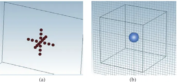
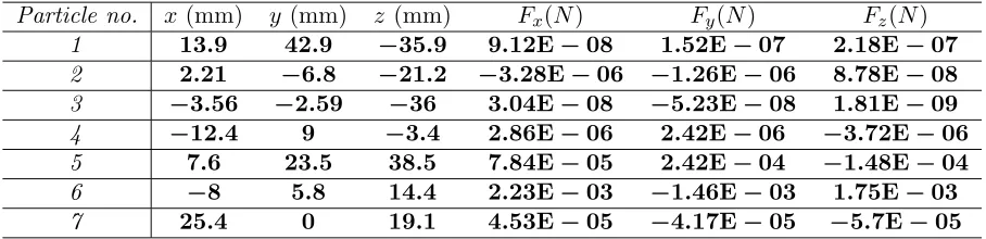
Figure 4. Orientation of particles. (a) Distribution. (b) Direction of motion. Table 4. Components of exerted force.
Particle no. x(mm) y (mm) z (mm) Fx(N) Fy(N) Fz(N)
1 13.9 42.9 −35.9 9.12E−08 1.52E−07 2.18E−07
2 2.21 −6.8 −21.2 −3.28E−06 −1.26E−06 8.78E−08
3 −3.56 −2.59 −36 3.04E−08 −5.23E−08 1.81E−09
4 −12.4 9 −3.4 2.86E−06 2.42E−06 −3.72E−06
5 7.6 23.5 38.5 7.84E−05 2.42E−04 −1.48E−04
6 −8 5.8 14.4 2.23E−03 −1.46E−03 1.75E−03
7 25.4 0 19.1 4.53E−05 −4.17E−05 −5.7E−05
the orientation of particles. Accordingly, Fig. 4(b) demonstrates direction of Lorentz force exerted on particles. Positions of particles and component of forces exerted on particles are demonstrated in Table 4.
Figure 5. Radar cross section [dB] vs. elevation angle [Degree].
field on dipole position, then the total force exerted on bulk particle also stimulates smaller particles. Millimeter-sized particles’ motion due to microwave propagation is discussed in last section. Now a new simulation for micrometer-sized particles will be considered, and it is a practical one for environmental protection.
Figure 5 illustrates RCS of configuration in Table 5 vs. elevation angle (θ) at a fixed azimuth angle ϕ= 0◦ based on GMMT.
Similarly, bulk model analysis as in Fig. 6 is employed for micrometer-sized particles where configurations of original and modeled particles are shown in Table 6 in detail.
Table 5. Configuration of second simulation.
Number of particles 10
Electrical permittivity (εr) 3.8−j0.9
Electrical Conductivity (σ) 0.1 (s/m)
Radius 1 (mm)
Orientation Random
Frequency 20 GHz
Incident wave polarization βP 0 (x-polarized)
Table 6. Configuration of bulk model analysis.
Number of particles 19
Electrical permittivity (εr) 3.8
Electrical Conductivity (σ) 0.1 (s/m)
Particle Radius 0.1 (mm)
Distance between particles 0.3 (mm)
Bulk model radius 1 (mm)
Effective permittivity (εeff) 1.1
Frequency 20 GHz
(a) (b)
Figure 6. Bulk model analysis. (a) Original model. (b) Bulk model.
(a) (b)
Figure 7. RCS [dB] comparison of original structure vs. bulk model for (a)ϕ= 0◦, (b)ϕ= 90◦.
The next step is to validate effective medium theory involvement in multi-particle scattering by CST simulation of original and modeled structure at 20 GHz frequency. Electrical conductivity is also involved in improving the reliability of bulk model analysis. Results show better agreement than before when conductivity of 0.1 (s/m) is considered. Consuming of conductivity is a realistic definition of natural particles in practice.
Simulation done by CST confirms the prediction of the writers in conductivity involvement which leads to more accurate results. Fig. 7 compares the RCS of original model with the conductive bulk model for two different azimuth angles at 20 GHz, and the results show great agreement by considering electrical conductivity for the desired bulk model. As discussed before, specific and regular orientation in bulk model analysis is not a necessity. Fig. 6 demonstrates a regular orientation, but anisotropic or arbitrary orientation is also simulated in this paper.
Configuration of Fig. 8 is demonstrated in Table 7 in detail. Despite primary simulations in this condition particles in original model are arbitrary oriented, so there is not any regular form in orientation. Distance between particles is random. Results shown in later parts claim that reliability of bulk model analysis is a direct function of fraction volume, not orientation, which means that the more particles are involved in specific medium, the better results occur for bulk model analysis. So, accuracy of approximation is obedient of fraction volume ratio. RCS calculations are illustrated in Fig. 9(a) and Fig. 9(b).
(a) (b)
Figure 8. Arbitrary bulk model analysis. (a) Original model. (b) Bulk model.
(a) (b)
Figure 9. RCS [dB] comparison of original arbitrary structure vs. bulk model for (a) ϕ = 0◦, (b) ϕ= 90◦.
Table 7. Configuration of bulk model analysis.
Number of particles 28
Electrical permittivity (εr) 3.8
Electrical Conductivity (σ) 0.1 (s/m)
Particle Radius 0.1 (mm)
Distance between particles random
Bulk model radius 1 (mm)
Effective permittivity (εeff) 1.1
Frequency 20 GHz
Incident wave polarization βP 0 (x-polarized)
(a) (b)
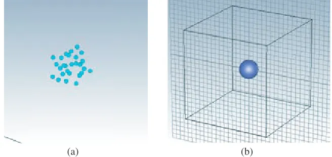
Figure 10. Orientation of particles. (a) Distribution. (b) Motion of direction.
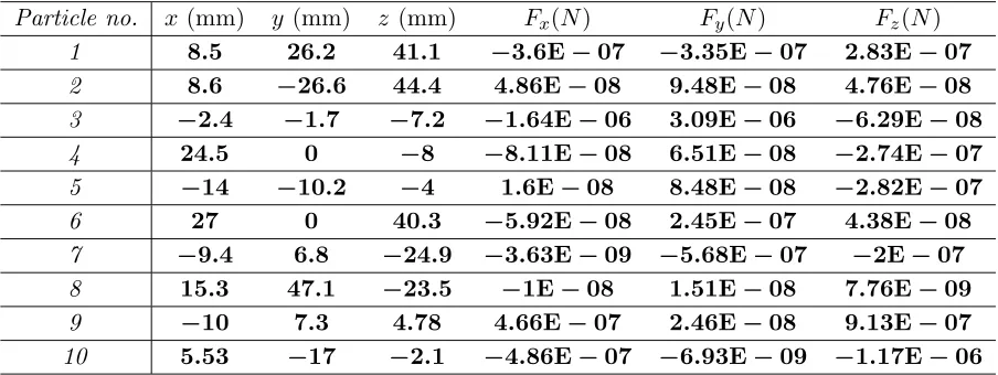
Table 8. Components of exerted force.
Particle no. x(mm) y (mm) z (mm) Fx(N) Fy(N) Fz(N)
1 8.5 26.2 41.1 −3.6E−07 −3.35E−07 2.83E−07
2 8.6 −26.6 44.4 4.86E−08 9.48E−08 4.76E−08
3 −2.4 −1.7 −7.2 −1.64E−06 3.09E−06 −6.29E−08
4 24.5 0 −8 −8.11E−08 6.51E−08 −2.74E−07
5 −14 −10.2 −4 1.6E−08 8.48E−08 −2.82E−07
6 27 0 40.3 −5.92E−08 2.45E−07 4.38E−08
7 −9.4 6.8 −24.9 −3.63E−09 −5.68E−07 −2E−07
8 15.3 47.1 −23.5 −1E−08 1.51E−08 7.76E−09
9 −10 7.3 4.78 4.66E−07 2.46E−08 9.13E−07
10 5.53 −17 −2.1 −4.86E−07 −6.93E−09 −1.17E−06
5. INCIDENT WAVE EFFECT ON EXERTED FORCE
5.1. Wave Amplitude and Polarization
Simulation in primary sections, all are done by a normalized incident wave illumination multi-particle system. Suppose that amplitude of incident wave is not normalized, then by Eq. (1) it can be understood that E0 is a fixed parameter, and it is not a matter of orientation or particle properties. In terms of Eq. (18) it is obvious that amplitude of incident wave has direct effect on absolute value of exerted force but not direction of motion.
Back to configuration of Table 5 for orientation and properties of particles, polarization of incident wave can be discussed by change of polarization angleβP. As an example,βP = 45◦ is simulated in this
paper. Orientation and configuration is the same as previous simulation, and new simulation is devoted just to investigate polarization effect. Table 9 demonstrates components of exerted force as polarization changes.
5.2. Wave Types
Table 9. Components of exerted force.
Particle no. x(mm) y(mm) z(mm) Fx Fy Fz
1 8.5 26.2 41.1 −1.84E−07 3.27E−07 −1.62E−07
2 8.6 −26.6 44.4 −4.51E−07 3.03E−07 3.11E−07
3 −2.4 −1.7 −7.2 −1.79E−05 −1.07E−05 8.99E−06
4 24.5 0 −8 −1.04E−08 5.94E−07 6.89E−08
5 −14 −10.2 −4 −3.1E−07 7.52E−07 −8.84E−07
6 27 0 40.3 −1.3E−06 5.88E−07 −9.13E−07
7 −9.4 6.8 −24.9 −2.38E−06 −9.43E−08 9.02E−07
8 15.3 47.1 −23.5 −2.11E−07 −1.32E−08 −1.92E−08
9 −10 7.3 4.78 −1.12E−06 8.59E−07 −3.41E−06
10 5.53 −17 −2.1 −3.98E−08 −1.25E−07 6.52E−07
below:
pmn=
i 2π 0 π 0 ¯
Einc·Nmn(1)∗(ρ, θ, ϕ) sinθdθdϕ
E0in(n−m)!
(n+m)!(2n+ 1) 2π 0 π 0 N(1)
mn(ρ, θ, ϕ)
2
sinθdθdϕ
qmn=
i 2π 0 π 0 ¯
Einc·Mmn(1)∗(ρ, θ, ϕ) sinθdθdϕ
E0in(n−m)!
(n+m)!(2n+ 1) 2π 0 π 0 M(1)
mn(ρ, θ, ϕ)
2
sinθdθdϕ
(19)
For any type of incident wave expansion coefficients will be obtained properly. Procedure for linear plane wave should be followed to calculate exerted force on particles by other types of incident wave. 6. EFFICIENCY OF PROGRAMMED ALGORITHM
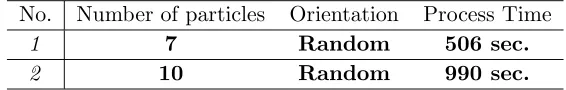
The designed algorithm is proposed to calculate RCS and exerted force, merely. The process time of designed two simulations is demonstrated in Table 10 accurately. The more complex the structure is, the more time the process is needed.
Table 10. Process time of programmed algorithm.
No. Number of particles Orientation Process Time
1 7 Random 506 sec.
2 10 Random 990 sec.
7. CONCLUSION
through soil electrical properties applied to spherical particles. Mie theory and DDA are employed to analyze multi-particle scattering problem for particles with sizes comparable to wavelength of incident wave. For particle much smaller than incident wavelength, a bulk model based on effective medium theory is designed and validated by several simulations done by CST. The last section is devoted to discussing effects of wave amplitude, polarization and wave types on deviation of particles.
REFERENCES
1. Tsang, L., J. A. Kong, and K.-H. Ding, Scattering of Electromagnetic Waves, Theories and Applications, Vol. 27, John Wiley & Sons, 2004.
2. Ishimaru, A., Electromagnetic Wave Propagation, Radiation, and Scattering, Prentice-Hall, 1991. 3. Xu, Y.-L., “Electromagnetic scattering by an aggregate of spheres,”Applied Optics, Vol. 34, 4573–
4588, 1995.
4. Xu, Y.-L., “Scattering Mueller matrix of an ensemble of variously shaped small particles,” JOSA A, Vol. 20, 2093–2105, 2003.
5. Mishchenko, M. I., L. D. Travis, and D. W. Mackowski, “T-matrix computations of light scattering by nonspherical particles: A review,”Journal of Quantitative Spectroscopy and Radiative Transfer, Vol. 55, 535–575, 1996.
6. Draine, B. T. and P. J. Flatau, “Discrete-dipole approximation for scattering calculations,” JOSA A, Vol. 11, 1491–1499, 1994.
7. Dong, Q.-F., Y.-L. Li, J.-D. Xu, H. Zhang, and M.-J. Wang, “Effect of sand and dust storms on microwave propagation,”IEEE Transactions on Antennas and Propagation, Vol. 61, 910–916, 2013. 8. Kimura, H., H. Okamoto, and T. Mukai, “Radiation pressure and the Poynting-Robertson effect
for fluffy dust particles,” Icarus, Vol. 157, 349–361, 2002.
9. Kawata, S. and T. Sugiura, “Movement of micrometer-sized particles in the evanescent field of a laser beam,”Optics Letters, Vol. 17, 772–774, 1992.
10. Xu, Y.-L. and B. ˚A. Gustafson, “A generalized multiparticle Mie-solution: Further experimental verification,”Journal of Quantitative Spectroscopy and Radiative Transfer, Vol. 70, 395–419, 2001. 11. Dufva, T. J., J. Sarvas, and J. C.-E. Sten, “Unified derivation of the translational addition theorems for the spherical scalar and vector wave functions,”Progress In Electromagnetics Research B, Vol. 4, 79–99, 2008.
12. Xu, Y.-L., “Electromagnetic scattering by an aggregate of spheres: Far field,” Applied Optics, Vol. 36, 9496–9508, 1997.
13. Xu, Y.-L., “Efficient evaluation of vector translation coefficients in multiparticle light-scattering theories,” Journal of Computational Physics, Vol. 139, 137–165, 1998.
14. Hahn, D. W., “Light scattering theory,” Department of Mechanical and Aerospace Engineering, Florida, 2006.
15. Naseem, A., “Computation and analysis of effective permittivity of thin film nanostructures: An effective medium perspective,” University of Toledo, 2010.
16. Okamoto, H., “Light scattering by clusters: The al-term method,”Optical Review, Vol. 2, 407–412, 1995.
17. Novotny, L. and B. Hecht, Principles of Nano-optics, Cambridge University Press, 2012.
![Figure 5. Radar cross section [dB] vs. elevation angle [Degree].](https://thumb-us.123doks.com/thumbv2/123dok_us/1882921.1245467/9.612.182.432.597.728/figure-radar-cross-section-db-elevation-angle-degree.webp)