“A Smulation Based On 12-Pulse Vsc Statcom With Harmonic Filter
Reduced Harmonics And Voltage Flickers ”
K Rajesh
(Assistant Professor, M Tech, Department of Electrical and Electronics Engineering, Brilliant Institute of Engineering & Technology (Telangana), India.)
ABSTRACT: Voltage flicker is considered as one of the most severe power quality problems (especially in loads like electrical arc furnaces), voltage flicker effect on the voltage quality. Due to the latest achievements in the semiconductors industry and consequently the emergence of the compensators based on voltage source converters, FACTS devices have been gradually noticed to be used for voltage flicker compensation. In this thesis voltage flicker mitigation has been investigated for static synchronous compensator (STATCOM). For this purpose a two-bus system connected with STATCOM is used. Initially a 6-pulse voltage source converter STATCOM is used to compensate for the voltage flicker. In this case injection of harmonics into the system caused some problems which are later overcome by using 12-pulse voltage source converter STATCOM and harmonic filter. All the simulations have been performed on the MATLAB SIMULINK software. The obtained results show that STATCOM is very efficient and effective for the flicker compensation.
INTRODUCTION: Power quality is the combination of voltage quality and current quality, thus power quality is concerned with deviations of voltage and or current from ideal. Power quality (PQ) related issues are of most concern nowadays. The widespread use of electronic equipment and Electrical equipment susceptible to power quality or more appropriately to lack of power quality would fall within a seemingly boundless domain. All electrical devices are prone to failure or malfunction when exposed to one or more power quality problems. The electrical device might be an electric motor, a transformer, a generator, a computer, a printer, communication equipment, or a household appliance.
All of these devices and others react adversely to power quality issues, depending on the severity of problems. A simpler and perhaps more concise definition might state: “Power quality is a set of
electrical boundaries that allows a piece of equipment to function in its intended manner without significant loss of performance or life expectancy.” This definition embraces two things that we demand from an electrical device: performance and life expectancy. Any power-related problem that compromises either attribute is a power quality concern. In light of this definition of power quality, this chapter provides an introduction to the more common power quality problems.
Power quality problems:
1. Voltage sag (dip) 2. Voltage swell 3. Harmonics 4. Interruptions 5. Voltage spike 6. Noise
7. Voltage unbalance 8. Distortions 9. Transients 10. Voltage flicker
FLEXIBLE AC TRANSMISSION SYSTEM: Flexible AC Transmission Systems, called FACTS, got in the recent years a well-known term for higher controllability in power systems by means of power electronic devices. Several FACTS devices, have been introduced for various applications worldwide. A number of new types of devices are in the stage of being introduced in practice.
In most of the applications the controllability is used to avoid cost intensive or landscape requiring extensions of power systems, for instance like upgrades or additions of substations and power lines. FACTS devices provide a better adaptation to varying operational conditions and improve the usage of existing installations. The basic applications of FACTS devices are:
• Power flow control,
• Increase of transmission capability, • Voltage control,
• Reactive power compensation, • Stability improvement,
• Power quality improvement, • Flicker mitigation,
Classification of FACTS devices:
The development of FACTS devices has started with the growing capabilities of power electronic components. Devices for high power levels have been made available in converters for high and even highest voltage levels. The overall starting points are network elements influencing the reactive power or the impedance of a part of the power system. Figure 2.1 shows
a number of basic devices separated into the conventional ones and the FACTS devices. For the FACTS side the taxonomy in terms of 'dynamic' and 'static' needs some explanation. The term 'dynamic' is used to express the fast controllability of FACTS-devices provided by the power electronics. This is one of the main differentiation factors from the conventional devices. The term 'static' means that the devices have no moving parts like mechanical switches
to perform the dynamic controllability.
Therefore most of the FACTS devices can equally be static and dynamic.
Fig. 2.1 Overview of major FACTS devices
(inverter side) becomes larger than that of the secondary voltage (system side), the current passes the AC power system through the leakage reactance (X) of the transformer, and inverter generates reactive power for the power system (capacitive case). If the secondary voltage of the transformer (inverter side) becomes larger than the primary voltage (system side), the reactive current passes from AC system to the inverter and inverter observes reactive power (inductive case).This current is calculated as follows: X U U I acs− vsi = (1) where Uacs and Uvsi are the ac power system and VSI voltages, respectively and X is the leakage reactance of the transformer. In the case of equal secondary and primary voltage, interchange of the reactive power is equal to zero.
COMPENSATION SYSTEM:
1. A two bus power system connected with STATCOM: In this project a two bus system is considered to investigate the voltage flicker compensation using STATCOM. This configuration block diagram is illustrated in fig: 3.2 which consist of 3Ø programmable voltage source [1-23] and STATCOM. The voltage oscillation is produced by the programmable voltage source which is connected to the main bus-bar, by specifying the amplitude of modulation the signal increments and decrements with respect to unit value. Operating conditions and parameters are represented in the Appendix. 2. 2.6-pulse voltage-source converter STATCOM: The block diagram of a three-phase 6-pulse voltage source converter STATCOM is shown in figure 3.3. Six valves compose the converter and each valve is made up of a GTO with a diode connected in anti-parallel [21]. In this type of STATCOM, each GTO is fired and blocked one time per line voltage cycle. In this case, each GTO in a single branch is conducted during a half-cycle (180 degree) of the fundamental period. The
combined pulses of each leg have 120 degrees Phase difference to produce a balanced set of voltages. By adjusting the conducting angle of the GTOs, the generated voltage and then the injected or absorbed power of the STATCOM are controlled [3]. The instantaneous output line-to-line voltage (Vab) of the 6-pulse voltage-source converter is as follows:
It is clearly perceptible from the above equation that, the even harmonics in the instantaneous line-to-line voltage has zero value and does not enter the network voltage. The six pulse bridge produces harmonics at 6N +/- 1, i.e. at one more and one less than each multiple of six. In theory, the magnitude of each harmonic is the reciprocal of the harmonic number.
Block diagram of 6-pulse voltage source converter STATCOM
3. 12-pulse voltage-source converter STATCOM
30 degrees with respect to the other . The 12-pulse voltage-source converter STATCOM circuit diagram
Block diagram of 12-pulse voltage source converter STATCOM
4. 12-pulse voltage-source converter STATCOM with 3Ø harmonic filter: Three-phase harmonic filters are shunt elements that are used in power systems for decreasing voltage distortion. Nonlinear elements such as power electronic converters generate harmonic currents or harmonic voltages, which are injected into power system. The resulting distorted currents flowing through system impedance produce harmonic voltage distortion. Harmonic filters reduce distortion by diverting harmonic currents in low impedance paths [24]. Harmonic filters are designed to be capacitive at fundamental frequency, so that they are also used for producing reactive power required by converters and for power factor correction.
In order to achieve an acceptable distortion, several banks of filters of different types are usually connected in parallel. The most commonly used filter types are band-pass filters, which are used to filter lowest order harmonics such as 5th, 7th, 11th, 13th, etc.
Band-pass filters can be tuned at a single frequency (single-tuned filter) or at two frequencies (double-tuned filter).In this project double tuned 3Ø harmonic filter is
used[23], it is connected across the 12-pulse voltage source converter as shown in fig3.6 double-tuned type filters that can be modeled with the three-phase harmonic filter block are shown in fig.3.5.
Fig.3.5 Band-pass filters.
The double-tuned filter consists of a series LC circuit and a parallel RLC circuit. If f1 and f2 are the two tuning frequencies, both the series circuit and parallel circuit are tuned to approximately the mean geometric frequency .The quality factor Q of the double-tuned filter is defined as the quality factor of the parallel L, R elements at the mean frequency fm:
𝑄 =
𝑅
𝐿∗2𝜋𝐹𝑛
Total Harmonic Distortion (THD): Total Harmonic Distortion (THD) is the ration of the RMS value of the sum of the individual harmonic amplitudes to the RMS value of the fundamental frequency .
For a periodic wave, THD is defined as: i = order of harmonics,
V (i) = Amplitude of ith harmonic component of voltage
THD
THD has the following properties:
• As the distortion, increases THD becomes very large
• A commonly used THD level in distribution system in 5%.THD of either current or voltage may be calculated.
• Quick measure of distortion as it can be calculated easily.
CONTROL CIRCUIT
A new technique based on a novel control algorithm, which extracts the voltage disturbance to suppress the voltage flicker, is presented in this thesis. The concept of instantaneous reactive power is used for the controlling system. Following this 3Ø flicker voltage has been transformed to synchronous reference frame by the use of abc to dqo transformation (Park’s transformation). To implement the synchronous reference frame some kind of synchronizing system (phased looked loop) should be used [24-6].
3Ø AC system load voltage is the input to the phase locked loop (PLL), this PLL can be used to synchronize on a set of variable frequency, and 3Ø sinusoidal signals.3Ø PLL block provides three outputs [21-23].
Output 1: Measured frequency (Hz) =
2
Output 2: Ramp ωt varying between 0 and 2π Synchronized on zero crossing of the fundamental (positive – sequence) of phase A.
Output 3: Vector (Sinωt, Cosωt)
From the output of PLL sinωt and cosωt value are given to abc to dqo transformation, this transformation leads to the appearances of three instantaneous space
vectors: vd on the d-axis (real or direct axis),
vq on the q-axis (imaginary or quadrature axis)
and v0, from 3 – Ø phase flicker voltage of va,
vb and vc. The related equations of this
transformation, expressed in the MATLAB Simulink software [23], are as follows:
𝑉𝑑 = 2
3 (𝑉𝑎sin(𝑤𝑡) + 𝑉𝑏sin (𝑤𝑡 − 2𝜋
3 )
+ 𝑉𝑐sin (𝑤𝑡 +2𝜋 3 ))
𝑉𝑞= 2
3(𝑣𝑎cos(𝑤𝑡) + 𝑉𝑏cos (𝑤𝑡 − 2𝜋
3) +
𝑉𝑐cos (𝑤𝑡 + 2𝜋
3))
𝑉0 =
1
3(𝑉𝑎+ 𝑉𝑏+ 𝑉𝑐)
In sum block plus and minus signs indicate the subtraction or comparison operation to be performed on the inputs, resultant is the sum block output as the error signal is given to PI controller. PI controller output signal is firing angle component in radians, it is multiple by the gain of to get in degrees, and this firing signal is given to the input of pulse generator to control the pulses of the generator. The inputs AB, BC, CA are the phase – phase voltages these are given from the 3Ø flicker voltage. Step value is block reference value. Pulse generator output contains the pulse signal (pulse width 10 degree is specified) are to be sent to the voltage source converter to trigger the power switching devices (GTO’s) of the STATCOM, to produce required magnitude of voltage and injection or absorption of reactive power.
SIMULATION AND ANALYSIS OF THE RESULTS: In order to investigate the influence of the STATCOM as an effective mitigating device for voltage flicker, first a 6 pulse VSC STATCOM then a 12pulse VSC STATCOM and 12 pulses VSC STATCOM with 3Ø harmonic filter are simulated in MATLAB SIMULINK. The compensation technique and their results are presented in this thesis.
Simulation of a two bus power system
without STATCOM
:
In this project 69 kv 3Ø voltage source, 100 km 3-Ø ∏ section power system line are used and are connected to the step-down 3Ø transformer, which supplies a 3Ø parallel RL load. 3Ø programmable Voltage source is used to produce voltage flicker or voltage fluctuation into the system. Block parameters of 3Ø programmable voltage source are as follows, amplitude of modulation is 0.3 pu, frequency of the modulation is 10 HZ, Variation timingis 0 to 0.4 sec. with these specified parameter values, the variation in the output load voltage is shown in the fig 5.2 SIMULINK diagram of a two bus power system without STATCOM . Simulation of 6-pulse voltage source converter STATCOM connected to the power system: The load voltage and the flicker source voltage are given to phase locked loop (PLL) and abc to dq transformation blocks respectively. From the control circuit trigger pulse are given to the corresponding GTO’s, by adjusting the conducting angle of the GTO’s the generated voltage and then the injected or absorbed reactive power of the STATCOM are controlled. Fig 5.3 shows SIMULINK diagram of 6 pulse voltage source converter STATCOM connected to the power system. Fig 5.4 and fig 5.5 shows the compensated output load voltage and harmonic spectrum respectively by 6 pulse voltage source converter STATCOM. It can be observed that the compensated output load voltage is 1.15pu (maximum value), the voltage flicker existing in the output load voltage is 0.15pu (15%), the considerable existing characteristic harmonics in the output load voltage wave form in addition to the fundamental component are 5th, 7th, 11th, 13th and higher. It can be observed from the harmonic spectrum that THD is 8.95%. 5th, 7th, 11th and 13th harmonic should be eliminated from the output load voltage.
winding and ∆ connected windings of 3Ø transformer (three windings). The pulse train to one converter is shifted by 30 degrees with respect to the other. Fig 5.6 shows SIMULINK diagram of 12 pulse voltage source converters STATCOM connected to the power system. The output load voltage mitigated by 12-pulse voltage-source converter STATCOM and its harmonic spectrum are shown in figures 5.7 and 5.8 respectively. In this respect, the voltage flicker is completely removed from the output load voltage. It can be observed from the harmonic spectrum that THD is 4.47%.
Simulation of 12-pulse voltage source
converter STATCOM with 3Ø harmonic filter connected to the power system: To
eliminate lowest order harmonics such as 11th
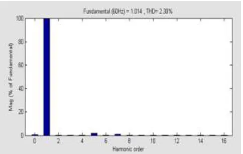
and 13th harmonic, double tuned band pass filter is connected across the 12 pulse voltage source converter output. Fig 5.9 shows SIMULINK diagram of 12 pulse voltage source converters STATCOM with 3Ø harmonic filter connected to the power system. The output load voltage mitigated by 12-pulse voltage-source converter STATCOM with 3Ø harmonic filter and its harmonic spectrum is shown in figures 5.10 and 5.11 respectively. In this respect, the voltage flicker is completely removed from the output load voltage and a sinusoidal waveform is obtained. It can be observed from the harmonic spectrum that THD is 2.30%.
Compensated output load voltage by 6-pulse voltage source converter STATCOM
Harmonic spectrum of the compensated output load voltage by 6-pulse
voltage-source converter STATCOM.
7 Output load voltage mitigated by 12-pulse voltage source converter STATCOM
Harmonic spectrum of the output load voltage mitigated by 12-pulse voltage-
source converter STATCOM.
Output load voltage mitigated by 12-pulse voltage source converter STATCOM
Harmonic spectrum of the output load voltage mitigated by 12-pulse voltage-source converter STATCOM
equipped with a harmonic filter.
Results analysis
:
Voltage flicker mitigation using 6 pulse voltage source converter STATCOM, 12 pulse voltage source converter STATCOM, and 12 pulse VSC STATCOM with 3Ø harmonic filter are simulated. The output load voltage without STATCOM and with STATCOM is obtained and compared. The results obtained are as follows:I. Without STATCOM:
The output load voltage is 1.3 Pu (maximum value).The voltage flicker existing in the output load voltage (exerted to the system) is 0.3 Pu (30%).
II. With STATCOM:
TABLE 5.1 Comparison of voltage flicker
mitigation and THD value of STATCOM compensators.
Compens
ator
Compensa
ted output
load
voltage
(maximum
Voltage
Flicker
THD
value)
6 pulse
VSC
STATCO
M
1.15 pu
Existing is
0.15 pu
(15%)
(or)
Mitigated by
50%
8.95
%
12 pulse
VSC
STATCO
M
1.0 pu Completely
mitigated
4.47
%
12 pulse
VSC
STATCO
M with
3Ø
harmonic
filter
1.0 pu Completely
mitigated
2.30
%
on voltage-source converters for voltage flicker mitigation has been investigated and simulation results emphasized its significant effect. A 6-pulse STATCOM is decreasing the voltage flicker by 50%. However, there is injection of the harmonic from 6-pulse STATCOM into the system which can be improved with the increase of the voltage source converters of STATCOM using a 12-pulse STATCOM equipped with a harmonic filter. The obtained results clearly demonstrate that 12-pulse STATCOM equipped with a harmonic filter can reduce the voltage flicker completely and the output is obtained with minimum THD Value.
REFERENCES:
[1] J. Sun, D. Czarkowski, Z. Zabar, “Voltage Flicker Mitigation Using PWM-Based Distribution STATCOM”, IEEE Power Engineering Society Summer Meeting, Vol.1, (21-25 July 2002), pp. 616-621.[2] N. G. Hingorani, L.Gyugyi, "Understanding FACTS", IEEE Press.
[3] Rozmyslaw , Miensik, Ryszard.pawelk , “Application of STATCOM controllers for powr quality improvement-Modelling and simulation.” IEEE Trans. (2002),0-7803-7671102...
[4] L. Tang, S. Kolluri, M.F. McGranaghan, "Voltage Flicker Prediction for Two Simultaneously Operated AC Arc Furnaces" IEEE Trans. on Power Delivery; Vol.12, No.2, (1997), pp. 985-991.
[5] M. Zouiti, S. Saadate, X. Lombard, C. Poumarede, C. Levillain, “Electronic Based Equipment for Flicker Mitigation”, Proceedings of International Conference on Harmonics And Quality of Power, Vol.2, (1998), pp. 1182-1187.
[6] T. Larsson, C. Poumarede, “STATCOM, an efficient means for flicker mitigation” IEEE Power Engineering Society Winter
Meeting, Vol.2, (Jan-4Feb 1999), pp. 1208-1213.
[7] C. S. Chen, H. J. Chuang, C. T. Hsu, S. M. Tscng, “Stochastic Voltage Flicker Analysis and Its Mitigation for Steel Industrial Power Systems”, IEEE Power Tech Proceedings, Vol.1, (10-13 Sept. 2001).
[8] Z. Zhang, N. R. Fahmi, W. T. Norris, “Flicker Analysis and Methods for Electric Arc Furnace Flicker (EAF) Mitigation (A Survey)”, IEEE Power Tech Proceedings, Vol.1, (10-13 Sept. 2001).
[9] J. R. Clouston, J. H. Gurney, “Field Demonstration of a Distribution Static Compensator Used to Mitigate Voltage Flicker”,IEEE Power Engineering Society Winter Meeting, Vol.2, (31 Jan-4 Feb 1999), pp. 1138- 1141.
[10] A. Elnady, W. El-khattam, M. A. Salama, “Mitigation of AC Arc Furnace Voltage Flicker Using the Unified Power Quality Conditioner”, IEEE Power Engineering Society Winter Meeting, Vol.2, (27-31 Jan. 2002), pp. 735-739.
[11] S. Suzuki, Y. Hara, E. Masada, M. Miyatake, K. Shutoh, “Application of Unified Flow Controller for Power Quality Control at Demand Side”, The Third International Power Electronics and Motion Control Conference Proceedings (PIEMC 2000), Vol.3 (15- 8Aug 2000), pp. 1031-1036.
[12] Y. Hara, E. Masada, M. Miyatake, K. Shutoh, “Application of Unified Flow Controller for Improvement of Power Quality” IEEE Power Engineering Society Winter Meeting, Vol.4, (23-27 Jan. 2000), pp. 2600-2606.
[14] B. P. Roberts, “Power Quality Solution Alternatives for Low and Medium Voltage Continuous Process Loads”, IEEE Rural Electric Power Conference, (5-7 May 2002), pp.C4-C4_7.
[15] G. C. Montanari, M. Loggini, L. Pitti, E. Tironi, D. Zaninelli, “The effects of series inductors for flicker reduction in electric power systems supplying arc furnaces”, IEEE Industry Applications Society Annual Meeting, Vol.2, (2-8 Oct. 1993), pp.1496-1503.
[16] M. W. Marshall, “Using Series Capacitors to Mitigate Voltage Flicker Problems” IEEE Rural Electric Power Conference, (20-22 April 1997), pp. B3-1-5. [17] John D. Kueck and Brendan J. Kirby, Philip N. Overholt. Lawrence C. Markel “Measurement practices for reliability and power quality” Oak Ridge National Laboratory Oak Ridge, Tennessee 37831-6285.2004JUN.
[18] L. Gyugi, A. A. Otto, “Static Shunt Compensation for Voltage Flicker Reduction and Power Factor Correction”, American Power Conference (1976), pp. 1272-1286. [19] A. de Almeida, L. Moreira. J. Delgado. “ Power Quality Problems and New Solutions” ISR – Department of Electrical and Computer Engineering University of Coimbra, Pólo II 3030-290 Coimbra (Portugal), 2001
[20] Fran~oisD . Martzloff,”Consumer power quality problems” National Rural Electric Cooperative Association Cooperative Research Network,2004.
[21] R. Mienski, R. Pawelek, I. Wasiak “Shunt Compensation for Power Quality Improvement using a STATCOM
controller:Modelling and simulation”, IEE Proc.-Gener. Transm. Distrib., No.2, Vol.151, (2004), pp. 274-280.
[22] David Chapman,“Harmonics Causes and Effects” Copper Development