Transactions of the 17th International Conference on Structural Mechanics in Reactor Technology (SMiRT 17)
Prague, Czech Republic, August 17 –22, 2003
Paper # F02-1
The B2 Stress Index as a Function of Internal Pressure, Bend Angle, Loading
Type and Material
Vernon C. Matzen 1) and Xi Yuan 2)
1) North Carolina State University, Raleigh, North Carolina, USA 2) Enginious Software, Raleigh, North Carolina, USA
ABSTRACT
The current ASME Boiler and Pressure Vessel Code equation for the B2 stress index, which is used in the design
equation for primary stresses in piping components, is widely considered to be overly conservative. In recent years, various researchers have investigated the behavior of piping components, primarily elbows, to determine the effect of parameters such as internal pressure, bend angle, location of adjacent flanges, loading type, etc. on the inelastic response of elbows. This paper contains a detailed evaluation of the effects of elbow size and schedule, loading type, internal pressure and material type on the collapse moments of straight pipes and elbows using nonlinear finite element analysis, and then uses these data to construct B2 stress indices for the various combinations of parameters. Using these
results, various equations for the stress index as a function of the pipe bend characteristic parameter, the bend angle, internal pressure and material type are investigated and an optimal form of one of the equations is recommended for use.
KEY WORDS: B2 stress index, collapse moments, inelastic behavior, nonlinear finite element analysis, carbon steel,
stainless steel, internal pressure, elbow bend angle, curvature definition, piping elbow components, piping design, nuclear power plants
INTRODUCTION
The B2 stress index is used in Equation (9) of the ASME Boiler and Pressure Vessel Code [1] for Class I piping to
control gross plastic deformation. For elbows, the Code gives the following equation for this index:
0 . 1 h
30 . 1
B2 = 23 ≥ (1)
where h is the characteristic pipe bend parameter (See the NOMENCLATURE section for more information.) This equation is independent of variables such as internal pressure, bend angle, temperature, material type, loading type, proximity to flanges or other components, although elbow behavior is known to be dependent on some or all of these variables. In 1991, Touboul and Acker [2] presented an equation, based on one given earlier by Dodge and Moore [3], for the stress index in which internal pressure and bend angle were also parameters. Their equation took the following form (after converting it to the notation used in this paper):
1
y 4
. 0
3 2
2 1 0.htS7
h 6 . 1 B
−
+ π α
= Prm (2)
In 2002, Matzen and Tan [4] described a new procedure for calculating the B2 stress index. Their equation took the
form:
elbow pipe straight
CL CL
2 M
M
B = (3)
where the collapse moments were obtained using nonlinear finite element analysis and were based on the twice-elastic slope method. The straight pipe must have the same geometric and material properties as the component. They considered only 90o, long radius, butt-welding, stainless steel 304L elbows at room temperature and quasi-static
service application or where a particular component response is needed; whereas the second might be used when design code equations are being investigated.
In this paper, we describe a study in which the Matzen and Tan approach is extended to include the effects of various other parameters on elbow behavior. Specifically, we consider the following:
• characteristic pipe bend parameter, h (5 values from h=0.072 (8” schedule 5) to h=0.997 (2” schedule 160))
• internal pressure (p=0, 0.618 and 1, where p is the ratio of internal pressure to the design pressure)
• bend angle (30, 90 and 150°)
• material type (one carbon steel and two stainless steels, one low strength and one high strength)
• loading type (in-plane closing and out-of-plane bending - results from in-plane opening mode and out-of-plane torsion showed that they rarely, if ever, governed.)
Using FEA results (with nominal geometric dimensions), we appraise the validity of Eqs. (1) and (2) and then investigate two other equations – both modifications of the Touboul and Acker equation.
B2 VALUES FROM FEA
Curvature definition
The FEA procedure used by Matzen and Tan in Eq. (3) requires that the moment-curvature graphs be obtained for both the component and the straight pipe. For the elbow component, the straight pipe segments welded to each end, which are included to remove end effects, should not be included in the curvature calculation. For in-plane loading, either opening or closing, this calculation is trivial if elbow elements are used. If shell elements are used (which was our case), then the situation is somewhat more complicated since plane sections may not remain plane. Our solution to this problem was to compute, at each end of the elbow, the vector from a node at the extrados to one at the intrados. At zero load and pressure, the angle between these two vectors, for a 90o elbow,
would be 90o. When the elbow deforms, then the angle between the two
vectors does also, and the difference between this angle and the starting angle can be easily calculated. We then define the curvature of an elbow as the change in this angle divided by the centerline length of the elbow.
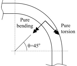
Fig. 1. Out-of-Plane Loading Modes Pure torsion Pure
bending
θ=45o We applied this same definition to out-of-plane behavior. There are two
modes of out-of-plane bending – one pure bending and the other pure torsion, both as defined at the mid-point of the elbow bend angle (although the moments are actually applied at the end of the straight portion of the pipe.) Figure 1 demonstrates these moments. In this case, the vector used in the curvature calculation runs from flank to flank rather than extrados to intrados. In the case of pure bending, we projected these vectors onto a plane that was perpendicular to the pure bending double-headed arrow shown in Fig. 1. The angle change between the vectors at each end of the component was used in the curvature definition. The application to pure torsion was similar.
Table 1 Elbow Sizes and Schedules Size Schedule h
8 5 0.0721
6 10 0.1145
6 40 0.2504
4 80 0.4667
2 160 0.9968
FEA results
In our FEA analyses, we investigated the five sizes and schedules of elbows shown in Table 1, using nominal geometric data for all dimensions. The internal pressures we considered were relative to the design pressure,
yt 2 D
t S 2 P
o m
a = − , where Sm was taken to be min(31Sy,32Su). The pressures
were 0, 0.618Pa, and Pa. The three materials are defined in Table 2. The total
number of B2 values computed then, was 5 values of h * 3 pressures * 3
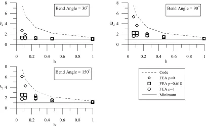
bend angles * 3 materials * 2 loading conditions for a total of 270. For the two loading conditions, the results were quite similar, but we always used the maximum of the two B2 values. For zero pressure, in-plane closing
always controlled, i.e. it had the highest value of B2. For the other two
pressures, the results were mixed, but the differences between the two values (for given h, bend angle, etc) were small (< 5%). A set of typical results is shown in Fig. 2.
Table 2 Material Properties (ksi) Designation Sy Su Sm
Carbon Steel SA-36
36 58 19.3
Stainless Steel – 25 70 16.7
Stainless Steel – 50 100 33.3 High Strength
304L
0 0.2 0.4 0.6 0.8 1 h
0 2 4 6 8
B2
Bend Angle = 30o
0 0.2 0.4 0.6 0.8 1
h 0
2 4 6 8
B2
Bend Angle = 90o
0 0.2 0.4 0.6 0.8 1
h 0
2 4 6 8
B2
Code FEA p=0 FEA p=0.618 FEA p=1 Minimum
Bend Angle = 150o
Fig. 2. FEA results for SS 304L, including the Code equation and the minimum value.
DEVELOPMENT OF B2 EQUATION
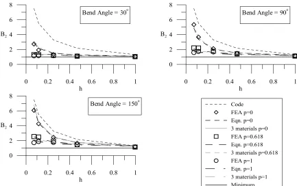
As described above, we first investigated the equation given by Touboul and Acker in Ref. [2]. These results for SS 304L are given in Fig. 3. We observe that the values can be less than one, which is the minimum value, and the correlation is not particularly good. We also considered two modifications of their equation. The first was an equation with exactly the same form as Eq. (2), but with the constants left as variables. We then optimized the equation by minimizing the squared difference between this equation and the FEA data. The constants 1.60, 0.70, 2/3 and 0.40 became 1.33, 0.21, 0.59 and 0.38, respectively. These results are shown in Fig. 4 - again, some values are less than one, but the correlation is much improved. To overcome the problem of having values that are less than one, we modified the equation by adding the constant one to it. The resulting equation, with the four open variables designated c1 and c2
for the coefficients, and e1 and e2 for the exponents, is as follows:
1
y e
e 1
2 1 htS
h c 1
B 2
1
−
+ π α +
= c2Prm (4)
Again computing a squared error and minimizing it, we obtained the following values for the four constants: c1=0.37,
c2=0.45, e1=1.07 and e2=0.66. These results for Eqn. (4), referred to as the NCSU equation, are shown in Fig. 5.
All of the above results are for SS 304L. Results for the other two materials (carbon steel and a high strength stainless steel, neither of which is shown) were similar, but the values of the constants were somewhat different. To obtain one “best fit” equation for all three materials, we computed a single squared error by using FEA results and the appropriate value for Sy for each material, but with the same set of constants in Eqn. (4). These results are shown in
Fig. 5. They are the light grey lines, and it is a bit difficult to see them since they are quite close to the curves for 304L. Table 3 summarizes the results. The last line of the table is the squared error for each equation.
Table 3. Coefficients and Exponents for B2 Equations
Touboul and Acker, Ref. [2] Optimized Touboul and Acker NCSU Equation
A B C A B C A B C D
c1 1.60 1.60 1.60 1.33 1.29 1.31 0.37 0.35 0.37 0.36
c2 0.70 0.70 0.70 0.21 0.34 0.28 0.45 0.88 0.55 0.60
e1 0.67 0.67 0.67 0.59 0.65 0.62 1.07 1.14 1.10 1.10
e2 0.40 0.40 0.40 0.38 0.37 0.39 0.66 0.59 0.64 0.63
Sum Sq Err 22.37 13.95 19.53 2.14 2.44 2.19 1.20 1.10 1.13 5.31
0 0.2 0.4 0.6 0.8 1 h
0 2 4 6 8
B2
Bend Angle = 30o
0 0.2 0.4 0.6 0.8 1
h 0
2 4 6 8
B2
Bend Angle = 90o
0 0.2 0.4 0.6 0.8 1
h 0
2 4 6 8
B2
Code FEA p=0 Eqn. p=0 FEA p=0.618 Eqn. p=0.618 FEA p=1 Eqn. p=1 Minimum Bend Angle = 150o
Fig. 3. Touboul and Acker [2] equation for SS 304L
0 0.2 0.4 0.6 0.8 1
h 0
2 4 6 8
B2
Bend Angle = 30o
0 0.2 0.4 0.6 0.8 1
h 0
2 4 6 8
B2
Bend Angle = 90o
0 0.2 0.4 0.6 0.8 1
h 0
2 4 6 8
B2
Code FEA p=0 Eqn. p=0 FEA p=0.618 Eqn. p=0.618 FEA p=1 Eqn. p=1 Minimum
Bend Angle = 150o
0 0.2 0.4 0.6 0.8 1 h
0 2 4 6 8
B2
Bend Angle = 30o
0 0.2 0.4 0.6 0.8 1
h 0
2 4 6 8
B2
Bend Angle = 90o
0 0.2 0.4 0.6 0.8 1
h 0
2 4 6 8
B2
Code FEA p=0 Eqn. p=0 3 materials p=0 FEA p=0.618 Eqn. p=0.618 3 materials p=0.618 FEA p=1
Eqn. p=1 3 materials p=1 Minimum Bend Angle = 150o
Fig. 5. NCSU equation for SS 304L and the combined set of materials (labeled 3 materials.)
SUMMARY AND CONCLUSION
We used nonlinear FEA to compute B2 stress indices for 270 combinations of elbow size and schedule, material
type, internal pressure, and bend angle using Eq. (3). Only 90 of those results – the ones for SS 304L - are shown here, but the results for high strength stainless steel and carbon steel SA-36 were similar. We then investigated the ability of three different equations plus the current Code equation to simulate these FEA results. Both the Optimized Touboul and Acker equation and the NCSU equation match the FEA data quite well, but the NCSU equation has the advantage of always remaining above the minimum value of one. Thus, we conclude that the most appropriate equation for obtaining the B2 stress index for any combination of size and schedule, bend angle, internal pressure, material and loading type is
the NCSU equation with the constants obtained from the combined sets of material data. This equation is given below.
1
y 63
. 0
10 . 1 2
htS 1 h
36 . 0 1 B
−
+ π α +
= 0.60Prm (5)
NOMENCLATURE
B2 = primary stress index for bending c1, c2 = coefficients in an equation for B2
Do = outside diameter of pipe e1, e2 = exponents in an equation for B2
h = characteristic bend parameter, tR/rm2
elbow CL
M = Twice-elastic slope collapse moment for an elbow
p a
a = = Twice-elastic slope collapse moment for a straight pipe
p = normalized pressure, P/Pa P = internal pressure
Pa = allowable working pressure R = nominal bend radius of elbow rm = mean pipe radius, (Do-t)/2 Sm = allowable design stress intensity
Sy = yield stress Su = ultimate stress
ACKNOWLEDGEMENT:
The authors would like to acknowledge the support of the Center for Nuclear Power Plant Structures, Equipment and Piping at North Carolina State University, the PVRC Subcommittee on Flexibility Models and Stress Intensification Factors (Grant 98-PNV-6) and the North Carolina Supercomputing Center.
REFERENCE:
1 ASME. Boiler and Pressure Vessel Code, Section III, Division 1, Subsection NB-3600 Piping Design, The American
Society of Mechanical Engineers, 2001.
2 Touboul, F. & Acker, D., “Excessive Deformation and Failure of Straight parts and Elbows,” Proceedings of SMiRT
11, Paper E02/2, pp. 19-24, Tokyo, Japan, August 1991.
3 Dodge, W. G. and Moore, S. E., “Stress Indices and Flexibility Factors for Moment Loadings on Elbows and Curved
Pipe,” WRC Bulletin 179, December 1972.
4 Matzen, V. C. and Tan, Y., “The History of the B
2 Stress Index.,” ASME Journal of Pressure Vessel Technology,
Vol. 124 , No. 2, 2002, pp 168-176.
![Fig. 3. Touboul and Acker [2] equation for SS 304L](https://thumb-us.123doks.com/thumbv2/123dok_us/1750153.1224396/4.595.94.502.72.317/fig-touboul-acker-equation-ss-l.webp)