Code Regeneration Scheme for Data Integrity
and Identity Based Data Uploading for
Hospital Data’s
Abhinav N D1, Basavesha D2
PG Student, Dept. of CSE., SIET, Visvesvaraya Technological University, Belagavi, India1
Assistant Professor, Dept. of CSE., SIET, Visvesvaraya Technological University, Belagavi, India2
ABSTRACT: From the past decade, cloud computing has been emerging exponentially. Many service providers provide their services and in some cases just limit their service to provide storage. Hospital is one among such a client who uses the services for storage of the hospital’s data. Now a days, the security for the data need to be addressed at the earliest. Similarly, security for the patient’s data in the hospital is also an immediate attention driving issue. Hence, in our paper we present an Identity Based Data Uploading and Code Regeneration based data integrity and availability methods which provides security for the patients data in hospitals.
KEYWORDS: Code regeneration ; mapping unit ; Proxy Key ; Combining unit ; Private Key Distribution And Generation Centre (PKDGC) ; master secret key ; Data uploader ; Data generator.
I. INTRODUCTION
Due to the drastic increase in the technology of cloud computing and its communication services, peta byte and zeta byte of data are been accumulated and stored every day. Hospital is one such organisation which uses the cloud services, because the number of patients are increasing day by day. Massive data’s are been generated and need to provide storage space for all the patients data. Along with this, computational resources for providing the security of the data, processing the data’s etc also need to be addressed.
From the past decades, the number of patients been admitted to hospitals and all those exponentially growing patients data’s need to be provided with security, confidentiality, availability, storage space and computational resources so and so forth. Compromise with any of these can never be thought of and every ascept places their own importance in the real world[10].
For the same may organisations, specially hospitals are been owning a group of servers which we call as cloud , that corresponds to their own organisation. [12]All the resources and other ascepts are been dealt with respective organisations. Many organisations, now a days are using cloud of their own and services provided by those clouds will be for that particular organisation and the resources will be dedicated for that organisation.
With respect to the security concerns of the hospital organisation, in our proposed system model, we propose a identity based data uploading via proxies and code regeneration for providing the data integrity. Many existing systems provide security and have addressed the problem, but our system provides an efficient and an effective way than any other systems proposed till date.
II. RELATED WORK
prevent consent attacks. As the re encryption key is generated using the master key of the PKG (a fully trusted private key generator), the proxy and the delegate can-not advance delegate the decryption spot on to others without the help of the PKG. Moreover, it is a solution undesirable in view of the fact that PKG is such a scheme that can decrypt both actual and ciphertexts.
Additionally, PKG can shift any re encryption key for other clients, that is, the assignable hitch is still not been solved. Later, Hayashi et al. [14] introduce a relaxing notions for non transferability and anticipated two tangible constructions. Unfortunately, Isshiki et al. [17] pointed out that Hayashi et al.’s scheme is vulnerable to the forge ability attack of re encryption key. Likewise, the security assumptions deployed during proving the concepts can be solved economically. Presently, Guo et al. [13] anticipated an well-organized PRE scheme with un forgeable re-encryption keys.
As Gentry and Silverberg [16] projected the first notion of hierarchical encryption scheme, many hierarchical CP-ABE schemes have been proposed. For example, Wang et al. [17] proposed a hierarchical ABE scheme by combining the hierarchical IBE [2] and CP-ABE. Wan et al. [18] proposed hierarchical ABE scheme. Later, Zou [2] gave a hierarchical ABE scheme, while the length of secret key is linear with the order of the attribute set. A cipher text policy hierarchical ABE scheme with short ciphertext is also studied in [3]. In these schemes, the parent authorization domain governs its child authorization domains and a top-level authorization domain creates secret key of the next-level domain.
The main work of key establishment is concentrated on multiple permission domains and the encumber of key authority centre is lightened. At at hand, there exists three types of way in structures ; AND gate, access tree, and linear secret sharing scheme (LSSS) used in existing CP-ABE schemes.
Cheung and Newport [12] first used AND gate access structure to achieve CP-ABE scheme. Later, some improved schemes [15], [16], [17] are proposed. In the meantime, there are CP-ABE scheme base on access tree [11], [14], that carry AND, OR, and threshold, and based on LSSS [16], [18], [17], where [11] and [12] are the typical schemes of access tree and LSSS.
III.PROPOSED SYSTEM
We propose a system model, that uses Identity ID of the components as one of the parameter regarding security. The various components of the model are : Doctor, Data generator, Data uploader, Patient, Proxies, PKDGC, Mapping and combining units.
The initial phases employed before the processing of the data are as follows:
1. Setup phase :- A security parameter “sp” is as input to algorithm , which outputs the master secret key which will provide confidentiality. This is done by PKDGC.
2. Extract :- When the identity, ID , are given as input, PKDGC will output a private key PKID which corresponds to the identity ID.
3. Proxy-Key Generation :- This component will generate a warrant and signature pair and send it to the proxy. The proxy correspondingly will generate proxy key using its own private key.
The above phases are been performed for the components : Proxies ; Doctor ; Data uploader . The reason is that they are the entities that take part in data uploading and downloading.
Initially, when all the basic initial phases are done, the actual process starts. The various stages in which the architecture works are given below. The roles of all the components are also been visited.
(1) Firstly , the patients fixes an appointment with the doctor. After concerting the doctor, he may prescribe some of the
tests or examinations to the patients.
(2) Patients, then move towards the Data generator unit. This is the person who will perform the test as been prescribed by the doctor. The examination prescribed may be :
[A] X-Ray.
[B] Scanning (Different types). [C] Blood Test and so on and so forth.
(3) After the data been generated by the generator, he will update the patients record. If the check up is done for the first time, it will be registered or stored for the first time, else, updating of the register or existing data that is stored already in the database.
(4) The Data uploader, requests for the data from the Data generator , he will in turn provide the data to the Data uploader.
(5) The Data uploader before uploading the clients data i.e. the patients data onto the cloud , he generates the security parameters. Initially, the Data uploader sends the ID of itself to the private key distribution and generation centre. This key generation centre assign’s the private key PKUL corresponding to the IDUL of the Data uploader.
(6) Then, the uploader signs the key corresponding to the ID of the Data uploader and signs the key and passes its data to the proxy. The signature that is been sent by the Data uploader will be authenticated by the proxy. The proxy will also had been undergone private key generation process as the Data uploader with the identity of being IDP2 for
proxy-2 with its private key PKP2.
(7) The proxy in turn will generate a proxy key for the corresponding data and the identity. The proxy will now send the data to the mapping unit.
(8) Mapping unit is an component that divides the blocks of the Data generated by the generator components and stores on the different servers for the purpose of the security.
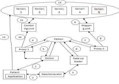
Fig 1:System Architecture
In the above figure, number from 1 to 13 are been mentioned. Now let us see the functioning of all the above components.
(1) Patient goes to the doctor and doctor prescribes for some tests.
(2) Data Generator checkups the patient and updates the patient’s database.
(3) Data up loader requests for the data and the data generator provides the data for uploading. (4) Proxy-1 identity is IDP1 and secret key is PKP1.
(5) Doctor identity is IDD and its secret key is PKD.
(7) Proxy-2 identity is IDP2 and secret key is PKP2.
(8) Proxy-2 send data to the mapping unit.
(9) Mapping unit divides data into chunks and stores on to the server. (10) Proxy-2 requests combining unit for data.
(11) Combining unit fetches all the data from server.
(12) Patient directly access the data from server via application.
(13) This is cloud with many servers and code regeneration is been done if required.
The <data, id1,id2,Tag> is the values that are been generated alone with the data. id1 identifies the data corresponding to the patient. id2 is used by the patients for accessing there data directly from the server. Tag is the value that will be stored with each block of data that will be distributed and stored across the cloud.
data, id1,id2,Tag , are the four values that are been generated.
<data, tag> pair is sent to the server for storage of the data.
id1 is used by the doctors for perceiving the corresponding patients data. Doctor will access the data when the patient is in front of doctor for treatment.
id2 is used by the patients for perceiving their data. They can access their data from home or from any place they are in until he is cured or he is been detached from the hospital.
An application needs to be built in order to provide patients data directly to on self.
Code regeneration is used only for regenerating the data during the data loss or during the corruption of the data that is been stored on the server and so on.
The data can be of any size say “n” and “tag” is the data that identifies the full block of size “n” . This is been divided into number of small chunks of data, may be n/24 or n/16. Etc will all be assigned Tag and stored by distributing them across the cloud network.
This is done in order to protect from complete loss of the data during the server failure or any other such type of the scenario.
Similarly, the doctor performs all the setup phases and via proxy-1,beering the identity IDP1 and its private key
being PKP1 ,same as the Data uploader. Working doctor fetches the data from combining unit. This unit, with the help
of the id provided by the doctor and the tag for the data that is been stored in the server, combine unit will fetch all the data blocks stored across the cloud, combine it to a single unit and makes the data available to the doctor.
(9) Private key distribution and generation centre will provide its facilities for proxies , doctors and the Data uploaders components to provide security for the Data uploader components to provide security for the data during uploading to the remote cloud. The Tag and the Identity is unique for all the patients data’s.
(10) The patients, in turn, can access his data from the application that is been available and is using id2 (The Tag and the Identity is unique for all the patients data’s) , will be able to fetch his data from the cloud. The patients will be able to access his data until he is been detached from the hospital or not been visited anymore. But the doctors can access to the data any how and when every needed in future.
(11) Since, our patients data are been stored on different servers, if any of the servers fails, or if data been corrupted , code regeneration algorithm will regenerate the lost data and will provide the original or the actual data to the patients and the doctor. We have employed this to overcome the drawback of redundancy delays and confusions and also for its space consumption.
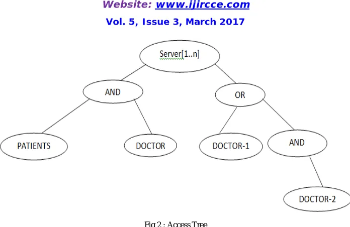
Below tree gives the information that , the data stored in the server can be accessed by both the patients and the doctor. At times, doctor-1 or doctor-2 or both the doctor-1 and doctor-2 can access the data.
Fig 2 : Access Tree
The root nodes is server which is the centre where all the patients data are been stored. From the same server only the doctors or the patients or the data generator can access the data. AND shows that the nodes below them are called as child nodes . Staring from the leaf node , we can say that both the patient and the doctor can share the data.
Now next coming to the left subtree, we can see that OR is been used. This Says that only one person can be able to see the or fetch the data data from the server. Next level is the right subtree of the OR node indicating that the AND is been used and both the doctors in some cases, will be able to access the date.
There can be any number of servers and fetching of the data means complete block of the data is been fetched from the servers directly.
IV.ADVANTAGES OF PROPOSED ALGORITHM
(1) Both the patients and the doctor can at the same time access the data from the server.
(2) Patients can access the data any number of times until he is been completely detached or been cured completely. (3) Secure data uploading via proxies by generating private and secret keys.
(4) Patients and doctors , both can just view the data , but not modify or alter the data. (5) Code regeneration provides data integrity and availability.
(6) Security can also be provided by the application that is been is been used by the patients.
V .CONCLUSION
Our proposed system provides security for the data during the data uploading and also during the fetching of the data from the cloud. At the times of server failure, code regeneration algorithm, protects the data by regenerating the same actual data. The original data is been obtained back.
Since, we have many entities like identities, secret key, private key etc has been generated for all those components who wants to access and store the data, except for the patients, we are providing the security at the very best level and chance of misuse is been reduced in our proposed system.
VI .FUTURE WORK
REFERENCES
1. C.-K. Chu, W.-T. Zhu, J. Han, J.-K. Liu, J. Xu, and J. Zhou, “Security concerns in popular cloud storage services,” IEEE Pervasive Compute., vol. 12, no. 4, pp. 50–57, Oct./Dec. 2013.
2. T. Jiang, X. Chen, J. Li, D. S. Wong, J. Ma, and J. Liu, “TIMER: Secure and reliable cloud storage against data re-outsourcing,” in Proc. 10th Int. Conf. Inf. Secuer Pract. Experiment., vol. 8434. May 2014, pp. 346–358.
3. K. Liang, J. K. Liu, D. S. Wong, and W. Susilo, “An efficient cloud based revocable identity-based proxy re-encryption scheme for public clouds data sharing,” in Proc. 19th Eur. Symp. Res. Comput. Secur., vol. 8712. Sep. 2014, pp. 257–272.
4. T. H. Yuen, Y. Zhang, S. M. Yiu, and J. K. Liu, “Identity-based encryption with post-challenge auxiliary inputs for secure cloud applications and sensor networks,” in Proc. 19th Eur. Symp. Res. Comput. Secur., vol. 8712. Sep. 2014, pp. 130–147.
5. K. Liang et al., “A DFA-based functional proxy re-encryption scheme for secure public cloud data sharing,” IEEE Trans. Inf. Forensics Security, vol. 9, no. 10, pp. 1667–1680, Oct. 2014.
6. T. H. Yuen, J. K. Liu, M. H. Au, X. Huang, W. Susilo, and J. Zhou, “k-times attribute-based anonymous access control for cloud computing,” IEEE Trans. Comput., vol. 64, no. 9, pp. 2595–2608, Sep. 2015.
7. J. K. Liu, M. H. Au, X. Huang, R. Lu, and J. Li, “Fine-grained two factor access control for Web-based cloud computing services,” IEEE Trans. Inf. Forensics Security, vol. 11, no. 3, pp. 484–497, Mar. 2016.
8. W. Zhu, J. Yu, T. Wang, P. Zhang, and W. Xie, “Efficient attribute-based encryption from R-LWE,” Chin. J. Electron., vol. 23, no. 4, = pp. 778–782, Oct. 2014.
9. G. Ateniese, R. Di Pietro, L. V. Mancini, and G. Tsudik, “Scalable and efficient provable data possession,” in Proc. Secure Comm, 2008, Art. ID
10. C. C. Erway, A. Küpçü, C. Papamanthou, and R. Tamassia, “Dynamic provable data possession,” in Proc. CCS, 2009, pp. 213–222. 11. E. Esiner, A. Küpçü, and Ö. Özkasap, “Analysis and optimization on FlexDPDP: A practical solution for dynamic provable data
possession,” Intelligent Cloud Computing (Lecture Notes in Computer Science), vol. 8993. Berlin, Germany: Springer-Verlag, 2014, pp. 65–83.
12. E. Zhou and Z. Li, “An improved remote data possession checking protocol in cloud storage,” in Algorithms and Architectures for Parallel Processing (Lecture Notes in Computer Science), vol. 8631. Berlin, Germany: Springer-Verlag, 2014, pp. 611–617.
13. H. Wang, “Proxy provable data possession in public clouds,” IEEE Trans. Services Comput., vol. 6, no. 4, pp. 551–559, Oct./Dec. 2013. 14. H. Wang, “Identity-based distributed provable data possession in multicloud storage,” IEEE Trans. Services Comput., vol. 8, no. 2, pp. 328–
340, Mar./Apr. 2015.
15. H. Wang, Q. Wu, B. Qin, and J. Domingo-Ferrer, “FRR: Fair remote retrieval of outsourced private medical records in electronic health networks,” J. Biomed. Inform., vol. 50, pp. 226–233, Aug. 2014.