University of Windsor University of Windsor
Scholarship at UWindsor
Scholarship at UWindsor
Electronic Theses and Dissertations Theses, Dissertations, and Major Papers
2016
In-plane dynamic behaviour of conventional and hybrid cable
In-plane dynamic behaviour of conventional and hybrid cable
network systems on cable-stayed bridges
network systems on cable-stayed bridges
Javaid Ahmad University of Windsor
Follow this and additional works at: https://scholar.uwindsor.ca/etd
Recommended Citation Recommended Citation
Ahmad, Javaid, "In-plane dynamic behaviour of conventional and hybrid cable network systems on cable-stayed bridges" (2016). Electronic Theses and Dissertations. 5795.
https://scholar.uwindsor.ca/etd/5795
This online database contains the full-text of PhD dissertations and Masters’ theses of University of Windsor students from 1954 forward. These documents are made available for personal study and research purposes only, in accordance with the Canadian Copyright Act and the Creative Commons license—CC BY-NC-ND (Attribution, Non-Commercial, No Derivative Works). Under this license, works must always be attributed to the copyright holder (original author), cannot be used for any commercial purposes, and may not be altered. Any other use would require the permission of the copyright holder. Students may inquire about withdrawing their dissertation and/or thesis from this database. For additional inquiries, please contact the repository administrator via email
In-plane dynamic behaviour of conventional and hybrid
cable network systems on cable-stayed bridges
By
Javaid Ahmad
A Dissertation
Submitted to the Faculty of Graduate Studies
through the Department of Civil and Environmental Engineering in Partial Fulfillment of the Requirements for
the Degree of Doctor of Philosophy at the University of Windsor
Windsor, Ontario, Canada
2016
In-plane dynamic behaviour of conventional and hybrid cable
network systems on cable-stayed bridges
by
Javaid Ahmad
APPROVED BY:
______________________________________________ L. Caracoglia, External Examiner
Department of Civil and Environmental Engineering, Northeastern University, Boston
___________________________________________ V. Stoilov, Outside Reader
Mechanical, Automotive & Materials Engineering
______________________________________________ S. Das, Department Reader
Civil and Environmental Engineering
______________________________________________ A. El Ragaby, Department Reader
Civil and Environmental Engineering
______________________________________________ S. Cheng, Advisor
Civil and Environmental Engineering
______________________________________________ F. Ghrib, Co-Advisor
Civil and Environmental Engineering
iii
DECLARATION OF CO-AUTHORSHIP/PREVIOUS
PUBLICATION
I.
Co-Authorship Declaration
I hereby declare that this dissertation incorporates material that is the result of joint
research undertaken with my Advisors, Dr. Shaohong Cheng and Dr. Faouzi Ghrib of the
University of Windsor. In all cases, the key ideas, the primary contributions, and data
analysis and interpretation were performed by the author of this dissertation. The
contributions of the co-authors were primarily focused on the provision of the study and
suggesting possible directions. Results related to this research are reported in Chapters 3
through 9, inclusive.
I am aware of the University of Windsor's Senate Policy on Authorship and I
certify that I have properly acknowledged the contributions of the other researchers to my
dissertation, and I have obtained written permission from my co-authors to include the
above materials in my dissertation.
I certify that, with the above qualification, this dissertation, and the research to
which it refers to, is the product of my own work.
II.
Declaration of Previous Publication
There are 11 original papers based on the contents of the dissertation that have been
previously published/submitted for publication in peer reviewed journals, as follows:
Dissertation Chapter
Publication Title Publication Status
Chapters 3 Analytical study on in-plane free vibration of a cable
network with straight alignment rigid cross-ties
iv
Chapter 3 An analytical approach to evaluate damping property
of orthogonal cable networks
Engineering
Structures: 2014, Vol. 75, 225–236.
Chapter 3 Impact of cross-tie properties on the modal behaviour
of cable networks on cable-stayed bridges
The Scientific World Journal: 2015, Vol. 215 doi:10:
1155/2015/989536. Chapter 3 Effect of cross-tie solution on the modal frequency
and modal damping of cable networks
Proc: 7th IABMAS, Shanghai, China, 2014, ID: 05714P
Chapter 3 Analytical study on in-plane modal properties of a
general cable network
Proc: 9th Int. Symp. on Cable Dynamics, Shanghai, China, 2011, pp.39–46.
Chapter 4 Impact of cross-tie design on the in-plane stiffness
and local mode formation of cable networks on
cable-stayed bridges
Journal of Sound and Vibration: 2016, Vol. 363, 141–155.
Chapter 5 Effect of the number of cross-tie lines on the in-plane
stiffness and modal behaviour classification of
orthogonal cable networks with multiple lines of
transverse flexible cross-ties
Journal of Engineering Mechanics, ASCE: 2016, Vol. 142(4), 04015106-13.
Chapter 6 Impact of key system parameters on the in-plane
dynamic response of a cable network
Journal of Structural Engineering, ASCE: 2014, Vol. 140, 104013079-10. Chapter 6 Effect of cross-link stiffness on the in-plane free
vibration behaviour of a two-cable network
Engineering
Structures: 2013, Vol. 52, 570–580.
Chapter 7 Analytical study on the in-plane dynamic behaviour
of hybrid cable networks and design optimization
Structural Control and Health Monitoring (Submitted) Chapter 7 Formulating analytical model of conventional and hybrid
cable system using a generalized approach
Journal of Sound and Vibration (Submitted)
I declare that, to the best of my knowledge, my dissertation does not infringe upon
anyone’s copyright nor violate any proprietary rights and that any ideas, techniques,
quotations, or any other material from the work of other people included in my
v
standard referencing practices. Furthermore, to the extent that I have included
copyrighted material that surpasses the bounds of fair dealing within the meaning of the
Canada Copyright Act, I certify that I have obtained a written permission from the
copyright owners to include such materials in my dissertation.
I declare that this is a true copy of my dissertation, including any final revisions,
as approved by my dissertation committee and the Graduate Studies office, and that this
dissertation has not been submitted for a higher degree to any other University or
vi
ABSTRACT
Stay cables on cable-stayed bridges are vulnerable to dynamic excitations due to their
long flexible feature and low intrinsic damping. Connecting a vulnerable cable with the
neighbouring ones through cross-ties to form a cable network is one of the commonly
used field solutions. The current dissertation is dedicated to explore the in-plane dynamic
behaviour of the conventional (cross-tie only) and hybrid (combined use of cross-ties and
external dampers) cable networks used for controlling undesirable bridge stay cable
vibrations. Their performances are evaluated based on the system in-plane stiffness,
damping and the severity of local mode formation.
A number of analytical models have been developed to analyze the in-plane
modal response of conventional cable networks by gradually extending the model of a
basic undamped two-cable network with a rigid cross-tie to include the cross-tie stiffness,
the damping property of main cables and cross-tie, and more number of main cables and
cross-tie lines into the formulation. A damping transfer phenomenon between cable
network elements having different damping properties was observed. Two criteria, the
degree of mode localization (DML) coefficient and the local mode cluster (LMC), were
proposed to quantify the severity of local mode formation. Based on the proposed
analytical models, key system parameters which dictate the dynamic behaviour of
conventional cable networks were identified. A parametric study was conducted to
explore their respective role in influencing the in-plane stiffness, the damping ratio and
the local mode formation of cable networks.
Analytical models of two-cable hybrid networks with different configurations
vii
“isoquant curve” was proposed to optimize the performance of a selected hybrid system
mode. A state-of-the-art generalized approach was developed to derive analytical models
of a more complex conventional or hybrid cable network from a relatively simple parent
system. Results indicated that the existing universal damping estimation curve for a
single isolated damped cable was no longer applicable once the cable became part of a
hybrid system. Thus, approximate relation equations were developed to predict the
optimum damper size and the maximum attainable fundamental modal damping ratio of a
basic two-cable hybrid system.
All the proposed analytical models were validated through independent numerical
simulations using the commercial finite element software Abaqus 6.10. Besides, an
experimental study was conducted for two-cable conventional and hybrid networks to not
only verify the validity of the corresponding analytical and numerical models, but also
evaluate the impact of different assumptions made in the formulation of these models on
the system modal response.
The outcomes yielded from this study are expected to add valuable knowledge to
comprehend the current understanding of the mechanics associated with the conventional
and hybrid cable networks. The developed tools will greatly contribute to the bridge
industry by assisting optimum design of conventional and hybrid cable networks,
especially in the preliminary design stage. Besides, it is worthy pointing out that the
current findings will also contribute to the knowledge of structural health monitoring,
assessment and management of bridges, and the development of more sustainable civil
viii
DEDICATION
I would like to dedicate my work to my mother and the memory of my father who
ix
ACKNOWLEDGEMENTS
I would like to express my deepest appreciation and gratitude to my research advisors,
Dr. Shaohong Cheng and Dr. Faouzi Ghrib, for their patient guidance, fruitful
discussions, and kind support during the course of this study. I believe such a technical
research would not have been possible without their kind supervision.
Also I would like to thank Dr. Vesselin Stoilov for his technical assistance to
solve some of the mathematical problems. The advice and comments made by Dr.
Sreekanta Das and Dr. Amr El Ragaby are also assets for me to complete this project.
I must thank Dr. Luca Caracoglia at the Northeastern University, Boston, USA for
taking the responsibility as the external reviewer of my dissertation.
I would like to thank laboratory technologist Mr. Lucian Pop for his help and
suggestions with the experimental setup, and computer systems administrator Mr. Mark
Gryn for his help for all the computer related issues. Lastly, I would also like to thank
my colleagues, Ali, Kashif, and Gnanasekaran for their incredible help and support.
Finally, I would like to thank my family, Riffat, Usama, Sara and Talha, for their
x
TABLE OF CONTENTS
DECLARATION OF CO-AUTHORSHIP/PREVIOUS PUBLICATION iii
ABSTRACT vi
DEDICATION viii
ACKNOWLEDGEMENTS ix
LIST OF FIGURES xiv
LIST OF TABLES xxiii
CHAPTER 1 Introduction 1
1.1 Background 1
1.2 Types of wind-induced cable vibrations 3
1.3 Countermeasures 6
1.4 Motivations 12
1.5 Objectives 14
CHAPTER 2 Literature Review 16
2.1 Free vibration of a single cable 16
2.2 Modal behaviour of cable networks 19
2.2.1 In-plane frequency 19
2.2.2 Modal damping 23
2.2.3 Energy Distribution 26
2.2.4 Local mode formation 27
2.2.5 Role of different system parameters 29
2.3 Hybrid system 31
2.4 Summary 33
CHAPTER 3 Analytical Study on Modal Behaviour of Cable Networks 35
3.1 Undamped Two-Cable Networks 35
3.1.1 System characteristic equation 36
3.1.2 Twin-cable network with a flexible cross-tie at arbitrary location 40 3.1.3 Symmetric two-cable network with a flexible cross-tie at mid-span 47 3.1.4 Asymmetric two-cable network with a flexible cross-tie at one-third span 50
xi
3.2.1 System characteristic equation 56
3.2.2 Application examples 62
3.2.2.1 Twin-cable rigid cross-tie network 63
3.2.2.2 Symmetric DMT two-cable rigid cross-tie network 70 3.2.2.3 Asymmetric DMT two-cable rigid cross-tie network 80 3.2.2.4 Twin-cable damped flexible cross-tie network 87 3.2.2.5 Symmetric DMT damped flexible cross-tie Cable Network 96 3.2.2.6 Asymmetric DMT damped flexible cross-tie Cable Network 102
3.3 Summary 108
CHAPTER 4 Modal Analysis of General Cable Network 110
4.1 Formulation of analytical model 110
4.2 Application to cable networks with real configurations 114
4.2.1 Five Cable Network 115
4.2.2 Cable Network on the Fred Hartman Bridge 118
4.3 Summary 124
CHAPTER 5 Formation of Local Modes 126
5.1 Mode localization in cable-stayed bridges 127
5.2 Degree of mode localization and system parameters 128
5.2.1 Degree of mode localization 135
5.2.2 Role of system parameters on degree of mode localization 136
5.2.2.1 Frequency ratio 138
5.2.2.2 Mass-tension ratio 145
5.2.2.3 Cross-tie stiffness 149
5.3 Local mode clusters 154
5.3.1 Cross-tie position effect 157
5.3.2 Cross-tie stiffness effect 167
5.3.3 Effect of number of cross-tie lines 174
5.4 Summary 176
CHAPTER 6 Effect of System Parameters on Modal Behaviour of Cable Networks 179
6.1 Length ratio 181
6.2 Frequency ratio 189
6.3 Mass-tension ratio 194
xii
6.5 Cross-tie stiffness 215
6.6 Number of cross-tie lines 221
6.7 Summary 225
CHAPTER 7 Hybrid System 227
7.1 Introduction 227
7.2 Formulation of the Analytical Model 234
7.3 Model validation 239
7.4 Generalized approach 246
a) A single taut cable attached with a transverse linear viscous damper 248 b) A single taut cable with a transverse linear viscous damper and a transverse linear
spring 249
c) A single taut cable with two transverse linear viscous dampers 250
d) A two-cable network with connection to ground 251
e) A two-cable network with transverse linear viscous dampers installed on both cables 255
7.5 Parametric Study 259
7.5.1 Cross-tie stiffness 261
7.5.2 Spacing between damper and cross-tie 266
7.6 Design Optimization 273
7.7 Damping estimation curves for hybrid systems 280
7.7.1 Effect of cross-tie stiffness on the damping estimation curve 283 7.7.2 Effect of cross-tie position on the damping estimation curve 286 7.7.3 Approximate relation equation for estimating damping in a two-cable hybrid system 289
7.8 Summary 295
CHAPTER 8 Experimental Study on the In-plane Modal Behaviour of Pure Cable Networks
and Hybrid Systems 297
8.1 Experimental setup 298
8.1.1 Main cables 301
8.1.2 Cross-ties 302
8.1.3 Passive linear viscous damper 302
8.1.4 Load cells 303
8.1.5 Hydraulic pumps 304
8.1.6 Electronic dynamic smart shaker 305
xiii
8.1.8 Accelerometer 307
8.1.9 Data acquisition (DAQ) system 307
8.2 Test procedures 308
8.2.1 Free vibration test 308
8.2.2 Forced vibration test 312
8.3 Experimental results and discussion 315
8.3.1 Cable network 316
8.3.2 Hybrid systems 325
8.4 Summary 339
CHAPTER 9 Conclusions and Recommendation 341
9.1 Conclusions 341
9.1.1 In-plane stiffness 343
9.1.2 Damping increment 345
9.1.3 Formation of local modes 346
9.1.4 Hybrid system 347
9.2 Recommendations 348
Appendix A: Copyright permission 351
Appendix B: Copyright permission 352
REFERENCES 353
xiv
LIST OF FIGURES
Figure 2.1 Components of displacement for a single suspended cable vibration 17
Figure 2.2 Schematic diagram of experimental model used by Yamaguchi and
Nagahawatta (1995)
19
Figure 2.3 Modeling cable network on the Fred Hartman Bridge. (a)
Three-dimensional network on real bridge; (b) Equivalent two-Three-dimensional model
used by Caracoglia and Jones (2005b)
23
Figure 2.4 Schematic diagram of experimental model used by Yamaguchi et al.
(2001)
25
Figure 2.5 Schematic diagram of experimental model used by Sun et al. (2007) 26
Figure 2.6 Local mode plateaus for different configuration of cross-ties observed by
Caracoglia and Jones (2005b)
28
Figure 2.7 Model developed by Zhou et al. (2011) where single taut cable is
connected by multiple springs
30
Figure 3.1 Schematic diagram of the mathematical model for an undamped two-cable
network
36
Figure 3.2 Schematic diagram of a symmetric twin-cable network with flexible
cross-tie at arbitrary point
40
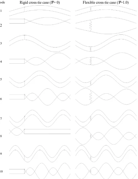
Figure 3.3 Transformation of first ten modes of a symmetric twin-cable network as
flexibility parameter Ψ varies from 0 to 1.0 and cross-tie locates at quarter
span
44
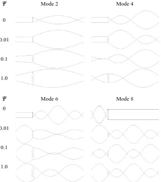
Figure 3.4 Evolution of LS and RS modes of a symmetric twin-cable network with
cross-tie located at quarter span and flexibility parameter ψ varies from 0
to 1.0
46
Figure 3.5 Symmetric SMT two-cable network with unequal length main cables and
flexible cross-tie
47
Figure 3.6 A few typical modes of a symmetric SMT cable network with system
parameters as frequency ratio η2=0.883, segment ratio εj=1/2 (j=1 to 4) and
flexibility parameter ψ=1.0
50
xv cross-tie (ψ=1.0) at =1/3
Figure 3.8 Schematic diagram of the mathematical model for a damped two-cable
network
57
Figure 3.9 Non-dimensional modal damping ratio as a function of the
non-dimensional cross-tie position, , for a twin-cable network
66
Figure 3.10 Mode shapes (real part) of global and local modes having the same modal
frequency and modal damping: a) ε=1/3, b) ε=1/2, c) ε=3/4
68
Figure 3.11 Selected modes (real part) of a twin-cable network with a rigid cross-tie at
1/3 span
70
Figure 3.12 First four modes (real part) of a symmetric DMT two-cable system with a
rigid cross-tie at mid-span
74
Figure 3.13 Non-dimensional damping ratio of the fundamental mode as a function of
non-dimensional damping relation parameter for a symmetric DMT
two-cable network
76
Figure 3.14 Non-dimensional damping ratio of the fundamental mode as a function of
cross-tie position for a symmetric DMT two-cable network
77
Figure 3.15 Optimum cross-tie position range for a symmetric DMT two-cable network 79
Figure 3.16 First ten modes of an asymmetric two-cable system with a rigid cross-tie at
three-quarter span
84
Figure 3.17 Optimum cross-tie position range for an asymmetric two-cable network 86
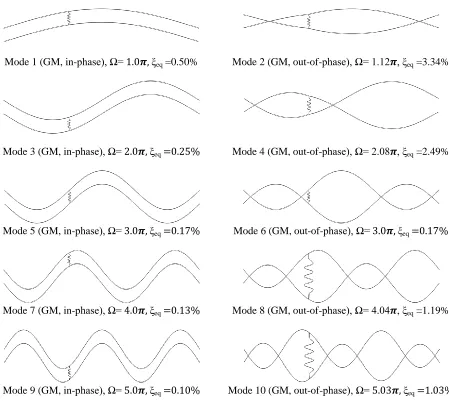
Figure 3.18 First ten modes of a twin-cable network with a damped flexible cross-tie
(Kc=30.54 kN/m, Cc=1.0 kN·s/m) at =1/3
92
Figure 3.19 First ten modes of a twin-cable network with a damped flexible cross-tie
(Kc=30.54 kN/m, Cc=1.0 kN·s/m) at =2/5
95
Figure 3.20 First ten modes of a symmetric DMT two-cable network with a damped
flexible cross-tie (Kc=30.54 kN/m, Cc=1.0 kN·s/m) at =1/2
100
Figure 3.21 First ten modes of an asymmetric DMT two-cable network with a damped
flexible cross-tie (Kc=30.54 kN/m, Cc=1.0 kN·s/m) at =1/3
104
Figure 3.22 Effect of undamped cross-tie stiffness parameter ψo on modal frequency
xvi
modes of an asymmetric DMT cable network
Figure 3.23 Effect of cross-tie damping coefficient C on modal frequency and modal
damping ratio of the lowest in-phase and out-of-phase global modes of an
asymmetric DMT cable network
107
Figure 4.1 Schematic diagram of general cable network with multiple lines of
cross-ties
111
Figure 4.2 First ten modes of five-cable network with two lines of flexible cross-ties
(ψ1= ψ2=0.01) at a position of ε1,1=ε1,2=1/3
117
Figure 4.3 The ‘‘AS-line’’ unit on the south tower of the Fred Hartman Bridge
(Caracoglia and Zuo, 2009)
119
Figure 4.4 First ten modes of the cable network on the Fred Hartman Bridge with
three lines of cross-ties (ψ1= ψ2= ψ3=0.01) at a position of ε1,1=ε1,2=
ε1,3=1/3
121
Figure 5.1 Schematic diagram of two-cable network with two transverse cross-ties 129
Figure 5.2 First ten modes of two-cable network with two lines of flexible cross-ties
(ψ1=ψ2=0.1) at a position of ε1=0.35 and ε2=0.25
133
Figure 5.3 Schematic layout of Networks A to C used for the understanding of mode
localization
137
Figure 5.4(a) Non-dimensional fundamental frequency, / , and its degree of mode
localization, as a function of frequency ratio parameter for Networks A, B
and C with non-dimensional cross-tie flexibility parameter Ψ=0.01 and
mass-tension ratio parameter γ2=0.85.
139
Figure 5.4(b) Non-dimensional fundamental frequency, / , and its degree of mode
localization, as a function of frequency ratio parameter for Networks A, B
and C with non-dimensional cross-tie flexibility parameter Ψ=1.0 and
mass-tension ratio parameter γ2=0.85.
139
Figure 5.5(a) Non-dimensional frequency, / , and its degree of mode localization, as a
function of frequency ratio parameter for Modes 2, 3 and 4 in Network A
with non-dimensional flexibility parameter Ψ=0.01 and mass-tension ratio
parameter γ2=0.85.
141
xvii
function of frequency ratio parameter for Modes 2, 3 and 4 in Network B
with non-dimensional flexibility parameter Ψ=0.01 and mass-tension ratio
parameter γ2=0.85.
Figure 5.5(c) Non-dimensional frequency, / , and its degree of mode localization, as a
function of frequency ratio parameter for Modes 2, 3 and 4 in Network C
with non-dimensional flexibility parameter Ψ=0.01 and mass-tension ratio
parameter γ2=0.85.
142
Figure 5.6 Mode cross-over behaviour of Mode 2 and Mode 3 in Network A with
non-dimensional flexibility parameter Ψ=0.01 and mass-tension ratio
parameter γ2=0.85.
144
Figure 5.7 Non-dimensional frequency, / , and its degree of mode localization, as a
function of mass-tension ratio parameter for Networks A, B and C with
frequency ratio η2=0.92 and cross-tie non-dimensional flexibility Ψ=0.01.
146
Figure 5.8(a) Non-dimensional frequency, / , and its degree of mode localization, as a
function of mass-tension ratio parameter for Modes 2, 3 and 4 in Network
A with frequency ratio η2=0.92 and cross-tie non-dimensional flexibility
Ψ=0.01.
147
Figure 5.8(b) Non-dimensional frequency, / , and its degree of mode localization, as a
function of mass-tension ratio parameter for Modes 2, 3 and 4 in Network
B with frequency ratio η2=0.92 and cross-tie non-dimensional flexibility
Ψ=0.01.
147
Figure 5.8(c) Non-dimensional frequency, / , and its degree of mode localization, as a
function of mass-tension ratio parameter for Modes 2, 3 and 4 in Network
C with frequency ratio η2=0.92 and cross-tie non-dimensional flexibility
Ψ=0.01.
148
Figure 5.9 Non-dimensional frequency, / , and its degree of mode localization, as a
function of cross-tie non-dimensional flexibility parameter for Networks A,
B and C with frequency ratio η2=0.92 and mass-tension ratio γ2=0.85.
150
Figure 5.10(a) Non-dimensional frequency, / , and its degree of mode localization, as a
xviii
and 4 in Network A with frequency ratio η2=0.92 and mass-tension ratio
γ2=0.85.
Figure 5.10(b) Non-dimensional frequency, / , and its degree of mode localization, as a
function of cross-tie non-dimensional flexibility parameter for Modes 2, 3
and 4 in Network A with frequency ratio η2=0.92 and mass-tension ratio
γ2=0.85.
151
Figure 5.10(c) Non-dimensional frequency, / , and its degree of mode localization, as a
function of cross-tie non-dimensional flexibility parameter for Modes 2, 3
and 4 in Network A with frequency ratio η2=0.92 and mass-tension ratio
γ2=0.85.
152
Figure 5.11 Mode “reshaping” of Mode 2 in Network B with frequency ratio parameter
η2=0.92 and mass-tension ratio parameter γ2=0.85.
153
Figure 5.12 Sample layout of cable networks with Configurations A, B and C: (a)
Layout of Configuration A (1,1=0.1, 0.3, 0.5, 0.65 for Network A1, A2, A3
and A4, respectively); (b) Layout of Network B2; (c) Layout of Network
C3
158
Figure 5.13 Effect of cross-tie position on the modal frequency of Networks A1 to A4
(Single line of cross-ties, ψ=0.01): (a) Modes 1-10; (b) Modes 11-20
161
Figure 5.14 Effect of cross-tie position on the fundamental frequency and position of
first LMC (ψ=0.01)
163
Figure 5.15 Effect of cross-ties position on the modal frequency of Network B1 to B5
(two lines of cross-ties, ψ=0.01)
165
Figure 5.16 Effect of cross-tie stiffness on the modal frequency of Network C1 to C3:
(a) Network C1 (Single line of cross-tie evenly installed along main cable
3); (b) Network C2 (Two lines of cross-tie evenly installed along main
cable 3); (c) Network C3 (Three lines of cross-ties evenly installed along
main cable 3)
169
Figure 5.17 Effect of cross-tie stiffness on the fundamental frequency and position of
the 1st LMC of Network C1 to C3: (a) Network C1 (Single line of cross-tie evenly installed along main cable 3); (b) Network C2 (Two lines of
xix
tie evenly installed along main cable 3); (c) Network C3 (Three lines of
cross-ties evenly installed along main cable 3)
Figure 5.18 Effect of number of cross-ties on modal frequency of first 20 modes
(Cross-ties evenly installed along cable 3): (a) ψ=0.01; (b) ψ=0.10
175
Figure 6.1 Non-dimensional fundamental frequency, / , and DML coefficient as a
function of the length ratio parameter, λ, for three different cross-tie
positions: (a) Network-1; (b) Network-2; (c) Network-3
184
Figure 6.2 Non-dimensional fundamental frequency, / , and the DML coefficient as
a function of the length ratio parameter, λ, for four different cross-tie
flexibility parameters (SMT cable network, η2=0.667, ε=1/2)
188
Figure 6.3(a) Non-dimensional fundamental frequency, / , and DML coefficient as a
function of the frequency ratio parameter, η2, for four SMT cable networks
with different number of main cables (n=2, 3, 4, 5) and a rigid cross-tie
installed at the mid-span (ε=1/2)
190
Figure 6.3(b) Non-dimensional fundamental frequency, / , and DML coefficient as a
function of the frequency ratio parameter, η2, for four SMT cable networks
with different number of main cables (n=2, 3, 4, 5) and a rigid cross-tie
installed at the one-third span (ε=1/3)
191
Figure 6.4 Non-dimensional fundamental frequency, / , and DML coefficient as a
function of the frequency ratio parameter η2 for a symmetric SMT
two-cable network with a flexible cross-tie installed at mid-span (ε=1/2, λ2=1.2)
193
Figure 6.5(a) Non-dimensional modified frequency, / , and DML coefficient as a
function of the mass-tension parameter, γ, for four symmetric DMT cable
networks with different number of main cables (n=2, 3, 4, 5) and a rigid
cross-tie installed at mid-span (ε=1/2)
195
Figure 6.5(b) Non-dimensional modified frequency, / , and DML coefficient as a
function of the mass-tension parameter, γ, for four symmetric DMT cable
networks with different number of main cables (n=2, 3, 4, 5) and a rigid
cross-tie installed at mid-span (ε=1/3)
196
Figure 6.6 Non-dimensional fundamental frequency, / , and DML coefficient as a function of
xx
the mass-tension ratio parameter γ for a symmetric DMT two-cable
network with a flexible cross-tie installed at mid-span (ε=1/2, η2=0.833 and
λ2=1.2)
Figure 6.7 Sample layout of cable networks with Configurations A, B, C and D): (a)
Layout of Network A1 in Configuration A; (b) Layout of Network B4 in
Configuration B; (c) Layout of Network C6 in Configuration C; (d) Layout
of Network D6 in Configuration D
203
Figure 6.8 Effect of cross-tie position on the fundamental frequency and position of
the first local mode cluster of Network A (ψ=0.01)
205
Figure 6.9 Effect of cross-tie position on the fundamental frequency and position of
the first local mode cluster of Network Bi (i=1 to 6, ψ=0.01)
206
Figure 6.10 Mode-frequency evolution curves for Networks B1, B3 and B4 (ψ=0.01) 209
Figure 6.11 Effect of cross-tie position on the fundamental frequency and position of
the first local mode cluster of Network Ci (i=1 to 6)
211
Figure 6.12 Effect of cross-tie position on the fundamental frequency and position of
the first local mode cluster of Network Di (i=1 to 6)
211
Figure 6.13 Mode-frequency evolution curves for selected cable networks (three lines
of cross-ties, ψ=0.01)
213
Figure 6.14 Mode-frequency evolution curves for selected cable networks (four lines of
cross-ties, ψ=0.01)
214
Figure 6.15 Mode-frequency evolution curves of the twelve-cable network in different
layouts: (a) Network B4; (b) Network C6; (c) Network D6
217
Figure 6.16 Non-dimensional frequency, / , damping ratio and DML coefficient as a
function of cross-tie stiffness parameter ψ for the fundamental mode of an
asymmetric DMT two-cable network with a flexible cross-tie at one-third
span (ε=1/3)
221
Figure 6.17 Effect of number of cross-tie lines on the modal frequency of the first 50
modes of cable networks A6, B4, C6 and D6): (a) ψ=0.01; (b) ψ=0.10
224
Figure 7.1 Schematic layout of a typical hybrid system with damper installed on main
cable 1
235
xxi
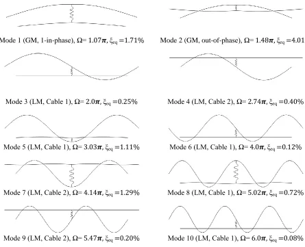
Figure 7.3 First ten modes of a two-cable hybrid network with damper position 1=0.065 and cross-tie position =1/3. (c=19.1 N·s/m, Kc=1210 kN/m)
243
Figure 7.4(a) A taut cable with a transverse linear external viscous damper 248
Figure 7.4(b) A taut cable attached with transverse linear spring and viscous damper 249
Figure 7.4(c) A taut cable attached with two transverse linear viscous dampers 251
Figure 7.4(d) Two-cable hybrid system with external viscous damper on neighboring
cable
252
Figure 7.4(e) Two-cable hybrid system with two external viscous dampers on main cable 256
Figure 7.5 Effect of cross-tie flexibility parameter ψ on the fundamental modal
damping ratio of a two-cable hybrid system (η2=0.80)
262
Figure 7.6 Effect of cross-tie flexibility parameter ψ on the DML coefficient of the
fundamental mode of a two-cable hybrid system (η2=0.80)
264
Figure 7.7 Effect of damper-cross-tie spacing parameter ε1,2 on the fundamental
modal damping ratio of a two-cable hybrid system (η2=0.80)
267
Figure 7.8 Fundamental mode of a two-cable hybrid system for selected values of
cross-tie position and stiffness
270
Figure 7.9 Effect of damper-cross-tie spacing parameter ε1,2 on the DML coefficient
of the fundamental mode of a two-cable hybrid system (η2=0.80)
272
Figure 7.10 Isoquant curves representing in-plane frequency, modal damping ratio and
DML of a two-cable hybrid system fundamental mode (η2=0.80)
275
Figure 7.11 Isoquant curves representing in-plane frequency, modal damping and DML
on ψ-ε1,2 plane of a two-cable hybrid system in the numerical example
279
Figure 7.12 Damping estimation curves for a single damped cable and a symmetric
two-cable hybrid system (ε1,1=0.0235, εc=0.50, η=0.82, λ=1.2 and γ=0.91)
284
Figure 7.13 Damping estimation curves for a single damped cable and a symmetric
two-cable hybrid system (ε1,1=0.0235, ψ=0.0, η=0.82, λ=1.2 and γ=0.91)
288
Figure 8.1 Experimental setups of three different systems: (a) Cable network; (b)
Hybrid system A; (c) Hybrid system B
299
Figure 8.2 Passive linear viscous damper 303
Figure 8.3 Universal Flat Load Cells mounted at the cable ends 304
xxii
Figure 8.5 Electronic dynamic smart shaker installed on the target cable (bottom
cable)
306
Figure 8.6 HP signal generator for dynamic smart shaker 307
Figure 8.7 PC-based AstroDAQ Xe data acquisition system 308
Figure 8.8 Cross-tie connected with the main cables 310
Figure 8.9 Half-power method used to calculate the damping ratio 315
Figure 8.10 A fraction of sample acceleration time history raw data of the cable
network (rigid cross-tie located at 1/4L)
317
Figure 8.11 Power spectral density curve of the cable network (rigid cross-tie located at
1/4L)
318
Figure 8.12 Extracted fundamental modal displacement time history of the cable
network (rigid cross-tie located at 1/4L)
318
Figure 8.13 In-plane fundamental frequency of a two-cable network as a function of
cross-tie position εc (η=0.79)
322
Figure 8.14 Fundamental modal damping ratio of a two-cable network as a function of
cross-tie position εc (η=0.79)
322
Figure 8.15 Frequency-response curve of hybrid system A (rigid cross-tie located at
1/4L)
328
Figure 8.16 Figure 8.16: In-plane fundamental frequency of a two-cable hybrid system
A as a function of cross-tie position εc (η=0.79)
333
Figure 8.17 Fundamental modal damping ratio of a two-cable hybrid system A as a
function of cross-tie position εc (η=0.79)
334
Figure 8.18 In-plane fundamental frequency of a two-cable hybrid system B as a
function of cross-tie position εc (η=0.79)
338
Figure 8.19 Fundamental modal damping ratio of a two-cable hybrid system B as a
function of cross-tie position εc (η=0.79)
xxiii
LIST OF TABLES
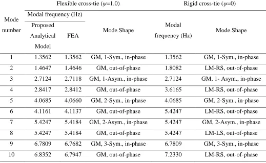
Table 3.1 Comparison of in-plane modal properties of a symmetric twin-cable
network with rigid (ψ=0) and flexible (ψ=1.0) cross-tie at quarter span
42
Table 3.2 In-plane modal properties of a symmetric unequal length two-cable network
with system parameters as frequency ratio η2=0.88, segment ratio j=1/2
(j=1 to 4), mass-tension ratio γ1=γ2=1 and flexibility parameter ψ=1.0
48
Table 3.3 Comparison of modal properties of an asymmetric DMT two-cable network with flexible or rigid cross-tie at =1/3
51
Table 3.4 In-plane modal frequency and modal damping of a twin-cable network with
a rigid cross-tie at one-third span
68
Table 3.5 In-plane modal frequency and modal damping of a symmetric two-cable
network with a rigid cross-tie at mid-span
71
Table 3.6 In-plane modal frequency and modal damping of an asymmetric two-cable
network with a rigid cross-tie at three-quarter span
82
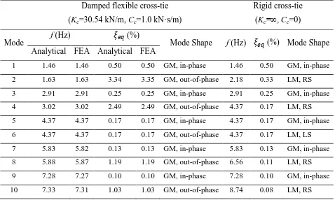
Table 3.7 Comparison of modal properties of a twin-cable network with damped flexible or rigid cross-tie at =1/3
90
Table 3.8 Comparison of modal properties of a twin-cable network with damped flexible or rigid cross-tie at =2/5
93
Table 3.9 Comparison of modal properties of a symmetric DMT two-cable network with damped flexible or rigid cross-tie at =1/2
98
Table 3.10 Comparison of modal properties of an asymmetric DMT two-cable network with damped flexible or rigid cross-tie at =1/3
102
Table 4.1 Modal properties of a general five-cable network with two lines of flexible
cross-ties (ψ1= ψ2=0.01) evenly installed along the target cable
(ε1,1=ε1,2=1/3)
117
Table 4.2 Physical properties of main cables in the “A-line’’ unit of main span of the
Fred Hartman Bridge
118
Table 4.3 Modal properties of ‘‘A-line’’ cable network at Fred Hartman Bridge with
two lines of flexible cross-ties (ψ1= ψ2=0.01) evenly installed along the
xxiv target cable (ε1,1=ε1,2=1/3)
Table 5.1 Modal properties of a general two-cable network with two lines of flexible
cross-ties at a position of ε1=0.35 and ε2=0.25 (ψ1=ψ2=0.1)
133
Table 5.2 Non-dimensional modal frequencies of cable networks A1 to A4 (Single line of cross-ties, ψ=0.01)
159
Table 5.3 Summary of local mode cluster and pairs of local modes for cable networks B1 to B5
164
Table 5.4 Summary of local mode cluster and pairs of local modes for cable network C1
169
Table 5.5 Summary of local mode cluster and pairs of local modes for cable network C2
170
Table 5.6 Summary of local mode cluster and pairs of local modes for cable network C3
170
Table 6.1 Summary of fundamental frequency, the first local mode cluster and pairs of local modes within the first 30 modes of cable networks B1 to B6
206
Table 6.2 Summary of fundamental frequency, the first local mode cluster and pairs of local modes within the first 30 modes of cable networks C1 to C6
211
Table 6.3 Summary of fundamental frequency, the first local mode cluster and pairs of local modes within the first 30 modes of cable networks D1 to D6
211
Table 6.4 Summary of the fundamental frequency, the first local mode cluster and pairs of local modes within the first 30 modes of cable networks B4, C6 and D6
217
Table 6.5 Summary of non-dimensional system frequency and the first local mode cluster attributes for four optimized cable networks in term of positions of cross-ties within the first 50 modes
222
Table 7.1 Fundamental modal frequency and damping ratio of isolated cables and hybrid system with damper position l1,1=0.55m (1=0.065) and cross-tie
position =1/3 (c=19.1 N·s/m, Kc=1210 kN/m)
240
Table 7.2 Modal properties of the two-cable hybrid system in the numerical example 241
Table 7.3 The optimum damper size and the maximum attainable fundamental modal damping ratio of a single damped cable and a symmetric two-cable hybrid system (ε1,1=0.0235, εc=0.50, η=0.82, λ=1.2 and γ=0.91)
284
Table 7.4 The optimum damper size and the maximum attainable fundamental modal damping ratio of a single damped cable and a symmetric two-cable hybrid system (ε1,1=0.0235, ψ=0.0, η=0.82, λ=1.2 and γ=0.91)
288
Table 8.1 Physical properties of the main cables 301
Table 8.2 Material properties of the cross-ties 301
xxv
Table 8.4 List of testing cases conducted for the modal behaviour of hybrid system A (external damper position =0.55 m (0.065%L))
311
Table 8.5 List of testing cases conducted for the modal behaviour of hybrid system B (external damper in-line with the cross-tie)
312
Table 8.6 Fundamental frequency of a two-cable network with different cross-tie positions (Hz)
319
Table 8.7 Fundamental modal damping ratio of a two-cable network with different cross-tie positions (%)
319
Table 8.8 Material and geometric properties of main cables and cross-tie as non-dimensional parameters
319
Table 8.9 Maximum displacement at each excitation frequency of the shaker in hybrid system A (rigid cross-tie located at 1/4L)
326
Table 8.10 Fundamental frequency of hybrid system A for different positions of cross-tie (damper installed at 0.065%L*) (Hz)
329
Table 8.11 Fundamental modal damping ratio of hybrid system A for different positions of cross-tie (damper installed at 0.065%L*) (%)
329
Table 8.12 Fundamental frequency of hybrid system B for different positions of cross-tie (Hz)
334
Table 8.13 Fundamental modal damping ratio of hybrid system B for different positions of cross-tie (%)
1
CHAPTER 1
Introduction
1.1 Background
The original concept of using cable stays can perhaps be dated back to ancient Egypt. In
the construction of sailing ships, inclined ropes hanging from a mast were used to support a basin
beam (Troitsky, 1977). Similarly, in some tropical regions, bamboo sticks were used to support
pedestrian bridge deck and with the other end of the sticks attached to a tree. Although simple
bridges with deck supported by inclined bars or chains were designed in the 17th century (Leonhardt and Zellner, 1991), the first cable-stayed bridge, Roeblings Bridge, was not
constructed until the 19th century. However, limited by the availability of high strength materials, analysis methods, and construction techniques, the idea of cable-stayed bridge was abandoned
for some time. The rebooming of cable-stayed bridge occurred after the Second World War,
when German engineers faced the challenges to replace many bridges destroyed during the war
by innovative and inexpensive solutions. In the past two decades, the span length of cable-stayed
bridges has been increasing rapidly. The Russky Bridge in Russia, the world’s longest
cable-stayed bridge at present, has a central span length of 1104 m with the longest cable being 580 m;
whereas the second longest cable-stayed bridge, the Sutong Bridge in China, has a central span
length of 1088 m (Weber and Distl, 2015). The world’s tallest bridge, the Millau Viaduct Bridge
in southern France, also belongs to the family of cable-stayed bridge. It has an impressive height
of 343 m. The growing popularity of cable-stayed bridges is due to its aesthetic, ease of deck
erection, economics, small deflection and effectiveness in poor soil condition in comparison to
suspension bridges (Bimson, 2007).
However, these encouraging breakthroughs come at a price and present new challenges to
2
slender and flexible structural components. In particular, with the growth of bridge span length,
stay cables are becoming longer. The longest cable on the Rusky Bridge has a length of 580 m.
Further, stay cables are key structural components of cable-stayed bridge. They are subjected to
high pre-tension forces. By applying initial tension, the friction force between the wires or
strands composing a stay cable changes considerably which significantly reduces the structural
damping of the cables (Hard and Holben, 1967; Yamaguchi and Fujino, 1987; Yamaguchi and
Nagahawatta, 1995). A study conducted by Hard and Holben (1967) revealed that a significant
reduction in the logarithmic decrement of cable oscillation amplitude was observed as the cable
tension increased from 20% to 40% of the rated strength and the reduction rate in cable structural
damping dropped with the increase of cable tension. Yamaguchi and Adhikari (1995) pointed out
that structural damping of a stay cable without initial pretension could be ten times than that of
an initially stressed cable. Field data collected from measurements indicated that the intrinsic
structural damping ratio of the majority of stay cables was typically less than 0.3% (Meharabi,
2006). Therefore, under the combined effects of low inherent structural damping and long
flexible feature, stay cables are prone to dynamic excitations due to various environmental
factors, such as wind, wind combined with rain, earthquake and nonlinear coupling between
motions of cables, deck and/or pylon (Virlogeux, 1998).
In the past few decades, many violent cable vibration incidents were reported from
different bridge sites. The first recorded large amplitude cable vibration was on the Brottonne
Bridge in 1977. Later, similar phenomenon was also reported from the Ben Ahin Bridge in
Belgium, the Farø Bridge in Denmark and the Glebe Island Bridge in Australia (Virlogeux,
1998). Maximum cable vibration amplitude of 0.6 m was recorded on the Burlington Bridge in
3
(RWDI) on the Cochrane Bridge in Alabama reported a first modal cable vibration amplitude
close to 0.5 m at moderate wind speed of 8 m/s to 10 m/s when accompanied by light rain
(Lankin et al., 2000). In a full-scale measurement on the Fred Hartman Bridge conducted by
Ozkan et al. (2001), peak-to-peak cable vibration amplitude of 1 m was reported during the
passage of a heavy storm. In 2005, almost all the stay cables on the Dubrovnik Bridge in Croatia
experienced violent vibration with a disturbing rattling noise (Savor et al., 2006). The cable
vibration amplitudes were so large that even the light posts located at a distance 85 cm away
were broken down. In Japan, violent cable vibration amplitude of more than 1.5 m occurred on a
cable-stayed bridge during passage of a typhoon and the external damper attached to the cable
was found to be damaged (Matsumoto et al., 2010). In the case of the Alamillo Bridge in Spain,
transverse vibration amplitude of 0.5 m was observed for the longest cable on a rainy day, when
the wind speed was at 15 to 20 m/s (Casas and Aparicio, 2010). The stay cables can also be
excited due to the motion of stay supports or decks when the global frequency of the decks falls
close to the natural frequency of some of the stay cables (Wu et al., 2003; Cao et al., 2012).
1.2 Types of wind-induced cable vibrations
Depending on their mechanisms, the wind-induced cable vibrations mostly related to stay
cables can be categorized as the following types:
a) Rain-wind-induced vibration
It is believed that this type of vibration is mainly caused by the formation of water
rivulets on the surface of inclined cables. The mechanism of rain-wind-induced vibration has not
been fully understood yet and research is still needed. Usually two types of rivulets are formed,
one on the top of the cable surface at the windward side and the other on the bottom surface at
4
aerodynamic force on the cable. The presence of the water rivulets would not only change the
effective cross-sectional shape of the cable but also oscillates on its surface as it vibrates. The
resonance between the motions of the cable and the water rivulets amplifies the vibration
amplitude of the cable. The majority of cables that experienced this type of vibration are located
on the leeward side of the bridge pylon and geometrically declined in the mean wind direction.
The formation of upper water rivulet on the cable surface seems to be a key factor (Yamada et
al., 1997). The number of dominant modes generally ranged from 1 to 4, with most of the
responses occurred in Mode 2 and Mode 3 (Zuo and Jones, 2010). The frequencies of the
dominant modes are distributed over a relatively wide range mostly between 1 and 3 Hz (Main et
al., 2001) in moderate to heavy rain within a wind speed range of 5–15 m/s (Phelan et al., 2006;
Caetano, 2007). However, some cable vibrations are also reported to occur at wind speeds as
high as 40 m/s (Zuo and Jones, 2010). It is worth pointing out that about 95% of the reported
stay cable vibration incidents are due to the rain-wind induced vibration (Wagner and Fuzier,
2003).
b) Vortex-induced vibration
When wind blows past a cable, vortex would form and shed alternatively in its wake.
This would generate alternating low-pressure zones on the downstream side of the cable. Cable
tends to move toward the low-pressure zone and thus would oscillate according to vortex
shedding frequency. If the natural frequency of the cable lies in the close proximity of the
shedding frequency of the vortices, resonance would occur and results in high amplitude cable
vibrations. These vibrations are generally observed in the higher modes typically Mode 5 and
up. Although the displacement amplitude of these higher modes is relatively small (20% of the
5
oscillation frequencies (Main et al., 2001; Zuo and Jones, 2010). This type of vibration is
potentially less damaging, mainly because of its small vibration amplitude, than rain-wind
induced or galloping vibration (Mehrabi, 2006). When investigating the cause of the original
Tacoma Narrows Bridge failure in 1940, vortex-induced vibration was proposed as one of the
possible mechanisms but was dismissed since the frequency of the vortex shedding did not match
with that of the bridge.
c) Buffeting
This type of wind-induced cable vibration is due to the velocity fluctuation in the
oncoming flow and is directly related to the level of wind speed. Buffeting has not been found to
cause serious problems on bridge stay cables. However, this frequent low amplitude vibration
could induce fatigue damage at the cable anchorage and thus threat the safety of bridges.
d) Wake Galloping
When a cable is submerged in the wake of other elements, such as towers or other cables,
if the vortex shedding frequency of an upstream body is in resonance with the natural frequency
of the cable, large amplitude of wake galloping would be excited. The cable oscillates along an
elliptical trajectory. Cooper (1985) proposed a stability criterion which could predict the critical
value of the wind velocity Ucrit above which instability could be expected due to wake galloping
effects.
e) High-speed vortex excitation
High-speed vortex excitation is directly associated with the formation of the axial flow on
the leeward side of an inclined cable. The phenomenon was observed in field and in wind tunnel
tests. It occurs at much higher wind velocity ranges than that for regular vortex-induced
6
interacts with that of the axial vortex, which induced amplified response. Though the mechanism
of this phenomenon is not fully understood, observations showed that the frequency seemed to
be about one-third of the Kármán vortex shedding frequency. Caetano (2007) showed that its
occurrence also depends on some other factors like cable orientation and frequency of cable
vibration.
f) Dry inclined cable galloping
Dry inclined cable galloping is an excitation phenomena identified by Saito et al., (1994),
Honda et al., (1995) and Cheng et al., (2003) during wind tunnel tests but no formal confirmed
field incident has been reported yet. When a single inclined cable is exposed to wind, wind
“sees” an elliptical cable cross-section instead of a circular one. When entering into the critical
Reynolds number regime, there is a potential to trigger galloping type instability if the level of
structural damping in the cable is very low. One of the possible mechanisms is proposed to be
linked to the occurrence of negative aerodynamic damping in the critical Reynolds number range
(Cheng et al., 2008a; 2008b). Research about this phenomenon and its driven mechanism is still
undergoing.
It is worth pointing out that among these different types of wind-induced cable vibrations,
rawind-induced vibration is the most frequently observed one. Most of the time, it is an
in-plane oscillation and occurs at moderate wind speed with the presence of light rain (Lankin et al.,
2000).
1.3 Countermeasures
Suppressing vibrations of bridge stay cables is of prime importance since stay cables are
the key structural elements of a cable-stayed bridge. Frequent and/or excessive vibrations of stay
7
and ultimately reducing the life of stay cables (Johnson et al., 2002). Consequently, it would
have a considerable impact on the serviceability and life span of the entire bridge.
To control cable vibrations, different countermeasures are adopted, which can be
classified as aerodynamic type and mechanical type. The aerodynamic type of countermeasures
aims at changing aerodynamic behaviour of stay cables by modifying their surface conditions or
cross-sectional shape. Experimental results showed that by wrapping spiral wire around cable
surface (Bosdogianni and Olivari, 1996; Zhan et al., 2008) or making dimpled surface
(Virlogeux, 1998), rain-wind-induced cable vibrations could be effectively suppressed. The
helical wire whirling surface has now become a standard requirement of manufacturing stay
cables. Some researchers also recommended wrapping stay cables with viscoelastic damping
tapes and providing neoprene rubber bushings (or rings) (Tabatabai and Mehrabi, 2000a). The
neoprene rubber bushings do not only contribute to the damping of the vibrating cables but are
also effective in reducing bending stresses at the anchorages (Takano et al., 1997). One of the
main purposes of these surface treatments is to prevent the formation of water rivulets, which is
the main cause of rain-wind-induced vibration. Some of the well-known aerodynamic
countermeasure examples, in terms of cable surface treatment, are the axial protuberance
installation on the Higashi Kobe Bridge; the dimple distribution on the Tatara Bridge and the
helical wire installation on the Normandy Bridge (Matsumoto et al., 2003). However, these
surface treatments cannot provide additional damping to the cable and are difficult to be applied
to existing structures. In addition, evidence showed that surface treatment might increase drag on
stay cables and so it could become more significant in the case of long span cable-stayed bridges
8
On the other hand, mechanical type of countermeasures is directed to enhance either
energy dissipation or stiffness of cable(s). External dampers installed near the cable-deck
anchorage are used to help dissipate kinetic energy of an oscillating cable and thus increase
structural damping of the attached cable (Pacheco et al., 1993; Krenk, 2000; Tabatabai and
Mehrabi, 2000b; Zhan et al., 2008; Cheng et al., 2010). External dampers are more effective for
stay cables on small to medium-span cable-stayed bridges. However, their efficiency is limited in
the case of long-span bridges such as the Normandy Bridge in France and the Sutong Bridge in
China due to the longer cables length and constrains on damper installation location. For
example, by installing an external viscous damper, if it is expected that the damped cable should
achieve a maximum equivalent modal damping ratio of 1% for the fundamental mode of a stay
cable with a length of 500 m, the damper would have to be attached at a distance of 10 m from
the cable anchorage, which may not be feasible in practice. It is also observed that external
dampers installed near the cable-deck anchorage are not activated in case of small amplitude
cable vibrations. Besides, it is also important to note that external dampers are delicate devices
that require constant maintenance. More recently, researchers are also exploring new methods to
mitigate violent cable vibrations. For example, to suppress cable vibrations by the application
and removal of constraints dynamically during cable vibrations (Alsahlani et al., 2012).
Cross-tie solution is another mechanical countermeasure. It is becoming more popular in
recent years on new bridges (Kangas et al., 2012) and in the rehabilitation of existing ones
(Mehrabi et al., 2010). In this solution, a cable which has exhibited or is expected to experience
large amplitude vibrations is interconnected with its neighbouring cable(s) through transverse
secondary cables, i.e. cross-ties, to form a cable network. It is understood from past studies that a
9
in-plane stiffness (Caracoglia and Jones, 2005a) and thus increase the frequency of cables. This
cannot only increase the critical onset wind speed of many wind-induced cable vibration
phenomena, but also avoid parametric excitation caused by the bridge deck oscillation as was the
case for the Normandy Bridge in France (Virlogeux, 1998); b) Introduce additional structural
damping (Yamaguchi and Jayawardena, 1992; Yamaguchi and Nagahawatta, 1995; Lankin et al.,
2000); c) Redistribute energy into higher modes or other cables in the same network (Ehsan and
Scanlan, 1989; Yamaguchi and Nagahawatta, 1995); d) Increase modal mass of the global
modes. This would help to increase Scruton number in these lower order modes (Kumarasena et
al., 2007). In order to suppress rain-wind-induced cable vibrations, a minimum required Scruton
number of 10 is recommended (Kumarasena et al., 2007); e) Help to avoid wake galloping effect
in the case of twin-cable networks (Virlogeux, 1999); f) Reduce cable sag variation among stays
of different lengths (Gimsing, 1993).
So far, cross-ties have been successfully used on a number of cable-stayed bridges to
control cable vibrations. They include the Farø Bridge in Denmark, the Normandy Bridge in
France (Virlogeux, 1993), the Yobuko Bridge in Japan (Yamaguchi, 1995), the Fred Hartman
Bridge (Caracoglia and Jones, 2005b), the Dames Point Bridge (Kumarasena et al., 2007) and the
newly constructed U.S. Grant Bridge (Kangas et al., 2012) in the United States. After installing
the cross-ties on the Farø Bridge, cable oscillations were reduced to an acceptable level for all
cables in the network except the first cable on each side of the pylon due to special wind
condition on these cables (Bloomstine and Stoltzner, 1999). Similarly, no problematic cable
vibrations have been reported on the Second Severn Bridge in the United Kingdom after using
the cross-tie solution (Stubler et al., 1999). The Texas Department of Transportation (Texas
10
Bridges after receiving calls from the public about observed excessive cable vibrations (Ramsey,
2005). Based on the study recommendation, a cross-tie solution was proposed for the Fred
Hartman Bridge and cable vibrations were reduced significantly. When the cross-tie system was
uninstalled for the purpose of maintenance and improvement, excessive cable vibrations
appeared again, proving the effectiveness of the cross-tie solutions (Ramsey, 2005).
On the other hand, there are some disadvantages of the cross-tie solution apart from the
above mentioned benefits. One of the major drawbacks is the appearance of closely spaced
higher order local modes (Caracoglia and Jones, 2005b; Bosch and Park, 2005). These densely
populated local modes impose a potential risk to cable network for its sensitivity to dynamic
excitations within a narrow frequency band. Due to inherent nature of cable networks, it is
almost impossible to eliminate these closely spaced local modes. However, by a careful selection
of cross-tie properties, it is possible to shift these local modes to higher order. In addition, it is
also important to note that although cross-ties can increase damping of a cable network
(Yamaguchi and Jayawardena, 1992; Yamaguchi and Nagahawatta, 1995; Lankin et al., 2000),
they are not primary energy dissipating devices and cannot control out-of-plane cable vibrations
(Caracoglia and Jones, 2005b).
The main objective of external dampers is to increase structural damping of stay cables,
and therefore suppressing undesirable cable vibrations. External dampers are effective as long as
a stay cable is not too long and the damper is activated at the proper time. From field
observations, it is known that external viscous dampers would not be activated for small
amplitude cable vibrations. In the case of cross-tie solution, the main objective is to increase the
modal mass and the in-plane stiffness of the network global modes but cannot be used as a direct
11
merits and limitations. Therefore, some researchers proposed to combine them into a single
hybrid device/system. Some of the well-known examples of hybrid system applications include
the Normandy Bridge in France (Virlogeux, 1993) and the Fred Hartman Bridge in USA
(Caracoglia and Jones, 2005b). On both bridges, it was reported that the hybrid system worked
successfully.
Nevertheless, there are only limited numbers of studies available in the literature which
has investigated the mechanics of such a hybrid system. Bosch and Park (2005) used finite
element simulations to explore the performance of hybrid system. Results showed that the
cumulative benefits of both cross-ties and external dampers would not necessarily to earn the
same benefits when applying separately. The study by Caracoglia and Jones (2007) revealed that
hybrid system was not able to control the formation of local modes. Caracoglia and Zuo (2009)
investigated the effectiveness of hybrid system with different configurations. It was found that
the configuration of external damper in-line with the cross-tie line was more effective than that
of the external dampers installed close the anchorage of the target cable. More recently, Zhou et
al. (2015) developed an analytical model of a symmetric two-cable hybrid system, of which the
two consisting cables were laid in parallel with each other and connected by a transverse spring.
In addition, each of them was attached with a linear viscous damper close to one end. A free
vibration analysis was performed to understand the modal behaviour of such a hybrid system, in
terms of its in-plane frequency and modal damping associated with the second in-phase and
out-of-phase modes when the two main cables were identical. Unfortunately, the hybrid systems
discussed in these few existing studies were either based on the cable layout on a particular
cable-stayed bridge, or has an idealized symmetric configuration, of which some findings might
12
focused on investigating the in-plane stiffness and damping of the hybrid system, whereas the
severity of local mode formation was completely neglected. Therefore, more intensive studies,
preferably using analytical approach, are urgently needed to better understand the mechanics of
hybrid systems.
1.4 Motivations
In spite of an increasing popularity of the cross-tie application and its proven
effectiveness on site, there were numerous cross-tie failure breakage incidents occurred on
different bridges. The first two reported cross-tie breakage incidents happened on the
Saint-Nazaire Bridge in France and the Zarate Brazo Largo Bridge in Argentina (Virlogeux, 1998). In
the case of the Farø Bridge in Denmark, rupture occurred twice on one of the cross-ties and a
few others were seriously damaged (Bloomstine and Stoltzner, 1999). Similar incidents were
also reported from the Meiko Nishi Bridge and the Yuboko Bridge in Japan (Virlogeux, 1998;
Noguchi and Miyauchi 2010); the Burlington Bridge (Zuo and Jones, 2005) and the Fred
Hartman Bridge in USA (Ramsey, 2005). All these incidents show that there is a lack of
thorough understanding of the mechanics of cable networks.
The majority of the existing analytical studies on cable networks were based on simple
network configuration containing a single line of cross-tie(s), whereas in practice, cable networks
on real bridges usually possess at least two lines of cross-ties. The addition of another line of
cross-tie(s) would considerably increase the complexity of network behaviour and make it very
challenging in the analysis. To have a comprehensive understanding of the dynamic behaviour of
cable networks, there is a great need to develop an analytical model of a general cable network