SDFT Based Fault Detection Technique on
Distribution System in a Smartgrid with
Distributed Generation Sources
Dipak R.Narkhede 1, Dr. V. A. Kulkarni2
M. E. Student, Department of Electrical Engineering, Government College of Engineering, Aurangabad, MS, India
Associate Professor, Department of Electrical Engineering, Government College of Engineering, Aurangabad,
MS, India2
ABSTRACT:An accurate method for fault distance calculation in electrical power distribution systems in a Smartgrid
with Distributed Generation (DG) sources is proposed. Distribution line faults affect the reliability of the service to the customer, the stability of the power system and the quality of the power delivered. The reason to develop new method is a precise estimation of the fault location,which make an easier task for maintenance person.
A wide spectrum of signals that contains information about the fault distance is produce when a fault is occure. Synchronized voltage and current samples at sending & receiving ends of a protected zone are used to estimate the location of the fault. This paper proposes Smart Discrete Fourier Transform, SDFT to extract accurate fundamental frequency components for calculation of fault location index. Results have shown that the SDFT based method can extract exact phasor in the presence of frequency deviation and harmonics. The simulations are carried out using MATLAB software. Results of simulation for different types of faults shows accuracy of the proposed method.
KEYWORDS:Distributed Generation (DG), Smart Grid, Microgrid, Smart Discrete Fourier Transform (SDFT),
Distribution System, Phasor Measurement Unit (PMU) and Fault Analysis.
I.INTRODUCTION
Electric power distribution systems are subjected to faults caused by different reasons like foul weather conditions, insulation failure, traffic accidents, etc [9]. To improve the service reliability, it is necessary for the utility to identify the fault location as quickly as possible when fault is incident on the distribution network. Most of the research mentioned above focuses on the fault location of the transmission lines. It is because transmission networks are generally under the balanced operation that enables the circuit analysis based on the symmetrical component. The sequence component method generates three independent sequence networks only in case of the balanced systems and becomes a powerful tool in the circuit analysis. However, it cannot be applied to the distribution system case, since most distribution systems are unbalanced due to the mixed use of single phase and three phase laterals and loads, etc. Although a direct circuit analysis of three phase network is another alternative but it has not been considered due to its high complexity and difficulty during the course of analysis. This is why not much researchon the fault location problem has been reported for the distribution system. A fast fault location helps in reducing the interruption time,but typical visual examination not solely takes an exended time however additionally needs high work force. Fast restoration of service might reduce complaints, outage time & revenue loss.
harmonics. Fault location methods for the unbalanced distribution systems utilize harmonics, fundamental component of voltage and current. Fault location methods in distribution systems can be divided into two main categories: impedance based methods and traveling wave based methods. Impedance based methods estimate the Fault location based on the impedance estimation from the fault locator point [25].
Now a days we need reliable & efficient system this can be possible by adding state of the art electronic & electrical devices , parts & algorithms. The base of the system is the decentralization of existing power grid into smaller grid (Microgrid) with Distributed Generation (DG) sources connected. This new system is known as “Smart Grid”. One critical problem due to these integrations is excessive increase in fault current due to the presence of DG within a microgrid [17]. In a smartgrid grid network is decentralized into smaller grids, which are called as microgrids, with DG sources connected to them. These microgrids may or may not be connected with conventional power grid, but the need to integrate various kinds of DGs and loads with safety should be satisfied. Excessive increase in fault current and the islanding are two major challenging issues in direct connection of DGs with the power grid which is caused when, despite a fault in the power grid, DG keeps on providing power to fault state network [19].To address these issues the design of such grid will be based on inter-disciplinary knowledge in the area of communication engineering, optimization, control, social and environmental constraints.[13]. Figure 1 shows significant functional elements of smart grid design.
Fig. 1. Smart Grid Intelligent automation functions [13].
In power systems, phasors are used for analyzing AC quantities with the assumption that frequency is constant. A relatively new variant of this technique that synchronizes the calculation of a phasor to absolute time has been developed, called “Synchronized Phasor Measurement” or “Synchrophasor”. Recent Developement in Microprocessor based relays, Global Positioning System (GPS) receivers for synchronization as well as exact time stamping, assist in modern relay systems with synchronized measurements, known as ‘synchrophasor measurements’. This Synchrophasor measurements with the help of modern communication provide users the state of a power system 20 times each second.
(SDFT) digital algorithm is presented, it can give accurate solution even when frequency deviates from nominal frequency. It is faster than DFT, and it can give exact solution in the presence of harmonics. In this paper, proposed a SDFT method for estimation of real time and accurate the power system frequency. Simulation results confirm the validity and efficiency of the SDFT method to achieve real time estimation of the power system frequency [16].
II.RELATEDWORK
Guidelines towards the techniques and application considerations for determining the location of a fault on ac transmission and distribution lines are outlined in IEEE Standard IEEE Std C37.114™-2014 (Revision of IEEE Std C37.114-2004),[1].Several investigations have examined the fault detection andlocation in transmission and distribution lines. Among these investigationsJoe-Air Jianget al[2],[8] uses parameter estimation algorithm and SDFT methodto determine a fault detection/location index in termsof Clarke components of synchronized phasor measurements. Seung-Jae Leeet al [9] proposed fault location algorithm which identifiesfault locations using an iterative estimation of load current and fault current at each line section. The diagnosis part determines the actual location by comparing the current waveform pattern with the expected patterndue to operation of the protective devices. Myeon-Song Choiet al [11] uses application of the matrixinverse lemma to simplify fault location algorithm based on the direct circuitanalysisfor unbalance distribution system. Wang, Luiet al [15]discuss a fault location method for new protectionscheme of distribution system in which faulted section was identifed with loadingconditions considered in an iterative manner. Afer the faultedsection was identifed, fault location was calculated fom thevoltage equality condition. Jun-Zhe Yanget al.[16] proposed Smart Discrete Fourier Transforms (SDFT)to estimate the frequency of a sinusoid withharmonics in real-time. It avoidsthe errors that arise when frequency deviates from the nominalfrequency and keeps all the advantages of the DFT e.g., immuneto harmonics and the recursive computing can be used in SDFT. Javad Sadehet al. [25] proposed technique for fault location in distribution systemsbased on the frequency spectrum components of faultgenerated traveling waves.
III.SMARTDISCRETEFOURIERTRANSFORM(SDFT)
Asinusoidalinputsignal with angular frequency = 2
Can be represented by, ( ) = cos( +∅ ) (1)
Where, X : voltage or current signal amplitude
∅ : voltage or currentsignal phase angle in radian.
Sampleset {x(k)} is produce if x(t) issampled atasamplingrate (50N) Hz waveform.
( ) = cos( +∅ ) (2)
Where, k = 0, 1, 2,..., N-1.
̅ is a phasor representation of signal x (t) [16],
̅= ∅= cos∅+ sin∅ (3)
Then x(t) can be represented as [16],
( ) = ̅ ̅∗ (4)
Moreover, the fundamental frequency (50Hz) component of DFT of
x k
is given by [16]= ∑ ( + ) (5)
Combining equation (4) and (5) and taking frequency deviation ( = 2 (50 +∆ )) into consideration, we get [16]
= ̅ (∆ ( ) )+ ̅∗ (∆ ( ) ( )) (6)
Where, = ∆ and = (
∆
)
If we define Ar and Br as,
= ̅ (∆ ( ) ) (7)
= ̅∗ (∆ ( ) ( )) (8)
Equation (6) can be rewritten as,
= + (9)
DFT has an advantage of recursive computing. The frequency deviation In DFT is small enough to be ignored, i.e. ≈ . Therefore [16],
∅ = arctan( ( )/ ( )) (10)
= 50 + ∅ ∅ × 50 (11)
The first half of the algorithm of SDFT and standard DFT is the same. So SDFT has all the advantages of DFT. Conventional DFT methods are associated with errors in the estimated frequency and phasor when the frequency deviates from the nominal frequency (50 Hz). In the SDFT taking into consideration the errors are minimised. So defining [16],
= ( ( ∆ )) (12)
From equation (7) and (8), we will find the following relations, [16]
= ∗ (13)
= ∗ (14)
̂ = + = ∗ + ∗ (15)
= ∗ + ∗ (16)
There are three unknown variables in equation (9), (15) and (16), therefore after some algebraic simplifications we obtain [16],
∗ − ( + )∗ + = 0 (17)
Solving equation (17), we obtain
= ( + ) ± ( + ) − 4
2
Then from “a” in equation (12), we get the exact solution of frequency [16],
= 50 +∆ = ( ( ))∗ (18)
Moreover, we can estimate phasor after getting exact “f” by following equations [16],
= ∗ (19)
= ( )∗ ∗ (
∆
)
( ∆ ) (20)
∅= ( )− × (∆ × ( −1)) (21)
It is observed that SDFT can provide exact frequency and phasor using ̂ , ̂ ̂ in the presence of frequency deviation.
By considering harmonics. Assume a sinusoidal signal of frequency = 2 with mth harmonic given by [16],
( ) = cos( +∅ ) + cos( +∅ ) (22) Where, , : Voltage or current signal amplitude
∅ , ∅ : Voltage or currentsignal phase angle in radian.
Following similar steps developed previously, we can get [16],
= ̅
∆ ∆
+ ̅
∗ ∆
∆
+ ̅ ∆ ∑
( ∆
+ ̅∗ ∆ ∑
∆
(23)
Then,
= sin
sin
(∆ ( ) )
+ ∗sin
sin
+ ∆ ( ) ( ) + ∗ ( ∆ ( ) ( )) (24)
̂ = + + + (25)
̂ = + + +
= ∗ + ∗ + ∗ + ∗ (26)
Where,
= sin
sin
∆ ( ) ( )
= sin
sin
∆ ( ) ( )
= 2 ( −1 +
∆ )
= 2 (− −1 +
∆ )
We need five equations to get the answer as there are five unknown variables in Equation (25); So using, , , , , we can get exact frequency and phasor in the presence of one harmonic [16].
IV.THEPROPOSEDFAULTDETECTIONTECHNIQUE
Fig. 2. Configuration of adaptive PMU based fault location system [2,4].
Fig. 3 shows a single-circuit transposed transmission line. Total line length is L, and Vs, VR, are synchronized voltage phasor and Is, IR are synchronized the current phasor measured on buses S and R respectively. Symmetrical component transformation is used to decouple three-phase quantities. and to consider only the variation of a distance variable (km), from bus R at a distance x the relation between the voltages and currents can be expressed by the following sequence equations,
Fig.3.One line view of a single circuit transposed transmission line with a fault at a distance x = DL away from the bus R [6].
= ZI (27)
= YV (28)
where Z is per-unit length sequence impedance (ohm/km) and Y is admittance (mho/km) of the transmission line. The matrices of Z is diagonal matrices with (Z , Z , Z ) and Y is diagonal matrices with (Y , Y , Y ) diagonal elements respectively. The zero, positive and negative sequence variables are denoted by the subscripts 0, 1, and 2, respectively.
The solutions of the voltages and currents of the three decoupled sequence systems can be written as
I = [A exp(τx) −B exp(− τx) ] (30)
Where, Z = denotes the characteristic impedance, and τ = Z Y is the propagation constant. The
constants A and B can be obtained from the boundary conditions of the voltages and currents measured at bus R and bus S, respectively. Therefore, the voltages (Equation 29) can be further rewritten as
V , =
( , , )
e + ( , , )e (31)
V , = e (V, + Z I , )e + e (V, −Z I, )e (32)
Equations (31) and (32) correspond to voltages at point x, which are expressed in terms of the two data sets
(V, ,I, ) and (V, ,I, ) measured at the receiving end, R, and sending end, S, of the line, respectively
Assume a fault is occur at point F, at a distance x = DL km from the receiving end, R, on a Distribution line (Fig. 3), where D is termed the per-unit fault location index. By Using V , = V , and equating Vxi,R to Vxi,S
(equations 31 and 32), the index can be solved as
D = ( ) (33)
Where M and N are given by,
M = (V + Z I )e − (V + Z I ) (34)
N = (V −Z I ) − (V −Z I )e (35)
The Calculated value of D is between 0 and 1 when fault is in between bus R ans S. when fault is outside the protected zone the value of D is indefinite. There is no effect of variations in the fault impedance,source impedance, and fault type on index D.
Percentage error is calculated as [6]
Error(%) =| |
× 100 (36)
V.POWERSYSTEMSIMULATIONMODEL
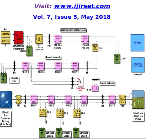
Fig. 4: Smartgrid model with DG sources in MATLAB / Simulink with SDFT based PMU for locating fault in distribution system. [ 19]
VI.SIMULATIONRESULTS
The system described in the foregoing was simulated in healthy fault-free condition with DG sources and then with different faults in the distribution system at different distances. The waveforms observed with a severe fault like a three-phase short circuit for three-phase voltage, current and power are shown in Fig.5 to Fig. 10.
Fig. 5: 3-Φ sending end voltage in primary distribution circuit (V) at 22.9 kV bus BS with a LLL fault at 0.75 sec.
Fig. 6: 3-Φ sending end current in primary distribution circuit (A) at 22.9 kV bus BS with a LLL fault at 0.75 sec.
0 0.1 0.2 0.3 0.4 0.5 0.6 0.7 0.8 0.9 1
-3 -2 -1 0 1 2 3x 10⁴
Time (se c)
S
e
n
d
in
g
e
n
d
v
o
lt
a
g
e
(
V
)
Voltage at sending end bus with a LLL fault at 0.75 sec.
0 0.1 0.2 0.3 0.4 0.5 0.6 0.7 0.8 0.9 1
-6000 -4000 -2000 0 2000 4000 6000
Time (sec)
S
e
nd
in
g
e
n
d c
u
rr
e
n
t
(A
)
Fig. 7: 3-Φ sending end active power in primary distribution circuit (MW) at 22.9 kV bus BS with a LLL fault at 0.75
sec.
The figure 5 -7 shows the sending end voltage, current & active power. When the fault will appear at 0.75 Sec. The system voltage drastically reduces & sending end current will increase because of decrease in system impedance. That will result in sudden change in the active power in system. A fault will produces oscillation in the system which can be easily observed from the waveform.
Fig. 8: 3-Φ receiving end voltage in primary distribution circuit (V) at 22.9 kV bus BR with a LLL fault at 0.75 sec.
Fig. 9: 3-Φ receiving end current in primary distribution circuit (A) at 22.9 kV bus BR with a LLL fault at 0.75 sec.
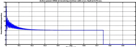
Fig. 10: 3-Φ receiving end power in primary distribution circuit (MW) at 22.9 kV bus BR with a LLL fault at 0.75 sec.
The figure 8 -10 shows the receiving end voltage, current & active power. When the fault will appear at 0.75 Sec. The receiving end voltage and current is nearly equal to zero as the fault will provide low impedance path for the flow of current. The active power in system at receiving end is nearly zero.
0 0.1 0.2 0.3 0.4 0.5 0.6 0.7 0.8 0.9 1
-40 -20 0 20 40 60 80 100
Tim e (sec)
P o w er (M W ) a t s end in g e nd b u s.
0 0.1 0.2 0.3 0.4 0.5 0.6 0.7 0.8 0.9 1
-3 -2 -1 0 1 2 3x 10
4
Time (se c)
R e c e iv in g e n d v o lt a g e ( V )
Voltage at re ce iving end bus w ith a LLL fault at 0.75 se c.
0 0.1 0.2 0.3 0.4 0.5 0.6 0.7 0.8 0.9 1
-400 -300 -200 -100 0 100 200 300 400
Time (se c)
R e c e iv in g e n d c u rr e n t (A )
Curre nt at re ceiv ing e nd bus w ith a LLL fault at 0.75 sec.
0 0.1 0.2 0.3 0.4 0.5 0.6 0.7 0.8 0.9 1
0 2 4 6 8 10 12 14 16 18
Time (se c)
P o w e r (M W ) a t re c e iv in g e n d b u s .
With Smart Discrete Fourier Transform (SDFT) we get voltage and current phasors. For line-to-ground fault
the fault resistance of 0.001 Ω is assume for every 10 kms length on the line. The proposed method is applied to each
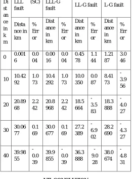
case. Table 1 shows the results of simulation with estimation error defined as given in Eq. 36 for symmentrical & unsymmentrical fault like Three phase fault (LLL), Three phase to ground (LLLG), Double line to ground (LLG) and Line to ground fault (LG) at different distances. It can be found that the errors range from -9.0280 to 2.2421% and minimum error is - 0.0392 % which is nearly zero, which means the suggested method is quite helpful in fault location problem. Actually, error due to DC offsets is present in finding the phasors of voltage and current.
Table 1: Located distance for different faults at various locations and % location error.
Di st an ce in k m
LLL (SC) fault
LLL-G
fault LL-G fault L-G fault
Dista nce in km % Err or Dist ance in km % Err or Dist ance in km % Err or Dist ance in km % Err or
0 0.001 6 0.0 04 0.00 16 0.0 04 0.45 78 1.1 44 1.21 87 3.0 46
10 10.42 92 1.0 73 10.4 292 1.0 73 10.0 350 0.0 87 8.41 73 -3.9 56
20 20.89 68 2.2 42 20.8 968 2.2 42 18.5 664 -3.5 83 18.3 888 -4.0 27
30 30.06 77 0.1 69 30.0 677 0.1 69 27.2 389 -6.9 02 28.2 690 -4.3 27
40 39.98 55 -0.0 39 39.9 855 -0.0 39 36.3 888 -9.0 28 38.0 674 -4.8 31 VII.CONCLUSION
this method. It has been observed during simualtion results that the more than 90% fault can be located accurately. This technique will be an highly efficient & effective, adaptive, and inexpensive fault location technique.
REFERENCES
[1] IEEE Standard IEEE Std C37.114™-2014 (Revision of IEEE Std C37.114-2004), “IEEE Guide for Determining Fault Location on AC Transmission and Distribution Lines.”
[2] Joe-Air Jiang, Jun-Zhe Yang, Ying-Hong Lin, Chih-Wen Liu, and Jih-Chen Ma,“An Adaptive PMU Based Fault Detection/Location Technique for Transmission Lines Part I: Theory and Algorithms”,IEEETransactions on Power Delivery,vol. 15,no. 2,pp. 486–493, Apr 2000.
[3] Trupti P. Hinge, Sanjay S. Dambhare, “New Ground Fault location Algorithm for Transmission Line using Synchrophasors”,Development in Power System Protection 2016 (DPSC), 13th International Conference, IET, Edinburgh, UK, Mar 2016.
[4] Joe-Air Jiang Ying-Hong Lin Chih-Wen Liu Jun-Zhe Yang Tong-Ming Too, “AnAdaptive Fault Locator System For Transmission Lines”,Department of Electrical Engineering,National Taiwan University, Taipei, Taiwan, pp. 930–936,1999.
[5] Z. M. Radojević, C. H. Kim, M. Popov, G. Preston, V. Terzija,“New Approach for Fault Location on Transmission Lines Not Requiring Line Parameters”,International Conference on Power Systems Transients (IPST2009), Kyoto, Japan, Jun 2009.
[6] Chih-Wen Liu, Tzu-Chiao Lin, Chi-Shan Yu, and Jun-Zhe Yang, “A Fault Location Technique for Two-Terminal Multi-section Compound Transmission Lines Using Synchronized Phasor Measurements”,IEEETransactionson S m a r t G r i d,vol. 3, issue 1, Mar 2012.
[7] Chetan Patil and Harpreet Singh,“Synchrophasor Measurement Method For Analysis of Fault Location Technique on Transmission Lines”,
International Journal of Engineering, Education and Technology (ARDIJEET),ISSN 2320-883X,vol. 03, issue 02 , pp. 1–11,Jan2015.
[8] Joe-Air Jiang, Jun-Zhe Yang, Ying-Hong Lin, Chih-Wen Liu, and Jih-Chen Ma,“An Adaptive PMU Based Fault Detection/Location Technique for Transmission Lines—Part II: PMU Implementation and Performance Evaluation”,IEEETransactions on Power Delivery,vol. 15,no. 4,pp. 1136–1146, Oct 2000.
[9] Seung-Jae Lee, Myeon-Song Choi, Sang-Hee Kang, Bo-Gun Jin, Duck-Su Lee, Bok-Shin Ahn, Nam-Seon Yoon, Ho-Yong Kim, and Sang-Bong Wee, “An Intelligent and Efficient Fault Location and Diagnosis Scheme for Radial Distribution Systems”, IEEETransactions on Power Delivery,vol. 19,no. 2,pp. 524–532, Apr 2004.
[10] Tamer Kawady and Jürgen Stenzel, “A Practical Fault Location Approach for Double Circuit Transmission Lines Using Single End Data”,
IEEE Transactions on Power Delivery, Vol. 18, No. 4, pp. 1166-1173, Oct 2003.
[11] Myeon-Song Choi, Seung-Jae Lee, Duck-Su Lee, and Bo-Gun Jin, “A New Fault Location Algorithm Using Direct Circuit Analysis for Distribution Systems”, IEEE Transactions on Power Delivery, vol. 19, no. 1, pp. 35-41, Jan 2014.
[12] Adly A. Girgis, Christopher M. Fallon, and David L. Lubkeman,, “A Fault Location Technique for Rural Distribution Feeders”, IEEE Transactions on Industry Application, Vol. 29, No. 6, pp. 35-41, Nov/Dec 1993.
[13] James A. Momoh, “Smart Grid Design for Efficient and Flexible Power Networks Operation and Control”, Power Systems Conference and Exposition, PSCE-2009, IEEE/PES, Mar 2009.
[14] Richard E. Brown, “Impact of Smart Grid on Distribution System Design”, Power and Energy Society General Meeting – Conversion and Delivery of Electrical Energy in the 21st Century, Jul 2008.
[15] Wang, Luxin and Hyun, Seung Ho, “A New Fault Location Method for Distribution System under Smart Grid Environment”, The 6th
International Forum on Strategic Technology, pp. 469-472, Aug 2011.
[16] Jun-Zhe Yang and Chih-Wen Liu, “A Precise Calculation of Power System Frequency”, IEEE Transactions on Power Delivery, Vol. 16, No. 3, pp. 361-366, Jul 2001.
[17] Pradip Kumar Sadhu, Soumen Dhara, Alok Kumar Shrivastav and Debabrata Roy, “Superconducting Fault Current Limiters for Micro Grid Application”, International Journal of Mechatronics, Electrical and Computer Technology (IJMEC), vol. 5(16), pp. 2246-2257, Jul 2015.
[18] Lei Chen and Yi Tang, “Optimal Allocation of Flux-Coupling-Type SFCLs for a Micro-Grid with Wind-PV Hybrid Generation and Battery Energy Storage”, Asian Conference on Energy, Power and Transportation Electrification (ACEPT 2016), Oct 2016.
[19] Umer A. Khan, J. K. Seong, S. H. Lee, S. H. Lim, and B. W. Lee, “Feasibility Analysis of the Positioning of Superconducting Fault Current Limiters for the Smart Grid Application Using Simulink and SimPowerSystem”, IEEE Transactions on Applied Superconductivity, Vol. 21, No. 3, pp. 2165-2169, Jun 2011.
[20] Geoff Walker, “EvaluatingMPPT converter topologies using a MATLAB PV model,” J. Electr. Electron. Eng. Aust., vol. 21, no. 1, pp. 49–56, 2001.
[21] Hiren Patel and Vivek Agarwal, “PV Based Distributed Generation with Compensation Feature Under Unbalanced and Non-linear Load Conditions for a 3-4, 4 Wire System”, IEEE International Conference on Industrial Technology (ICIT- 2006), pp. 322-327, Dec 2006.
[22] Hiren Patel and Vivek Agarwal, “MATLAB-Based Modeling to Study the Effects of Partial Shading on PV Array Characteristics”, IEEE Transactions on Energy Conversion, Vol. 23, No. 1, pp. 302-310, Mar 2008.
[23] Hiren Patel and Vivek Agarwal, “Maximum Power Point Tracking Scheme for PV Systems Operating Under Partially Shaded Conditions”,
IEEE Transactions on Industrial Electronics”, Vol. 55, No. 4, pp. 1689-1698, Apr 2008.
[25] Javad Sadeh, Ehsan Bakhshizadeh, Rasoul Kazemzadeh, “A New Fault Location Algorithm for Radial Distribution Systems using Nodal Analysis”, Electrical Power and Energy Systems, 45, pp. 271–278, 2013.
[26] Marcel Istrate, Mircea Guşă and Ştefan Ţîbuliac, “Assessment of Fault Location Algorithms in Transmission Grids”, IEEE Bucharest Power Tech Conference, Romania, pp. 1-6, Jul 2009.
[27] Po-Chen Chen, Vuk Malbasa and Mladen Kezunovic, “Locating Sub-Cycle Faults in Distribution Network Applying Half-Cycle DFT Method”, T&D Conference and Exposition, Chicago, USA, IEEE PES, Jul 2014.
[28] Cecília Alves Buriti da Costa, Núbia Silva Dantas Brito and Benemar Alencar de Souza, “Real-Time Evaluation of Impedance-Based Fault Location Algorithms”, 12th International Conference on Industry Applications (INDUSCON), Curitiba, Brazil, Nov 2016.
[29] P. Suresh Babu and Dr. S. V. Jayaram Kumar, “A Smart Discrete Fourier Transform Algorithm Based Digital Multifunction Relay for Power System Protection”, International Journal of Computer and Electrical Engineering, vol.3, no.1, pp. 66-73, Feb 2011.
[30] K. Ravishankar and D. Thukaram, “Estimation of Fault Location on UHV Transmission Line using Synchronized PMU Measurements”, 16th National Power Systems Conference, pp. 722-727, Dec 2010.
[31] Ratan Das, Murari Mohan Saha, Pekka Verho and Damir Novosel, “Fault Location Techniques for Distribution Systems”, 17th International Conference on Electricity Distribution, Barcelona, pp. 1-6, May 2003.
[32] Cansın Y. Evrenoso˜glu and Ali Abur, “Fault Location in Distribution Systems with Distributed Generation”, 15th PSCC, Liege, pp. 1-5, Aug
2005.
![Fig. 1. Smart Grid Intelligent automation functions [13].](https://thumb-us.123doks.com/thumbv2/123dok_us/1571996.1193315/2.595.195.407.439.589/fig-smart-grid-intelligent-automation-functions.webp)
![Fig. 2. Configuration of adaptive PMU based fault location system [2,4].](https://thumb-us.123doks.com/thumbv2/123dok_us/1571996.1193315/7.595.194.401.175.386/fig-configuration-adaptive-pmu-based-fault-location.webp)