Survey on Automatic Welding System
Shriya Khedekar1, Sampada Lokhande2, Akash Pasari3, Sunita Kulkarni4,
B.E. Student, Dept. of E&TC, M.I.T. College of Engineering, Pune, Maharashtra, India1 B.E. Student, Dept. of E&TC, M.I.T. College of Engineering, Pune, Maharashtra, India2 B.E. Student, Dept. of E&TC, M.I.T. College of Engineering, Pune, Maharashtra, India3 Assistant Professor, Dept. of E&TC, M.I.T. College of Engineering, Pune, Maharashtra, India4
ABSTRACT:Automation plays powerful role in many fields. Automation in welding has grabbed significant role in
industries since last few years. This paper introduces various methods used to automate the welding process used in industries. The methods may be generalized or specific for a job depending on the requirements. The cost factor also plays a major role i.e. it will vary according to the degree of automation used in the process. A fully or generalized automatic welding process will be much more expensive than a process which welds a specific job. Thus, this paper reviews description of different algorithms for automated welding process.
KEYWORDS:Automatic welding, Seam Tracking, PLC, Robotic Arm, Arduino.
I. INTRODUCTION
Welding is a process of joining two metals in the presence of suitable amount of heat with or without application of pressure. Welding is responsible for permanent joints. Conventionally, there was manual process of welding in industries but with time in order to increase productivity, accuracy, safety and many more parameters automation was introduced and has been increasing since. Human welders have been replaced by robot welders as it gives maximum throughput as well as they have a greater accuracy. But automation in industries is expensive thus, only large scale industries are able to implement it in their plants but now-a-days it is possible to build an automated welding system of low cost by using various strategies. Various algorithms have been developed to automate process of welding in order to achieve maximum advantages.
II. SEAMTRACKINGINAUTOMATICWELDINGSYSTEM
A. Machine Vision System
Interpretation of an image of scene or an object through use of optical non contact sensing mechanics for the purpose of obtaining information and controlling processes or machines is called as machine vision.
In machine vision system camera and controller plays an important role. Camera is used to capture image of worktable with workpiece on it. After capturing of image in camera controller is used for computing position, dimension and orientation of workpiece. Then controller controls the electrode based on calculations. In this way welding can be done accurately.
Fig. 2.Anatomy of machine vision
In workflow of system first step is to calibrate and initialize camera. Next step is to bring the electrode at initial position. After initialization of system image of scene is captured. Processor processes captured image and then position and length of the weldline is determined. Final step is to actuate the electrode, where controller guides the electrode to move along weld line and then welding is done. After completing welding, electrode is brought back to its initial position. Image processing is one of the important step in the process as controller can make decisions on based of processed image. In image processing captured image is converted into a binary image by selecting a proper threshold value. In this processing weld line is converted into black pixels and all other parts of the image are converted into white pixels.
Fig. 3.Workflow of the system
B. Weld tracking Based on Artificial Vision
In this algorithm welding system based on laser vision technique is explained. The design can run in a low performance computer, and off the self-components (webcam and laser). For the automation of welding processes in heavy industries, a laser-stripe system is presented in this paper.
C. Welding Path Motion Programming
Motion is specified by input image files to simplify interactions between an engineer and a robot when setting up the autonomous operation. Automated code is generated which orders the welding tip to move along the path specified by the input bitmap image which is transmitted via internet by the remote computer vision system.
The process of extracting the information from the binary image mainly takes place using the Algorithm which mainly works on two steps namely tracing and arc approximation.
1.Tracing step: A Binary image of the original coloured image is obtained and the desired contours can be specified using black and white colours which is done by an engineer during the adjustment of the technological chain remotely using the computer vision system, thus which the help of Moore-Neighbour tracing algorithm an array is formed with all the coordinates of the neighbour black points of the input binary image.
2.Arc Approximation step: all the coordinates obtained from above step can be used for point to point welding but if the number of coordinates is large then it causes overloading of the controller also the speed of the welding arm decreases as the robot reconfigures it’s position at each reference level. Thus to overcome this problem arc approximation technique is used, which considers the movement along an arc considering only three points to increase the speed and decrease the code size
III.PLCBASEDAUTOMATICWELDING
A. For Circular weld track
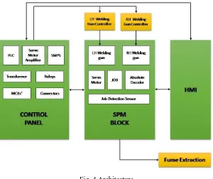
It consists of an algorithm which is used to automate a welding process in which a knuckle bracket is welded on a circular shaft of the shock absorber. The PLC is used as a controller. It basically consists of three main blocks: SPM (Special Purpose Machine) Block, Control Block and HMI (Human Machine Interface) Block.
Fig. 4.Architecture
be set manually using HMI and it can be used for system testing purpose. While in Auto mode, everything is done automatically. The job placed is detected by the job detection sensor, then the PLC controls the guns and they start moving forward. The servo motor starts rotating the job and this rotations are monitored by the encoder and send this information to the controller. When the required angle is reached the process is terminated and the guns move to their initial position.[4]
B. For Linear Track
The process of welding the bus body frame is automated in order to increase the production as well as reduce the safety issue. The robot mostly takes a linear path for welding by using PLC and FANUC program. Also, the strength of the weld produced by this method is more than that achieved by manual arc welding process. MIG welding is used to achieve so. The robot is placed near the bus body frame and the servo motor isprogrammed such that the weld-gun moves along the weld path. As the motion required is linear, the rotary motion of the servo is converted into linear using a rack and pinion setup. The welding gun along with feed wire unit inside it is placed at a distance of 1.5mm away from the frame. A pneumatic pump is used to push forth and back the welding gun from the frame.[5]
Advantages:
1. Increased production.
2. Less time consumption.
3. Better safety.
4. Improved and consistent quality 5. Increased productivity
6. Reduction in consumables
7. Less man power is requires
Disadvantages:
1. Complexity is high.
2. Can be used only for specific job Designs.
IV.MULTIPURPOSEROBOTICARM
This topic includes design and construction of a robotic arm similar to a human arm which can be used for various purposes such welding, gripping spinning, etc. The Arduino Uno R3 is the controller used to control the motion of the arm. Servo motor and stepper motor along with L298D driver is used to rotate the arm. A sonar sensor SR04 is used to detect the position of the object to be operated. [6]
The algorithm is as follows: I. Scan the position II. Get the position
III. React according to the position IV. Take to the destination V. Return to the initial position
Advantages:
1. Servo is used for functioning and hence the arm can be rotated from 0° to 180°.By coding the arm can be rotated with any angle between 0° to 180°.
Disadvantages:
V. CONCLUSION
This paper represents different approaches for automation in welding. Some algorithms presented above are capable of performing welding on any type of a job and some of them are for specific job. Systems which are designed for generalized welding has complex algorithm as it has to take into account all the parameters such as dimension, position and orientation etc. Large investments are required to build such systems. To build system for specific job we don’t require such complex algorithm and such systems are inexpensive as compared to generalized robot welder. Digital image processing plays an important role in automatic welding system, it helps in seam tracking.
REFERENCES
1. Arun Prakash, “Vision Algorithm For Seam Tracking inAutomatic Welding System”, International Journal of Recent advances in Mechanical Engineering (IJMECH) Vol.4, No.1, February 2015.
2. Alberto Fern´andez Vill´an, Rodrigo Garc´ıa Acevedo, Eduardo Alvarez Alvarez, Daniel F. Garc´ıa, Rub´en Usamentiaga Fern´andez, Marco
Jimenez Meana, Jose Manuel Garc´ıaS´anchez, “Low Cost System for Weld Tracking Based on Artificial Vision”, IEEE
978-1-4244-3476-3/09/$25.00, 2009.
3. Oleg I. Borisov*, Vladislav S. Gromov*, Sergey A. Kolyubin*, Anton A. Pyrkin*, Alexey A. Bobtsov*†,Vladimir I. Salikhov*‡, Alexey O. Klyunin* and Igor V. Petranevsky*, “Human-Free Robotic Automation of Industrial Operations*”, 978-1-5090-3474-1/16/$31.00 ©2016 IEEE.
4. Kunal V. Patil, Balaji K. Gadade, Parag G. Raut, Suvarna K. Gaikwad, Ganesh Toke, “A Novel approach of MIG Welding using PLC”, International Journal of Advanced Research in Electrical, Electronics and Instrumentation Engineering, Vol. 3, Issue 2, February 2014. 5. C.Satheesh Kumar, K.Pasupathi, R.Pradeep, S.Pradeep Kumar, M.Sivasankar, “Automatic Welding in Bus Body Frame”, International
Journal of Innovative Research in Science,Engineering and Technology, Vol. 6, Issue 3, March 2017.