a
Corresponding author: [email protected]
Comparison of Flow Structures in the Downstream Region of a Cylinder
with Flexible Strip
Süleyman TEKN1,a , Sedat YAYLA1
1Department of Mechanical Engineering, Yuzuncu Yil University, 65080 Van, Turkey
Abstract. The present study investigates the details of flow structure to downstream of a circular cylinder mounted on a flat surface, in successive plan-view plane both in the boundary layer and up level region. The behavior of the flow in the wake of the bare cylinder and attached a flexible strip which has a 1400 N/mm2 modulus of elasticity vinyl PVC transperent film. The length of strip 240 mm (L/D=4) is investigated using Particle Image Velocimetry (PIV) technique for Reynolds numbers based on the cylinder diameter of 2500. The flow data downstream of the cylinder are presented using time-averaged velocity vector map, Vavg, streamline patterns, avg, vorticity contours, avg, and
Reynolds stress correlations, u’u’avg, v’v’avg, u’v’avg and rms velocity values. The locations of the peak values of
Reynolds stress correlations and other data are also presented in both bare cylinder and attached body in order to determine the regions under high fluctuations. Another L/D ratios will be investigated in other experiments.
1 Introduction
The flow around and in the wake of bluff bodies has been a subject of interest to scientists, engineers, and designers for many years due to its convenient importance. Formation and shedding of vortices from a cylinder have fundamental research values in the areas of vortex dynamics and bluff body flows as Lam and Dai (2002) [1] stated. Mi and Antonia (1999) [2] performed wind tunnel tests to obtain Reynolds stress and vorticity data in the cylinder wake.
The appearance of vortex shedding is accompanied by a large fluctuation of drag and lift forces, which may cause structural vibrations and acoustic noises, and shorten the life of the solid structure, as stated by Chen and Aubry (2005) [3]. Therefore, control of wakes of bluff bodies is of paramount importance in lots of engineering applications, such as in aircraft and automobile industry. Sahin et al. (2005) [4] reported that variations of Reynolds numbers affect the size of wake flow region, location of singular points, position of the peak values of turbulence quantities substantially.
In an effort to study a passive control device, Strykowski and Sreenivasan [5] have showed that the vortex shedding past a circular cylinder can be controlled over a limited range by the proper placement of a (smaller) control cylinder close to the main cylinder. They have conducted a quite exhaustive investigation, using laboratory experiments to study the effect of the size and position of the control cylinder on the behavior of the vortex shedding from the main cylinder. They found that there exists a domain close to the main cylinder where the placement of a control cylinder can
completely suppress the vortex shedding. Akilli et al. [6] conducted experiments with splitter plates to a cylinder having different length attached behind the cylinder base with a gap ratio G/D. Experiment reported that Reynolds stress has a peak value approximately 8.5 times smaller than the concentrations occurring for a bare cylinder.
Cimbala and Garg [8] investigated the effect of the attached splitter plate on the flow characteristics downstream of a fixed cylinder and a freely rotating cylinder. The effect of fixed cylinder with an attached plate was similar to the case of a freely rotating cylinder, the flow field with plate of L/D > 2. However, when L/ D < 2, the flow field was similar to the case without the splitter plate.
The study of Cardell [9] showed that the introduction of low solidity splitter plates did not change the basic near wake structure and that sufficiently high solidity uncoupled the large scale wake instability from the body with the primary vortex formation occurring downstream of the separation bubble due to instability of the wake profile.
Zdravkovich (1977, 1982, 1987) provided an overviewof loading characteristics and flow patterns. Zdravkovic and Pridden (1977) emphasized the discontinuous jump in base pressure at a critical spacing of the cylinders L/D=3.5, in which L is the distance between centers of the cylinders and D is the cylinder diameter. Classifications of the qualitative flow regimes of the tandem cylinder arrangement are provided by Igarashi (1981) [10], (1984) [11] and Zdravkovich (1982) [12]. In substance, below a threshold value of L=D, referred to in the literature as the critical spacing, no vortex shedding occurs in the gap region between the C
Owned by the authors, published by EDP Sciences, 2015
cylinders, whereas above it, vortex shedding occurs from both cylinders. This threshold appears to be a function of Reynolds number.
Apelt and West (1975) [13] conducted a series of experiments to investigate the effect of the splitter plate on the flow characteristics by measuring the pressure distribution, the vortex shedding frequency and the flow visualizations. It was found that the splitter plates were able to remarkably reduce the drag force, to increase the base pressure, to narrow the wake width and to change the Strouhal number.
2 Experimental set up and
instrumentation
Experiments were conducted on a circulating free-surface water channel. The internal dimensions of the water
channel were of 8000 mm × 1000 mm × 750 mm which was made from 15 mm thick transparent Plexiglas sheet with upstream and downstream fiberglass reservoirs. Before reaching the test chamber, the water was pumped into a settling chamber and passed through a honeycomb section and a 2:1 channel contraction.
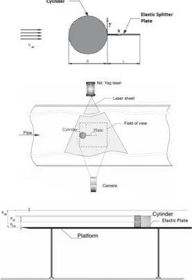
The schematic drawing of experimental arrangement is presented in figure 1. The depth of the water in the test section was 600 mm (hw) for the present experiments. The Reynolds number based on the cylinder diameter was kept constant for experiment as Re=2500 which corresponds to the free-stream velocity of 41 mm/s. Two different images were captured at two distinct location at 5 mm below the top (hu ) and 250 mm (hm) above the bottom surface of platform. Figure 1 shows the schematic drawing of the experimental experimental set-up and definition of the parameters.
Figure 1. Schematic of the experimental system of set-up and definition of the parameters: cylinder diameter D, length of elastic plate
L, laser sheet height hL and free-stream velocity U.
Instantaneous velocity vectors were measured in a region illuminated by a two-dimensional laser sheet by using the Stereo PIV technique which allows performing three dimensional measurements on two dimensional
eyesight. The two views are then combined using one of an assortment of algorithms to reconstruct the three-dimensional field. The detailed information about Stereoscopic PIV could be obtained from Adrian [7].
Velocity vector measurements were performed by a Dantec stereoscopic PIV system. The flow field illumination was provided by two Nd:Yag pulsed laser sources of a wave length of 532 nm, each with a maximum energy output of 120 mJ. Dantec Flow Map Processor which controlled the timing of the data acquisition was used for synchronizing the camera and laser units. The movements of the particles were recorded using a CCD camera with a resolution of 1600 x 1186 pixels. The camera was equipped with a 60 mm focal-length lens. Totally 350 instantaneous images were taken with an acquisition frequency of 15 Hz for each continuous run. Dantec digital PIV software employing frame-to-frame adaptive correlation technique was used to calculate the raw displacement vector field from instantaneous images of measuring field. In the image processing, 32 x 32 pixels with rectangular effective interrogation windows were used. During the interrogation process, an overlap of 50% was employed. Totally 7227 (99x73) velocity vectors were acquired (at a rate of 15 frames per second) for an instantaneous velocity field.
The diameter and height of cylinder were 60 mm and 500 mm respectively.Length of the elastic splitter plate was selected to be 240 mm. The free stream velocity, U was 0.41 m/s, corresponding to Reynolds number of 2500 based on cylinder diameter.Laser sheets were oriented parallel to the bottom surface of the water channel at 250 mm height from bottom surface for mid-level images and 5 mm below top level of cylinder for up-level images. The depth of water above the platform was maintained at 600 mm as a constant value which implies uniform flow formation in the channel owing to no variation in the flow depth and thus the average flow velocity. The Froude number, which is defined as Fr= U2/ghw, based on the water depth was 0.029.
3 Result and discussion
Comparison of the normalized flow patterns of the bare cylinder and the attached body, velocity vectors Vavg,
time-averaged streamline patterns avg, streamwise
Reynolds normal stress u’u’/U2avg, transverse Reynolds
normal stress v’v’/U2avg, Reynolds stress correlations
u’v’/U2avg, contours of vorticity avg, root mean square
streamwise velocity urms, root mean square transverse velocity vrms, turbulent kinetik energy, are displayed in figures 2-8. For these and other figures, the minimum and normalized incremental values of the patterns are given on each images.
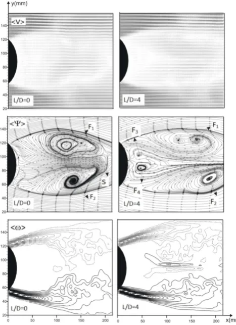
A well-defined wake region is evident from velocity vector fields, in first row, corresponding streamline topologies, in the second row, and vorticity, in last row, are shown in figure 3. Time-averaged streamline topology is interpereted in terms of foci, F, and saddle point, S. Comparison of the time-averaged patterns shows that flow structures of the wake are almost equally
symmetrical with respect to centerlines of the two models. Patterns of time-averaged streamline topology avg identify the major changes of the nearwake
downstream of the cylinder. They exhibit clearly seen critical points, foci, F1 and F2 and saddle points S. Streamline topology of instantaneous images shown in the mid-row of figures 2-3 shows at least two critical points, the focus of which corresponds to vortex centers, located both side of the splitter plate. The saddle point indicated by the time-averaged streamline topology is developed for the attached cylinder approximately X/D=3.3 for boundary level. By attaching flexible splitter plate wake flow region was narrowed with respect to bare cylinder case for midplane elevation. It can be seen on streamline topology that shows Foci points forms farther. For vorticity contours minimum and incremental values are ±0.5 and 0.5 respectively. Maximum vorticity values are almost same for all cases. Although Reynold stress corrolations and values of turbulent kinetic energy were decreased by attaching elastic splitter plate, vorticity countours approach to cylinder base for mid-height level.
Figure 3. Time-averaged velocity vector field Vavg, and streamline topology avg, vorticity contours avg (minimum and incremental values are ±0.5 s-1 and 0.5 s-1 for vorticity respectively) for boundary layer elevation.
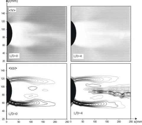
Figures 4-5 showthe contours of the normalized TKE for the two models at Re = 2500. When the flow structures of the cylinder are compared to those of the atteached cylinder for two different images, both cylinders have two maxima of TKE. A high rate of entrainment between the free-stream and the wake flow regions is developed, and hence the two peak values of the TKE occur on both side of the cylinder symmetry plane. Minimum and incremental values are ±0.005 and 0.01 respectively. The peak value of the TKE for the bare cylinder has a value of 0.21 and that for attached cylinder is 0.145 for boundary level at L/D=4. On the other hand, while maximum TKE values are 0.19 and 0.1 for bare cylinder and attached body for up section.
Figure 4. Turbulent kinetic energy for up-level. Minimum and incremental values are 0.005 and 0.01 respectively.
Figure 5. Turbulent kinetic energy for mid-level. Minimum and incremental values are 0.005 and 0.01 respectively.
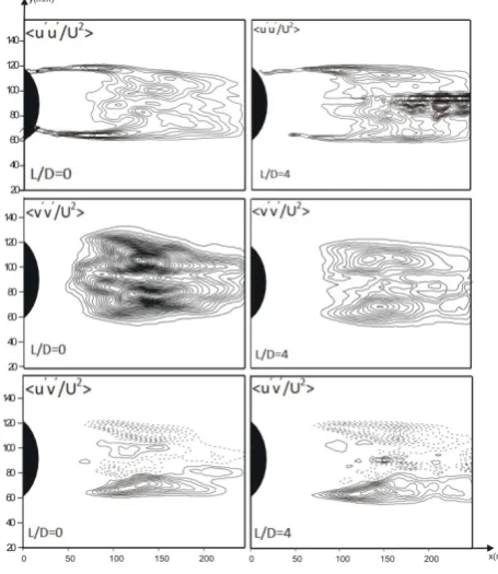
The vortex formation length in the wake region for boundary layerof the two models can also be described by means of the point of maximum values of streamwise Reynolds normal stress u’u’/U2avg, transverse Reynolds
normal stress v’v’/U2avg, and Reynolds shear stress
correlations u’v’/U2avg. Here, the solid and dashed lines
show the positive (anticlockwise) and negative (clockwise) spanwise vorticity layers, respectively. Reynolds stress correlations depict a set of extrema on either side of the wake centerline for the bare cylinder and attached shape in figures 5-6. For streamwise and transverse Reynold normal stress, minimum and incremental values are ±0.01 and 0.005 respectively.
Reynold shear stress’s minimum value is ±0.003 and increments are 0.003. The maximum values of the streamwise Reynolds normal stress with double peaks for the two models occur at locations of approximately 2.4D and 3.5Da with values of 0.21 and 0.145 respectively
Figure 6. Time-averaged streamwise Reynold normal stress, transverse Reynold normal stress (minimum and incremental values are ±0.01 and 0.005), for Reynold shear stress minimum and incremental values are ±0.003 and 0.003 contours for mid-level investigation.
Figure 7. Time-averaged streamwise Reynold normal stress, transverse Reynold normal stress (minimum and incremental values are ±0.01 and 0.005), for Reynold shear stress minimum and incremental values are ±0.003 and 0.003 contours for up-level investigation.
In figures 8-9, the turbulent flow characteristics in the flow passage of the cylinders are also presented in terms of root mean square values of streamwise velocity, u, urms/Uavg and transverse velocity, v, vrms/Uavg components.
First column represents the bare and second column in case of L/D=4. Root mean square of streamwise urms and transverse velocity components vrms normalized by free stream velocity U∞ at various elevations are presented.
Minimum and incremental values are 0.02 and 0.02 for all urms/Uavg and vrms/Uavg. Maximum value of urms/Uavg and vrms/Uavg is 0.46 and 0.44 for bare cylinder
while decreased to 0.40 and 0.30 respectively for attached cylinder for the case of mid-height. As the flow goes downstream, urms/Uavg and vrms/Uavg values were decreased nearly %30 and %25 for up-height level.
Figure 8. Time-averaged urms and vrms minimum and
incremental values are ±0.02 and 0.02 respectively for mid-level.
Figure 9. Time-averaged urms and vrms minimum and
incremental values are ±0.02 and 0.02 respectively for up-level.
4 Conclusion
for the up-level which is 5 mm under the top of the cylinder. The decrease in the peak concentration for the L/D=4 case as compared to the no-plate case indicates that the presence of a flexible splitter plate is effective in decreasing the peak value of the Reynolds shear/normal stress, turbulent kinetic energy root mean square of streamwise and transverse velocity component. However, for mid-height examination, level of stresses are decreased vorticity courtours were come close to cylinder base and maximum values approximately could not be altered.
Nomenclature
D cylinder diameter
Daattached cylinder
L Lenght of strip
F center of focus
Re Reynolds number
S saddle point
u streamwise velocity component
v transverse velocity component
U∞free stream velocity
S saddle point
avg, < > average mean
u’v’Reynolds stress
u’fluctuations of u v’mean fluctuations of v urmsroot mean square of u
vrmsroot mean square of v
streamline vorticity
V velocity vector
hu up-height of laser sheet
hm mid-height of laser
sheet
hw height of the water
References
1. K.M. Lam, G.Q. Dai, Exp. Thermal and Fluid Science, 26, 901-915 (2002)
2. J. Mi, R.A. Antonia, Int. Comn. Heat Mass Transfer,
26(1), 45-53. (1999)
3. Z. Chen, N. Aubry, Nonlinear Science and
Numerical Simulation, 10, 205-216 (2005)
4. B. Sahin, A. Akkoca, N.A. Ozturk, H. Akilli, Investigations of flow characteristics in a plate fin and tube heat exchanger model composed of single cylinder. Acepted forpublication in Int. J. Heat and Fluid Flow (2005)
5. P. Strykowski, K. Sreenivasan, Journal of Fluid Mechanics 218, 71-107 (1990)
6. H. Akilli, B. Sahin, N.F. Tumen, Suppression of vortex shedding of circular cylinder in shallow water by asplitter plate. Flow Measurement and Instrumentation16 211–219 (2005)
7. R.J. Adrian, “Twenty Years of Particle Image Velocimetry”, Experimental Fluids, Vol. 39, pp. 159–169, (2005)
8. J.M. Cimbala, S. Garg, AIAA J. 29 1001–1003 (1991)
9. G.S. Cardell, Flow past a circular cylinder with a permeable wake splitter plate, Ph.D. Thesis, California Institute of Technology, (1993)
10. T. Igarashi, Bulletin of JSME 24, 323–331 (1981) 11. T. Igarashi, Bulletin of JSME 27, 2380–2387 (1984) 12. M.M. Zdravkovich, Flowinduced oscillations of two
interfering circular cylinders. In Proceedings International Conference on Flow Induced Vibration, pp. 141–154. Bowness-on-Windermere, England, Cranfield, UK: BHRS (1982)
13. C.J. Apelt, G.S. West, Journal of Fluid Mechanics
71, 145–160. (1975)
14. S. Yayla. Journal of Mechanical Engineering, Vol.