ISSN 2348 – 7968
ANALYSIS AND STRUCTURAL OPTIMIZATION OF
5 TON H-FRAME HYDRAULIC PRESS
Santoshkumar S. Malipatil1, Prof. Yogita N. Potdar2, Prof. A. C. Mattikalli3
1
Department of Mechanical Engineering, M.M.Engineering College, Visvesvaraya Technological University, Belgaum, Karnataka, India
2
Department of Mechanical Engineering, M.M.Engineering College, Visvesvaraya Technological University, Belgaum, Karnataka, India
3
Department of Mechanical Engineering, M.M.Engineering College, Visvesvaraya Technological University, Belgaum, Karnataka, India
Abstract
Using the optimum resources possible in designing the hydraulic presses frame can effect reduction in the cost of the hydraulic presses. By optimizing the weight of material utilized for building the structure. An attempt has been made in this direction to reduce the volume of material. So here we consider an industrial application project consisting of mass minimization of H-frame type hydraulic press. This press has to compensate the forces acting on the working plates and has to fulfill certain critical constraints. ANSYS has been used for this analysis the main aim is to reduce the cost of the Hydraulic presses without compromising on the quality of the output. With regarding to design specification, stress distribution, deflection, and cost, are focused on optimized design. The methodology followed in this work is comparison of stresses induced in machine for different thickness used for construction of frame and column of the H-frame type hydraulic press.
.
Keywords: Hydraulic press, Quality, Optimization, plates, design specification.
1. Introduction
A hydraulic press is a machine using a hydraulic cylinder to generate a compressive force. Frames and column and cylinder are the main components of the hydraulic press. In this project H type hydraulic press frame and column are designed by the design procedure. Press frame and column are analysed to improve its performance and quality for press working operation. Structural analysis has become an integral part of the product design.
Structural analysis has been applied on H frame hydraulic press structure by using analysing software ANSYS. An integrated approach has been developed to verify the structural performance and stress strain distributions are plotted by using ANSYS software. According to the structural values the dimensions of the frame and
column are modified to perform the functions satisfactory. Hydraulic presses derive the energy they
deliver through hydraulic pressure. The hydraulic press depends on Pascal's principle, the pressure throughout a closed system is constant. At one end of the system is a piston with a small cross-sectional area driven by a lever to increase the force. Small-diameter tubing leads to the other end of the system.
2. H-frame hydraulic press
ISSN 2348 – 7968 Fig. 1 H-frame hydraulic 5ton press
2.1 Components of the H-frame hydraulic press
a) Top frame b) Moving frame c) Column d) Press pin e) Bottom support f) Working table
g) Cylinder mounting table.
2.2 Problem statement
Analyzing the existing 5 ton hydraulic press finding the maximum stress induced in the model during the working condition. Then by calculating its factor of safety if it’s more than 3 then we will try to keep it in 2.5 to 3 so that its weight reduces and finding the maximum stress and deflection in the optimized design, without compromising on quality of output.
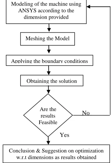
2.3 Flow chart to indicate stage of the methodology
No
Yes
1st Stage: According to the dimensions of the H-frame hydraulic press for before optimization have been used to model in ANSYS.
2nd Stage: Applied constraints and maximum load to find
the maximum stress induced in the hydraulic press 3rd Stage: Structural analysis done.
4th Stage: The results obtained from the analysis are interpreted & checked for their validity and material optimization is carried out.
3. Specifications of Material used
i. Material used for manufacturing the machine: Mild steel
ii. Carbon content in the mild steel: 0.40 % of carbon
iii. Density : 7801Kg/m3
iv. Ultimate tensile strength of the mild steel:650 N/mm2
v. Young’s modulus:2X10⁵ N/mm2 vi. Poisson’s ratio:0.30
3.1 H-frame hydraulic press before optimization
Fig. 2 Front view of H-frame hydraulic press.
Fig. 3 Top view of H-frame hydraulic press.
3.2 Optimization of Press Machine components
Meshing the Model
Applying the boundary conditions
Obtaining the solution
Are the results Feasible
Conclusion & Suggestion on optimization w.r.t dimensions as results obtained Modeling of the machine using
ISSN 2348 – 7968 The idea for optimizing a structure is to modify the sizes of
structural members, i.e., use size parameters (plate thicknesses, bar cross-sectional areas, etc.) as design variables in the optimization process. This approach is called the sizing optimization method. A realistic need in designing structures, e.g., Top plate, Movable plate, Column and Bottom plate and rib is to find an optimal design for minimizing weight and deflection , maximizing safety, minimizing the cost of products.
3.3 Results for before optimization
Maximum stress distribution obtained at working plates before optimized dimensions is 51.197 MPa.
Fig 4: Stress distribution under static loading condition
3.4 Results Obtained by ansys for before
optimization
The Results obtained from the analysis
• The Maximum stress induced in the machine frame 51.197 MPa
• The Maximum Displacement for this load = 0.03704 mm
• The Maximum stress induced in the machine frame (51.197 MPa) is far below the yield stress of Mild steel is i.e. 250 MPa.
• The factor of safety = (Yield stress / Maximum stress induced in the machine)
• The factor of safety = 250 / 51.197 =4.883.
• Now by analytically the maximum stress induced in press is calculated.
• Therefore the thickness of column will be reduced from (40mm to 12mm), moving & top plate (45mm to 15mm), Rib (45 to 12mm) we go for further analysis
and material optimization.
4. Need for Optimization
Herein where the need for optimization plays a very important role and the best possible solution has to be delivered within the available resources and constraints. Most of the optimization problems are made up of three components:
a) An objective function, which we want to minimize or maximize. For example in this case we are interested in minimizing the weight of material of the press frame.
b) A set of design variables that affect the value of objective function. The variables in our case are: • Geometry of the press.
• Material used • Height of the press. • Loading conditions.
c) A set of constraints. In our case the constraints are:
• Applied Load.
• Daylight span and height.
4.1 Results for after optimization
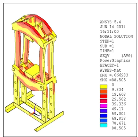
Maximum stress distribution obtained at working plates before optimized dimensions is 88.505 MPa.
Fig 5: Stress distribution for optimized dimensions.
4.2 Results obtained by ansys for after optimization
• The Maximum stress induced in the machine
ISSN 2348 – 7968
• The Maximum Displacement for this load =
0.066983 mm
• The stress obtained now is now slightly below the half of yield stress. Here we got factor of safety minimum 2.82.
• The Maximum stress induced in the machine
frame (88.505 MPa) is far below the yield stress of Mild steel is i.e. 250 MPa.
• The factor of safety = Yield stress / Maximum stress induced in the machine.
The factor of safety = 250 / 88.505=2.824.
Our purpose is to keeping factor of safety between 2.5 to 3.0 without affecting on performance of hydraulic press. This has been chosen from reference data.
5. Cost analysis and results comparison
The mass for optimized design of material is calculated as below
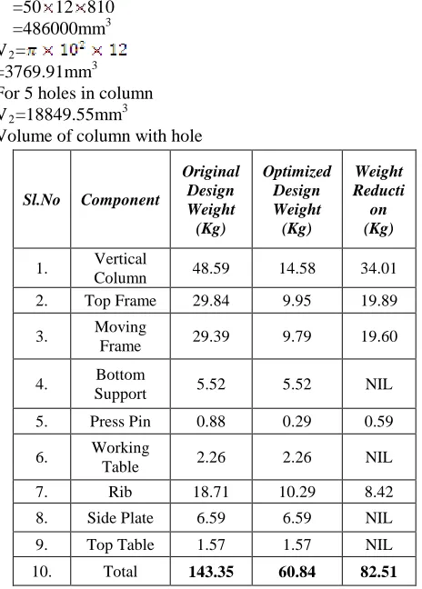
Volume of column without hole consideration
V1=l ……… (8.1)
=50 12 810 =486000mm3 V2=
=3769.91mm3 For 5 holes in column V2=18849.55mm3
Volume of column with hole
Vc= V1- V2……….. (8.2) =467150.44mm3
We know that density is ………... (8.3)
m=
=7801 467150.44 =3.644 kg
For four column its mass is m=14.57kg
Similarly for Frames and Ribs and for supporting plate we obtained as shown in table.1
Table 1: Shows comparison of original design and optimized design weight
Percentage of weight reduction
= (Weight reduction / Original design weight) 100 = (82.51 / 143.35) 100
= 57.56%
Percentage of weight reduction we found up to 57.56%
6. Calculation of Cost Reduction for
H-Frame
Type Hydraulic Press
6.1 Total cost before optimization
Material cost per kg = Rs.58 Fabrication cost per kg = Rs.30
Material cost for 143.35 kg = Rs.8314.8 Fabrication cost for 143.35 kg = Rs.4300.5 Total = Rs.12615
6.2 Total cost after optimization
Material cost per kg = Rs.58 Fabrication cost per kg = Rs.30
Material cost for 60.84 kg = Rs.3528.72 Fabrication cost for 60.84 kg = Rs.1825 Total = Rs.5354
6.3 Cost reduction of hydraulic press
Percentage of material cost reduction = (12615 – 5354) / 12615 * 100
= 57.55%
Percentage of cost reduction we got up to 57.55%
Table 2: Comparison of Results for different parameters
Sl.No Component
Original Design Weight
(Kg)
Optimized Design Weight (Kg)
Weight Reducti on (Kg)
1. Vertical
Column 48.59 14.58 34.01 2. Top Frame 29.84 9.95 19.89 3. Moving
Frame 29.39 9.79 19.60 4. Bottom
Support 5.52 5.52 NIL 5. Press Pin 0.88 0.29 0.59 6. Working
ISSN 2348 – 7968
7. Conclusion
In this project it has been compared original design of H frame type hydraulic press with design that have been optimized by using software tool (ANSYS) it has been demonstrate that, under the same loading conditions, constraints, and intended design purpose ANSYS indentifies a lighter design with reduced material cost. In this project, it has been shown a 57.56%weight reduction & 57.55%cost reduction of the H-frame type hydraulic press, which was achieved by changing the dimensions of the vertical column, moving & top table, and working plate while maintaining structural balance of the hydraulic press and without affecting on performance.
References
[1] Muni Prabaharan and Amarnath V.(2011)-“Structural Optimization of 5Ton Hydraulic Press and Scrap Baling Press for Cost Reduction by Topology” International Journal of Modeling and Optimization, Vol. 1, No. 3, August 2011.
[2] B.Parthiban, P.Eazhumali, S.Karthi, P.Kalimuthu(2014)-“Design And Analysis of C Type Hydraulic Press Structure and Cylinder”. Vol.2 Issue.3, March2014.Pgs: 47-56 International Journal of Research in Aeronautical and Mechanical Engineering.
[3] Satish.G.S, S.Kshirsagar, Nitin.B, Chetan.M(2014)-“Structural Optimization of Hooping Plate Of 400ton Cotton Baling Press For Cost Reduction”. International Journal of Pure and Applied Research in Engineering and Technology, 2014; Volume 2 (9): 379-389.
[4] Rajdipsinh.G,Vaghela,Ravi.C,Patel,( 2014)- “A Review on Design & Analysis of C-Frame of Pneumatic Power Press Using FEA”. IJSRD - International Journal for Scientific Research & Development| Vol. 1, Issue 11, 2014 | ISSN (online): 2321-0613.
[5] H.N.Chauhan, M.P.Bambhania (2013) – “Design & Analysis of Frame of 63 Ton Power Press Machine by Using Finite Element Method” Volume: 3 | Issue: 7 | July 2013 | ISSN - 2249-555X Indian Journal of Applied Research.
Santoshkumar S. M-He completed his Bachelors degree Engineering in Mechanical from G.I.T Engg. College, Belgaum affiliated to VTU Karnataka in 2010, and presently he is pursuing his Masters degree in Machine Design from M.M. Engg.College,Belgaum at Vishweshwarayya Technological University, Belgaum. His areas of interest are Composite Mechanics, Mechanical vibration, Dynamics of machines.
Yogita N. Potdar-She completed her Bachelors degree in Engineering in Industrial Production from G.I.T Engg. College, Belgaum affiliated to VTU BELGAUM in 2008, obtained her Masters degree in Design Engineering from K.L.E. Engg College, Belgaum in 2010, at Vishweshwarayya Technological University, Belgaum. Her areas of interest are Machine Design, Tribology, Mechatronics.
A. C. Mattikalli- He completed his Bachelors degree Engineering in Mechanical from G.I.T Engg. College, Belgaum affiliated to VTU Karnataka and obtained his Masters degree in Design Engineering from K.L.E. Engg College, Belgaum in 2007, at Vishweshwarayya Technological University, Belgaum. He is pursuing Ph.D in VTU, Belgaum. His areas of interest are Advanced Dynamics of machine, Expt. stress analysis, Design of machine elements.
Sl.
No Parameters
Before Optimizatio
n
After Optimizatio
n
1.
Max. Stress Developed in
the H-Frame type hydraulic press
51.197 MPa 88.505 MPa
2.
Max. Deformation of
Frames of the hydraulic press
0.03704 mm 0.066983 mm 3. Yield Strength 250 MPa 250 MPa 4. Factor Of
Safety 4.88 2.82 5. Weight Of The