IJEDR1502146
International Journal of Engineering Development and Research (www.ijedr.org)816
Abstract - Image scaling is one of the most widely used methods in image processing applications and deals with the resizing of an image. Image scaling deals with the trade-off between efficiency, sharpness and smoothness. So this paper presents a low complexity, low memory requirement, high quality image after scaling by using an efficient edge enhanced algorithm. The proposed algorithm consists of a sharpening filter, bilinear interpolation and an edge detector. Sharpening filter is used to reduce the blurred images and sobel operator is used as edge detector to identify the edges and to reduce the noise effects in an image. And a simplified bilinear interpolation technique is used to reduce silicon cost.Keywords - Sharpening Filter, Edge detector, Bilinear Interpolation
________________________________________________________________________________________________________
I. INTRODUCTION
Image scaling is a very important technique and is widely used in image processing applications. Image scaling is all about resizing of a digital image. Scaling deals with the trade off between efficiency, sharpness and smoothness. Image scaling is a non-trivial process. Scaling reduces or enlarges the size of the image by changing the number of pixels. Increasing the size of an image is called upsampling and reducing the size of an image is called downsampling.
Image scaling is used in computer graphics, digital image devices and video applications, as the use of these applications grow up, significance of image scaling becomes more outstanding.
Scaling up an image is generally done to enlarge the image, so as to make the smaller images fit into full screen mode. And scaling down is done to shrink the image, so as to make the image fit into small size LCD panel. A number of image scaling algorithms have been proposed, the most popularly used methods are nearest neighbour algorithm, bilinear interpolation algorithm and bicubic interpolation algorithm.
The image scaling algorithms are divided into two types: Polynomial and non-polynomial based method. Nearest neighbour algorithm is a polynomial based method. Scaling using bilinear and bicubic interpolation algorithms are the other polynomial based method. These methods can be easily implemented in hardware but results in blocking and blurring effects. Other non-polynomial based methods have been proposed, these methods improve the quality of image by using some of the efficient techniques such as bilinear filter, curvature interpolation. These methods improve the image quality while reducing the blocking and blurring effects. These methods provide a high quality image but have high complexity and high memory requirements.
II.PROPOSED SCALING ALGORITHM
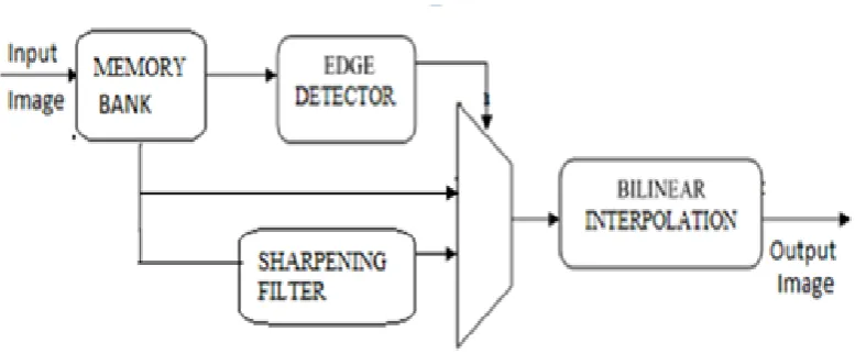
In image scaling or resizing of an image, the sharpening filter is used to reduce the blurring effects. The edge detector is used to detect sharp discontinuities in an image. A register bank is used in this project in order to store the gray scale values of images. And bilinear interpolation method is used for image zooming. The gray scale image values are given to the memory bank, Fig 1. Shows the block diagram of the proposed scaling algorithm.
IJEDR1502146
International Journal of Engineering Development and Research (www.ijedr.org)817
Fig 1: Block diagram of the proposed scalar algorithmA. Sharpening Filter
Sharpening is an enhancement technique that highlights the edges , line structures and other fine details in an image Sharpening of an image consists of adding a signal to the original image , the signal that is added is proportional to high pass filter version of original image. The original image is first filtered out by high pass filter, and then the output of high pass filter is added to the original image, which thus results in a sharpened image. The choice of high pass filter is one of the key factor in sharpening process. High pass filter amplifies noise and makes the image sharper. The filters that are used for sharpening process, changes the pixel value by considering the values of neighbouring pixels.
Laplacian filter is an example of second order derivative method. Sharp discontinuity in the image such as noise will be enhanced by using this operator.
Laplacian highlights sharp discontinuities and in the output image the grey line represents the edges in an image with a black background. The laplacian operator is given by the convolution between the image and a kernel. The filtered image is added with the original image to obtain the sharpened image. Laplacian filter is a form of isotropic filter, i.e, the rotation of the filter is invariant
Laplacian kernel invariant to 90˚ rotation:
0 1 0 1 -4 1 0 1 0
Laplacian kernel invariant to 45˚ rotation:
1 1 1 1 -8 1 1 1 1
For 1D, the second order derivative is given by
( ) ( ) ( ) ( )
( ) ( ) ( ) ( )
The second order derivative have stronger response and are good for finding fine details in an image and are used for image enhancement. The second order derivative is more sensitive to intensity variation and the derivative depends upon the direction along which it is evaluated.
Adding both the equations, (1) & (2) we get ( )
IJEDR1502146
International Journal of Engineering Development and Research (www.ijedr.org)818
Each of the neighbourhood pixel is multiplied by the weight and then we add them together to obtain the output.
( ) , ( ) ( ) ( ) ( ) ( ) ( ) ( ) ( ) ( ) ( )- , ( ) ( ) ( ) ( )
( )- ( )
Where, is the weight of neighbourhood input pixel, is rotated by 180˚ to form inverted mask. And is input pixel. B. Edge Detector
Edges usually represent object boundaries or edges are discontinuities in image with strong intensity contrast, where the pixel value changes abruptly. Edges are always important characteristics of an image. In order to emphasise more on edges in an image then some weights in the filter has to be negative. For the difference in the input pixel values, sum of sets of weights tends to produce zero output.
The sobel operator uses two 3x3 kernels, one kernel calculates the gradient in x- direction (horizontal) and other gradient in y-direction (vertical). The two kernels used are 0 deg and 90 deg convolution kernel. Each of these kernels is convolved with the original image and calculates the gradient at each point and then increases the image intensity at each point. The two kernels are
Sobel operator is magnitude of gradient given by
√ ( ) ( ) ( ) ( ) ( ) ( ) ( )
( ) ( )
( ) ( ) ( ) ( ) ( )
( ) ( )
C.Bilinear Interpolation
Bilinear interpolation method is an extension of linear interpolation. This method is opted because of its high quality and low complexity. This interpolation method, firstly it performs linear interpolation in one direction (horizontal) and then in another direction (vertical). In this method the weighted average of the nearest four pixel values is taken as input and then determines the intensity and provides an output.
The output pixel ( ) is calculated by performing linear interpolation operation in both x and y direction. Both and are scaled parameters in horizontal and vertical directions and both of which can be specified by the user.
IJEDR1502146
International Journal of Engineering Development and Research (www.ijedr.org)819
Fig 2 : Bilinear interpolationwhere M is the width of the original image and N is the height .The temporary pixel values is calculated in x direction. ( ) ( ) ( ) ( ) ( )
( ) ( ) ( ) ( ) ( )
The output pixel value is obtained by performing linear interpolation in y direction. The output pixel ( ) is obtained by ( ) ( ) ( ) ( ) ( )
The output pixel can be calculated by taking both horizontal and vertical interpolations and obtained by only one stage as, ( ) ( )( ) ( ) ( ) ( ) ( ) ( )
( ) ( )
and are zooming ratios in horizontal and vertical directions. It is selected because of its computational efficiency and quantitative stability. Because of its simple architecture and less complexity, it is efficient for VLSI implementation.
The computing resources of this interpolation method costs eight multiply, four subtract and three addition operations. So eight multipliers and seven adders are required for its implementation.
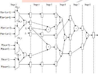
In order to reduce the cost of computing resources algebraic manipulation and a hardware sharing technique is used. In order to reduce the hardware cost or the silicon cost we are using a hardware sharing technique and also to reduce the delay path. The architecture of the bilinear interpolation is shown below
Fig 3 : Architecture of Bilinear Interpolation
IJEDR1502146
International Journal of Engineering Development and Research (www.ijedr.org)820
* , ( ) ( ) ( ) ( )- ( ) ( )+, ( ) ( )- ( ) ( )
* , ( ) ( )- ( ) ( ( ) ( ) ( )+ ( ( ) ( ) ( ) ( )
The output obtained from bilinear interpolation, i.e, eqn (15) can be simplified by algebraic manipulation. The equation (15) contains ( ) ( ) twice, so one of the calculation function can be reduced. So by addition of three registers the function ( ) ( ) can be reduced by the hardware sharing technique. The calculation function is replaced; i.e, one multiplexer and two adders are reduced. Since the values of & are floating point numbers from 0 to 1 and the pixel values are integer from 0 to 255. To reduce the computation cost, low cost integer calculation is done. Firstly, we shift & left by 8bits, so that the values of & are multiplied by 256. After this multiplication the highest 8bits obtained are approximated integer values of equation. The target result ( ) is computed by low cost integer addition, subtraction and multiplication. So by this approximation technique the floating point computation is replaced by integer computation.
.
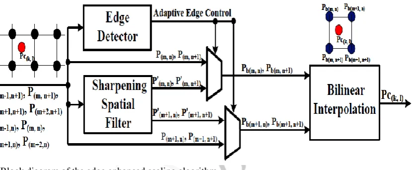
Fig 4: Block diagram of the edge enhanced scaling algorithm
III.SIMULATION RESULTS
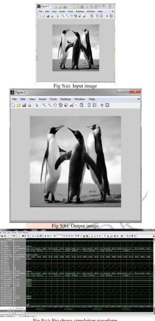
The MATLAB tool is used to evaluate the performance of the prposed scalar architecture. Xilinix ISE tool is used for synthesis of the design and SPARTEN 3E is used for FPGA implementation.
Image output after scaling up of image:
IJEDR1502146
International Journal of Engineering Development and Research (www.ijedr.org)821
Fig 5(a): Input imageFig 5(b): Output image
Fig 5(c): Fig shows simulation waveform
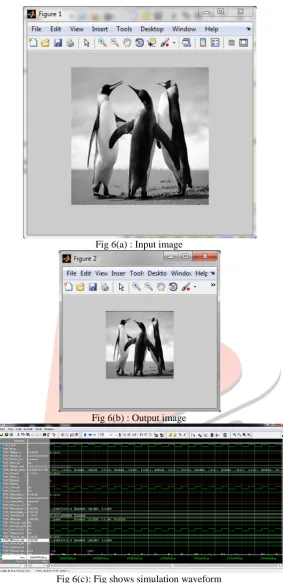
6. Image output after scaling down of image:
IJEDR1502146
International Journal of Engineering Development and Research (www.ijedr.org)822
Fig 6(a) : Input imageFig 6(b) : Output image
Fig 6(c): Fig shows simulation waveform
IV.CONCLUSION
In this paper a low cost, low memory requirement, low complexity , high quality and high performance scalar architecture is proposed..In this paper a convolution filter and sobel operator are introduced to reduce blurred images and the presence of noise in image is also reduced to some extent. And hardware sharing technique for bilinear interpolation is used in order to reduce the silicon cost. The design was simulated by using the simulator Modelsim SE 6.3f and synthesised using Xilinx ISE 12.2. MATLAB tool is used to obtain the output image.
ACKNOWLEDGMENT
IJEDR1502146
International Journal of Engineering Development and Research (www.ijedr.org)823
REFERENCES
[1] Shin–Lun Chen “VLSI Implementation of an Adaptive Edge-Enhanced Image Scalar for Real –Time Multimedia application” IEEE Trans. circuits and systems for video technology,2013.
[2] Shin–Lun Chen “VLSI implementation of a low-Cost High-quality Image Scaling Processor”, IEEE Trans. circuits and system, vol.60, no.1, Jan.2013 .
[3] C. C. Huang, P. Y. Chen, and C. H. Ma, “A novel interpolation chip for real-time multimedia application,” IEEE Transaction on Circuits and Systems for Video Technology, Vol. 22, no. 10 , pp. 1512-1525, Oct. 2012.
[4] Christos Gentsos, Calliope-Louisa Sotiropoulou and Spiridon Nikolaidis “Real- Time Canny Edge Detection Parallel Implementation for FPGAs” in Electronics, Circuits, and systems (ICECS), 2010 17th IEEE International Conference.
[5] Fahad Alzahrani , Tom Chen “A Real-Time High Performance Edge Detector for Computer Vision Applications ” in Proc. of Design Automation Conference, 1997. Proceedings of the ASP-DAC '97 Asia and South Pacific .
[6] Chung-Chi Lin, Ming-Hwa Sheu, Huann-Keng Chiang , Chishyan Lia Zeng-Chaun Wu and Wen-Kai Tsai “An Efficient Architecture of Extended Linear Interpolation for Image Processing ” in Journal of Information Science And Engineering 26, 631-648 (2010)
[7] R.Sundar “An Efficient Low cost Image scaling Technique for less power Consumption ” in International Journal of Advance Research in Computer Science and Management Studies Volume 2, Issue 2, February 2014.
[8]Ms. Abhilasha Bhatnagar , Dr.R.Ramakishore “Spline based Interpolation methods For Image Magnification ” in International Journal of Scientific & Engineering Research, Volume 4, Issue 5, May-2013.
[9]Robert G..Keys “Cubic Convolution Interpolation for Digital Image Processing” in IEEE Transactions on Acoustics, Speech , and Signal Processing, VOL. ASSP-29, NO. 6, DECEMBER 1981
[10] Shih-Lun Chen, Hong-Yi Huang and Ching-Hsing Luo, “A Low-Cost High-Quality Adaptive Scalar for
Real-Time Multimedia Applications” in IEEE Transactions on circuits and systems for video technology, VOL 21, NO. 11, November 2011.
[11] G.Manoj kannan,A.Manoj kumar,R.Mareeswaran, J.Kanimozhi “VLSI Architecture of Pipelined Adaptive Edge-Enhanced Image Scalar for Image Processing Applications” in International Journal of Innovative Research in Science, Engineering and Technology Volume 3, Special Issue 3, March 2014
[12] M.Saranya, V.Meenakshi, “VLSI Based Image Zooming Application by a Novel Adaptive Edge Enhancement Technique”, in International Journal of Advanced Research in Electrical, Electronics and Instrumentation Engineering, Vol. 3, Issue 4, April 2014