CAXTON OKOH
A FRAMEWORK DEVELOPMENT TO PREDICT REMAINING
USEFUL LIFE OF A GAS TURBINE MECHANICAL COMPONENT
SCHOOL OF AEROSPACE, TRANSPORT AND
MANUFACTURING
Manufacturing Department
DOCTOR OF PHILOSOPHY, PhD
Academic Year: 2013 - 2017
Supervisors: Professor Rajkumar Roy, Professor J
Örn Mehnen
September 2017
SCHOOL OF AEROSPACE, TRANSPORT AND
MANUFACTURING
Manufacturing Department
DOCTOR OF PHILOSOPHY, PhD
Academic Year 2013 - 2017
CAXTON OKOH
A Framework Development to Predict Remaining Useful
Life of a Gas Turbine Mechanical Component
Supervisors: Professor Rajkumar Roy, Professor J
Örn Mehnen
September 2017
This thesis is submitted in partial fulfilment of the requirements for
the degree of Doctor of Philosophy
© Cranfield University 2017. All rights reserved. No part of this
publication may be reproduced without the written permission of the
I
ABSTRACT
Power-by-the-hour is a performance based offering for delivering outstanding service to operators of civil aviation aircraft. Operators need to guarantee to minimise downtime, reduce service cost and ensure value for money which requires an innovative advanced technology for predictive maintenance. Predictability, availability and reliability of the engine offers better service for operators, and the need to estimate the expected component failure prior to failure occurrence requires a proactive approach to predict the remaining useful life of components within an assembly.
This research offers a framework for component remaining useful life prediction using assembly level data. The thesis presents a critical analysis on literature identifying the Weibull method, statistical technique and data-driven methodology relating to remaining useful life prediction, which are used in this research. The AS-IS practice captures relevant information based on the investigation conducted in the aerospace industry. The analysis of maintenance cycles relates to the examination of high-level events for engine availability, whereby more communications with industry showcase a through-life performance timeline visualisation. Overhaul sequence and activities are presented to gain insights of the timeline visualisation.
The thesis covers the framework development and application to gas turbine single stage assembly, repair and replacement of components in single stage assembly, and multiple stage assembly. The framework is demonstrated in aerospace engines and power generation engines. The framework developed enables and supports domain experts to quickly respond to, and prepare for maintenance and on-time delivery of spare parts.
The results of the framework show the probability of failure based on a pair of error values using the corresponding Scale and Shape parameters. The probability of failure is transformed into the remaining useful life depicting a typical Weibull distribution. The resulting Weibull curves developed with three scenarios
II
of the case shows there are components renewals, therefore, the remaining useful life of the components are established. The framework is validated and verified through a case study with three scenarios and also through expert judgement.
III
ACKNOWLEDGEMENTS
I appreciate God almighty for the grace and wisdom to complete this programme. I would like to appreciate Professor Rajkumar Roy and Professor Jörn Mehnen for the opportunity to undergo this PhD programme under their supervision. Their support, advice and encouragement had always given me innovative perceptions.
I am grateful to the industry sponsor and supervisor, Mr. Andrew Harrison who provided me with the projects, case studies and resources for the research. Thank you for your immense support whilst undertaking these projects. And to the T900 Life Cycle, Functional System and Safety and Reliability Engineering groups for the support during this research.
My gratitude goes to my colleagues at the Through-life Engineering Service (TES) centre and the Manufacturing Department at Cranfield University. Thanks to the staffs at the TES centre and the Manufacturing Department for their support. My appreciation goes to the individuals who took their time to conduct validations of the work.
Appreciation to Rolls-Royce and EPSRC Research Council for sponsoring this research project conducted at the EPSRC Centre for Innovative Manufacturing in Through-Life Engineering Services at Cranfield University.
My deepest gratitude goes to my wife Golden and son Joshua for their unconditional love and immense support all through this programme.
IV
PUBLICATIONS
Publications that contributed to this research
i. Okoh, C., Roy, R., and Mehnen, J. (2017), Predictive Maintenance Modelling for Through-Life Engineering Services, Procedia CIRP. The 5th International Conference on Through-life Engineering Services. DOI: 10.1016/j.procir.2016.09.033
https://www.sciencedirect.com/science/article/pii/S2212827116309726 ii. Okoh, C., Roy, R., and Mehnen, J. (2017), Maintenance Informatics
Dashboard Design for Through-Life Engineering Services, Procedia CIRP. The 5th International Conference on Through-life Engineering Services. DOI:10.1016/j.procir.2016.09.019
https://www.sciencedirect.com/science/article/pii/S2212827116309532 iii. Okoh, C., Roy, R., Mehnen, J. and Redding, L., and Harrison, A. (2014).
Development of an Ontology for Aerospace Engine Components Degradation in Service. 6th International Conference on Knowledge Engineering and Ontology Development, Rome, Italy. DOI: 10.5220/0005090201080119
https://www.researchgate.net/publication/280300563_Development_of_an_
Ontology_for_Aerospace_Engine_Components_Degradation_in_Service
iv. Okoh, C., Roy, R., Mehnen, J. and Redding, L. (2014), Overview of Remaining Useful Life Prediction Techniques in Through-life Engineering Services. Procedia CIRP, vol.16, pp. 158-163. The 6th CIRP Conference on Industrial Product-Service Systems. DOI: 10.1016/j.procir.2014.02.006 https://www.sciencedirect.com/science/article/pii/S2212827114001140 v. Roy, R., Mehnen, J., Addepalli, S., Redding, L., Tinsley, L. and Okoh, C.,
(2014). Service Knowledge Capture and Reuse. Procedia CIRP, 16, pp.9-14. The 6th CIRP Conference on Industrial Product-Service Systems. DOI: 10.1016/j.procir.2014.03.001
V
TABLE OF CONTENTS
ABSTRACT ... i ACKNOWLEDGEMENTS... iii PUBLICATIONS ... iv TABLE OF CONTENTS ... v LIST OF FIGURES ... ixLIST OF TABLES ... xiii
LIST OF ABBREVIATIONS ... xv
LIST OF SYMBOLS ... xvii
1 INTRODUCTION ... 1
1.1 Motivation and scope ... 3
1.2 Problem definition ... 6 1.3 Research questions ... 8 1.4 Research sponsors ... 8 1.5 Thesis structure ... 10 1.6 Summary ... 12 2 LITERATURE REVIEW ... 13 2.1 Methodology ... 13
2.2 Through-life Engineering Services ... 16
2.3 Degradation Mechanisms ... 17
2.3.1 Corrosion ... 18
2.3.2 Deformation ... 18
2.3.3 Fracture ... 19
2.3.4 Wear ... 19
2.4 Taxonomy and Ontology ... 20
2.5 Overview of maintenance strategies ... 20
2.6 Predictive maintenance ... 22
2.6.1 Component degradation diagnostics ... 23
2.6.2 Component degradation prognostics ... 26
2.7 Visualisation ... 26
2.8 Weibull Parameter estimation ... 27
2.9 Modelling ... 27
2.10 Renewal theory ... 27
2.11 Performance metric ... 29
2.12 Renewal with repaired components ... 30
2.13 Remaining useful life prediction approaches ... 31
2.13.1 Prediction Methods ... 33
2.13.2 Prediction techniques ... 37
VI
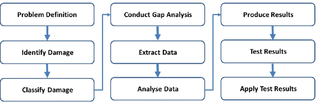
2.14 Research gap analysis ... 51
2.15 Summary ... 54
3 RESEARCH AIM, OBJECTIVES AND METHODOLOGY ... 56
3.1 Research aim and objectives ... 56
3.2 Research methodology ... 58
3.3 Research method selection and rationale ... 59
3.3.1 Research design ... 60
3.3.2 Research purpose ... 61
3.3.3 Research strategy ... 62
3.3.4 Data collection strategy ... 64
3.4 Research Process ... 68
3.5 Research methodology adopted ... 70
3.5.1 Phase 1: Understanding context and current practices ... 70
3.5.2 Phase 2: Aero component based framework development ... 72
3.5.3 Phase 3: Framework validation ... 74
3.6 Summary ... 76
4 CURRENT INDUSTRY PRACTICE ... 77
4.1 Scope of participants’ selection ... 77
4.2 Methodology to develop interview questions ... 79
4.2.1 Pilot research ... 80
4.2.2 Conducting the data collection ... 81
4.3 Analysis of interviews and findings ... 85
4.3.1 Comparative analysis of participants’ views ... 89
4.4 Description of current practice in industry ... 89
4.4.1 Index representation of products, components, features and mechanisms ... 100
4.5 Key observations ... 101
4.6 Summary ... 102
5 ANALYSIS OF MAINTENANCE CYCLES ... 104
5.1 Description of events ... 105
5.2 Description of data collection method ... 106
5.3 Description of overhaul ... 107
5.4 Methodology for visualising maintenance cycles ... 109
5.5 Analysis of the historical through-life data ... 111
5.5.1 Criteria to determine levels of events ... 112
5.5.2 Interviews and Brainstorming sessions ... 113
5.5.3 Requirement analysis for the maintenance cycles design ... 116
5.6 Design of maintenance cycle event visualisation ... 118
5.6.1 Entity relationship diagram ... 118
5.6.2 Database logical schema ... 120
VII
5.6.4 Initial interface design ... 122
5.7 Development of the interface design ... 123
5.8 Summary ... 132
6 THROUGH-LIFE PERFORMANCE FOR REMAINING USEFUL LIFE PREDICTION ... 133
6.1 Methodology for the proposed framework ... 133
6.2 A framework for WTPPM ... 135
6.2.1 Prepared data ... 136
6.2.2 Model selection ... 139
6.2.3 Weibull Parameter estimation ... 141
6.2.4 Through-life performance modelling ... 145
6.2.5 Performance metric evaluation ... 151
6.2.6 The process to select optimal η and β parameters ... 154
6.2.7 Through-life performance model evaluation ... 155
6.2.8 Cost-benefit analysis ... 157
6.3 Summary ... 157
7 CASE STUDY SCENARIOS AND RESULTS ... 159
7.1 Scenario one - Single stage turbine ... 165
7.2 Scenario two - Repair of single stage turbine for aero engine ... 176
7.2.1 Generating repair failure data ... 176
7.2.2 The procedure for replacement with repaired components ... 177
7.2.3 The results of the repaired replacement ... 179
7.3 Scenario three - Multiple of four stage turbines ... 184
7.4 Summary ... 195
8 VALIDATION AND VERIFICATION ... 196
8.1 Internal verification ... 196
8.2 Case study ... 199
8.3 Qualitative validation ... 200
8.4 Quantitative validation ... 215
8.5 Summary ... 216
9 DISCUSSION, CONCLUSIONS AND FUTURE WORK... 218
9.1 Discussion of the research findings ... 218
9.1.1 Literature review ... 218
9.1.2 Research methodology ... 219
9.1.3 Current practice in industry ... 221
9.1.4 Analysis of through-life maintenance cycles ... 222
9.1.5 A framework of Through-life Performance Prediction Model ... 223
9.1.6 Case study scenarios ... 226
9.1.7 Verification and Validation ... 228
9.1.8 Implementation issues ... 229
VIII
9.2.1 Research contributions ... 230
9.2.2 Research limitations ... 231
9.3 Fulfilling research aim and objectives ... 232
9.4 Recommendations for future research ... 234
9.5 Conclusions ... 235
REFERENCES ... 239
Permission to use image ... 258
RUL techniques from Literature Review ... 259
Methods grouped based on types of data ... 268
Grouped approaches, techniques and methods for input data 269 Current Practice Historical Data ... 270
Degradation mechanism taxonomy ... 272
Master Index Representation ... 274
Brainstorming Questionnaire ... 277
Data dictionary ... 281
Model Class Diagram ... 282
Flowchart for the Through-life model ... 283
Case Study Scenarios Results ... 288
Validation and Verification of Technique ... 315
IX
LIST OF FIGURES
Figure 1-1: A schematic relationship hierarchy ... 4
Figure 1-2: Relationship process for existing and proposed scenario ... 7
Figure 1-3 Thesis structure... 10
Figure 2-1 Literature review methodology ... 14
Figure 2-2 The number of literatures on RUL per year ... 15
Figure 2-3: A comparison of documents by authors ... 15
Figure 2-4: Comparative literature by (A) type and (B) subject area ... 16
Figure 2-5 Metal discs showing corrosion on the surface ... 18
Figure 2-6 Bearing external ring failure and inner ring failure with fracture (Source: (Medjaher et al, 2012)) (see appendix A for permission) ... 19
Figure 2-7 A proposed taxonomy of maintenance strategies ... 21
Figure 2-8: A taxonomy of condition-based maintenance ... 23
Figure 2-9 Categorisation of RUL prediction methodologies ... 31
Figure 2-10: RUL showing component health index against time ... 32
Figure 2-11: Weibull bathtub model with state transition approach ... 36
Figure 3-1: Layout of the methodology section... 58
Figure 3-2: The research selection approach (the blue boxes with white texts were used in this thesis) ... 59
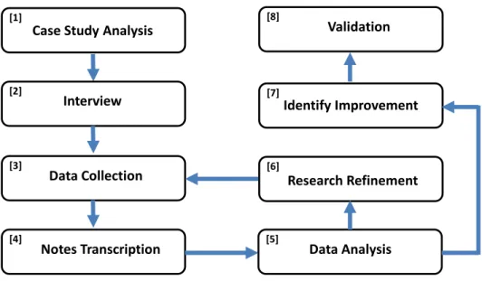
Figure 3-3: The research process. Source: (Walliman, 2005) ... 69
Figure 3-4: Adopted research methodology (Light blue colour is the phase 1, pink colour is the phase 2 and purple colour represents activities conducted in phase 3) ... 75
Figure 4-1 The systematic research methodology for phase two ... 79
Figure 4-2 Process for information gathering from organisation interaction ... 82
Figure 4-3 Outlined relationship of the AS-IS practice from product to mechanism ... 92
Figure 4-4 The relationship between failure cause, failure mode and failure effect. (Adapted from Source: (Rausand and Høyland, 2004)) ... 93
X
Figure 4-6 Representation of iterative reality check process ... 97
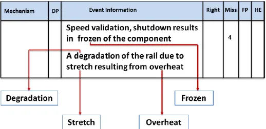
Figure 4-7 Samples of relevant concepts analysis (“4” indicates missed keywords) ... 99
Figure 4-8 Identification of relevant concepts (“4” means right keywords found) ... 99
Figure 5-1: Events occurrences and maintenance durations ... 112
Figure 5-2: Events classified based on key groups ... 116
Figure 5-3: Events timeline user stories presented at the brainstorming sessions ... 117
Figure 5-4: Event visualisation use case diagram ... 118
Figure 5-5: Entity Relationship Diagram (“1” means one and “M” signifies many) ... 119
Figure 5-6: Database Logical Schema ... 120
Figure 5-7: Conceptual Class Diagram (“*” signifies many by connecting two table with primary and foreign key attribute) ... 121
Figure 5-8: Conceptual Class Diagram (Group Entity) with subclass and superclass ... 122
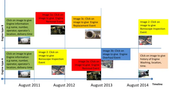
Figure 5-9: Initial interface design with Engine number, levels and year of service ... 123
Figure 5-10: Architecture of the events timeline visualisation ... 124
Figure 5-11: A snapshot of the SQL script to return maintenance activities ... 127
Figure 5-12: Summarisation of Helicopter view events ... 128
Figure 5-13: Summarisation Fisheye view with hover and zoom... 129
Figure 5-14: Fisheye view with click and display entire events stream ... 129
Figure 5-15: Selection of disruption from the drop down menu ... 130
Figure 5-16: Drill down of disruption ... 130
Figure 5-17: Display of only selected disruption events ... 131
Figure 5-18: Inspection key selected ... 131
Figure 5-19: Inspection group event ... 132
Figure 6-1: Fundamental through-life performance approach to RUL estimation ... 136
XI
Figure 6-2: Conceptual modelling of through-life performance of components for
data generation ... 138
Figure 6-3: Detailed model of through-life performance ... 139
Figure 6-4: An outline of a modelled TPM for through-life performance operation ... 147
Figure 6-5: The flowchart to modelling each segment of TPM ... 148
Figure 6-6: Approach to calculate probability distribution and RUL; ‘e in green’ means acceptable and ‘e in red’ is unacceptable error values ... 152
Figure 6-7: Enumeration of error values, estimated η and β parameters ... 153
Figure 6-8: Borderline for the selection of low error values ... 154
Figure 6-9: Optimised estimated η and β parameters with error values ... 155
Figure 6-10: A Probability of failure distribution ... 155
Figure 6-11: A Weibull representation of the RUL ... 156
Figure 7-1 Graph with same observed and predicted rejection rates and time ... 160
Figure 7-2 MLE: Normal and optimised error values of η and β parameters to check the approach returns the expected outcome ... 160
Figure 7-3 LSM: Normal and optimised error values of η and β parameters to check the approach returns the expected outcome ... 161
Figure 7-4 MLE: 3D visualisation of normal and optimised error values with η and β parameters ... 162
Figure 7-5 LSM: 3D visualisation of normal and optimised error values with η and β parameters ... 163
Figure 7-6 Probability of failure and RUL of optimised η and β parameters ... 164
Figure 7-7 Framework with different scenarios ... 165
Figure 7-8 Single system (A) LSM β = 1.6 and (B) MLE β = 1.5 with predicted and observed values on Probability of failure ... 168
Figure 7-9 Single system (a) LSM β = 1.6 and (b) MLE β = 1.5 with error values, η and β parameters ... 170
Figure 7-10 Single system (a) LSM β = 1.6 and (b) MLE β = 1.5 with error values and optimised η and β parameters ... 171
Figure 7-11 RUL for single system (a) LSM β = 1.6 and (b) MLE β = 1.5 for optimised η and β parameters ... 172
XII
Figure 7-12 Cost threshold for components assembly rejection ... 172
Figure 7-13 MLE multiple systems: β = 1.5 with error values, realistic η and β with ... 174
Figure 7-14 3D surface map: β = 1.5 with errors values, realistic η and β ... 175
Figure 7-15 RUL: MLE multiple systems: β = 1.5 ... 175
Figure 7-16 Framework for incorporating repair components ... 176
Figure 7-17 A typical trend of new, reused, degraded and repaired components ... 177
Figure 7-18 Normal, optimised and repair optimised for error values, η and β parameters ... 181
Figure 7-19 3D shape of normal, optimised and repair optimised error values, η and β parameters ... 182
Figure 7-20 RUL for new η,β: 6073,1.2 and repaired η,β: 4968,1.5. The red represents the repair and blue indicates new components. ... 184
Figure 7-21 Failure rate and RUL for optimised new and repaired η,β ... 184
Figure 7-22 Framework for multiple stage turbine ... 185
Figure 7-23 Optimised error values, η and β parameters of multiple stage turbine ... 189
Figure 7-24 Overall results of multiple stage turbine probability of failure and RUL ... 191
XIII
LIST OF TABLES
Table 2-1 Failure mechanisms in vanes (Boyce, 2006) ... 25
Table 2-2 Methodology, Requirements, merits and demerits ... 51
Table 3-1: Mitigation strategies ... 67
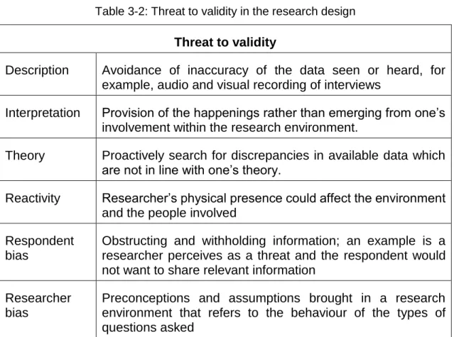
Table 3-2: Threat to validity in the research design ... 68
Table 4-1 Experts, role space and experience ... 78
Table 4-2 Sample concepts, meanings and questions ... 95
Table 4-3 Extraction of concepts from relationships ... 100
Table 5-1 Interview and brainstorming sessions personnel ... 111
Table 5-2 Criteria for Levels ... 112
Table 5-3 Extracted events from brainstorming workshop ... 114
Table 5-4 Grouped events and colour names ... 116
Table 5-5 Key: Colour and meanings ... 128
Table 6-1 Sample of pre-processed data (model-building data) ... 137
Table 7-1 The 𝛈 and β outcomes of the LSM and MLE ... 159
Table 7-2 The number of rejected components, η and β outcomes of the LSM and MLE ... 159
Table 7-3 Data with multiple engines and overhaul state used for the analysis (validation data) ... 166
Table 7-4 The rejected components, η and β outcomes for LSM and MLE methods ... 167
Table 7-5 Outcomes of the optimised values from LSM and MLE methods ... 171
Table 7-6 Estimated parameters for new and repair data ... 178
Table 7-7 Estimated parameters for new and repair data ... 178
Table 7-8 The η and β outcomes of new and repaired rejected components with LSM ... 179
Table 7-9 Outcomes of the optimised values from LSM methods ... 183
Table 7-10 Estimated parameters (Barringer & Kotlyar 1996) ... 185
Table 7-11 Data with multiple engines and overhaul state used for the analysis (validation data) ... 186
XIV
Table 7-12 Failure data with predicted rejection data for the turbine stages .. 187
Table 7-13 Failure data values with optimised values ... 187
Table 7-14 Failure data from literature with optimised values ... 192
Table 8-1 Calculation of the number of components degraded ... 197
Table 8-2 Technique for conducted error calculation. ... 198
Table 8-3 Presentation of a range of η and β parameters ... 198
Table 8-4 Assessment of probability of failure ... 198
Table 8-5 Assessment of remaining useful life ... 198
Table 8-6 Estimation of scale and slope parameters ... 199
Table 8-7 Calculation of cost to scrap entire components in an assembly ... 199
Table 8-8 Failure data values with optimised values ... 201
Table 8-9 Assessing the prediction modelling logic in the framework ... 202
Table 8-10 Assessing the generality of the framework ... 203
Table 8-11 Assessing the responsibility for the use of the framework ... 204
Table 8-12 Assessing the benefits and limitations of the framework ... 205
Table 8-13 Assessing the usability of the framework ... 206
Table 8-14 Assessment of the framework ... 207
XV
LIST OF ABBREVIATIONS
ANN Artificial Neural Network
ARIMA Autoregressive integrated moving average ARMA Autoregressive–moving-average
BBN Bayesian Belief Network
CBM Condition-Based Maintenance
CDF Cumulative Distribution Function CI Computational Intelligence
EPSRC Engineering and Physical Science Research Council ETTF Estimated Time To Failure
EUL Expected Useful Life
FMEA Failure Modes and Effect Analysis
FRACAS Failure Reporting, Analysis, and Corrective Action System
GE General Electric
GET Generic Enumeration Technique GOT Generic Optimisation Technique
HMM Hidden Markov Model
HP High Pressure
IP Intermediate Pressure
IPSS Industrial Product Service Systems
ISO International Organisation for Standardisation
LP Low Pressure
LSM Least Square Method
MAE Mean Absolute Error
MIR Master Index Representation
MLE Maximum Likelihood Estimate
mR Mean Rank
MR Median Rank
MRO Maintenance Repair and Overhaul
XVI
NGV Nozzle Guide Vane
OEM Original Equipment Manufacturer PDF Probability Density Function
PHM Prognostics and Health Management PLM Product Life Cycle Management PoF Probability of Failure
PSS Product Service Systems
RCM Reliability Centred Maintenance R-Cube Rejected, Replaced and Reused
RMSE Root Mean Square Error
RR Rolls-Royce
RT Recognition Tool
RUL Remaining Useful Life
SATM School of Aerospace, Transport and Manufacturing SCDF Symmetric Cumulative Distribution Function
SMC Sequential Monte Carlo
SVM Support Vector Machine
TBC Thermal Barrier Coating
TES Through-life Engineering Services
TGO Thermally Grown Oxide
TPM Through-life Performance Model
WLC Whole Lifecycle Cost
XVII
LIST OF SYMBOLS
Meaning Symbols
Characteristic life (cycles), Scale; Eta η
Coefficient of Variance CoV
Confidence Coefficient Za/2
Confidence level LConfidence
Failure times / time to failure ti
Inspection/overhaul time Tinspect(i)
Mean t̅
Mean Absolute Error E̅
Median Rank MR
Number of Cumulative Rejected Components NARej_comp(ti) Number of Previous Rejected Components NARej_comp(ti−1)
Number of Reused Components NRem_comp(t)
Number Replaced at this Overhaul NRep_comp(t)
Number Replaced at this Overhaul Remaining NRej_comp(t)
Observed values Vi
Predicted values V̂i
Previous /start time Tinspect(i−1)
Rejection/Failure Rate F(t)
XVIII
Sample size N
Slope, Shape, Beta β
Standard Deviation σ
Sum of Squared Error E
Total number of components After Replacement Ncomp(t)
1
1
INTRODUCTION
The 21st century has seen the rise of manufacturers of complex engineering systems provide services of their manufactured products offered to operators – servitisation (Ren and Gregory, 2007; Baines et al, 2009; Cheng and Johansen, 2016; Probst et al, 2016; Spring and Araujo, 2017). Spring and Araujo (2017) provide insight into diverse forms of servitisation as a process of own it, use it, maintain it and dispose it by incorporating circular economy perspective where products are leased, shared, refurbished, disassembled for different components to be recycled and reused. Product-oriented and use-oriented models, rethinking repair and circular economy are performance offerings of servitisation. Cheng and Johansen (2016) opine servitisation creates competitiveness in the manufacturing space. Ren and Gregory (2007) define servitisation as a transformation strategy whereby manufacturers embrace service orientation, thereby creating better services with the sole purpose of satisfying the needs of the customers, gain competitive advantage and improve organisations' performance.
Probst et al (2016) note that service maintenance contracts are increasing because manufacturers are changing their business models from product-makers to product-as-a-service providers. The concept offers added value to products and utilises advance technologies - big data, analytics and the cloud are supporting services such as predictive maintenance for costs reduction and increase efficiency. However, policy-makers can integrate services into manufacturing to support servitisation efforts by delivering collaboration and knowledge platforms to create matchmaking opportunities amongst companies. It provides access to skilled personnel with expertise in the field of IoT, analytics and big data. The concept makes ware of value proposition of predictive maintenance services for growth of businesses. Furthermore, innovation in the supply chains of companies in the nineteenth-century had led to the servitisation modernisations in the twenty-first century, whereby companies provide services bundled with goods and controlled by the same company (Schmenner, 2009).
2
Innovative servitisation establishes the advent of fusing products and services in the supply chain of large corporations as a competitive strategy, i.e. adding value by adding services to products e.g. Rolls Royce. While “TotalCare” provided the most cost effective, risk-mitigated engine maintenance plan to optimise the support and meet the customer’s operational, maintenance, and administration requirements, “Power-by-the-hour” set in the 1960s aligns the interests of the manufacturers to the operators, who only pay for engines’ operational performance on a fixed-cost-per-flying-hour (Rolls Royce, 2016).
Servitisation is an innovative approach used in industrial product-service systems (IPSS), whereby downtime with associated costs are assessed by applying through-life engineering services Roy et al (2013); Redding et al (2015); Uhlmann et al (2015); Wilkinson et al (2009); Addepalli & Tinsley (2015); Farnsworth et al (2015); Van Dongen (2015) in the aerospace, automotive, energy, industrial machinery, oil and gas refineries, logistics, maritime, and health care industries. A through-life engineering services approach referred to as predictive maintenance discussed in chapters 2 and 6 will be introduced to reduce downtime issues, associated costs and spare parts inventory management prompting industry operators and manufacturers to pay attention to Condition-Based Maintenance. Although, the components in-service may fail to perform due to their design specifications, manufacturing processes or through-life use leading to major challenges. These components failures lead to downtime requiring urgent maintenance. The maintenance strategies include corrective and preventive maintenance discussed in section 2.5 of chapter 2. The maintenance strategies affect operations, life cycle cost and downtime. In addressing these challenges, the predictive maintenance strategies known as Condition-Based Maintenance (CBM) and Reliability-Centred Maintenance (RCM). Predictive maintenance strategies are facilitated by the engagement of Through-life Engineering Services (TES) capabilities. Through-life Engineering Services can be described as the ability of creating high-value engineering services based on design and manufacturing aimed at whole life cycle cost for better maintenance decision-making.
3
This research aims to understand component degradation in a broad context with a focus on predicting the remaining useful life of a component within an assembly. A component degrades because of in-service of complex degradation mechanisms. The design and manufacturing information require investigating in-service components and maintenance histories of the level and nature of the damage. While diagnostics detect the type of the damage, prognostics predict the time whereby a component can no longer perform its designed function. This applied research seeks to improve the through-life performance knowledge by addressing the issues regarding degradation of assets and predicting their remaining useful life, which are running concurrently and partially repaired with different overhaul times. Difficulty getting appropriate data for modelling and predicting remaining useful life of a component based on assembly data has led to developing a proposed framework for this research.
This chapter gives an overall background of the research. The introductory chapter presents the motivation and scope of the Thesis in Section 1.1. Section 1.2 highlights the problem definition. Section 1.3 gives a list of the research questions. Section 1.4 focuses on the research sponsors. Section 1.5 presents the Thesis structure and Section 1.6 is a summary of this chapter.
1.1 Motivation and scope
Remaining useful life prediction is a growing research field involving techniques from reliability engineering, time series analysis, computational intelligence and regression modelling of assets (Rausand and Høyland, 2004; Majidian and Saidi, 2007; Pecht and Jaai, 2010). Industrial product-service systems are complex engineering systems which include gas turbines, power trains, machine tools and wind turbines.
While gas turbine made of a three-shaft-design is produced by Rolls Royce (RR), a two-shaft-design is manufactured by General Electric (GE). The research aims to investigate degradation mechanisms on a feature of a component/commodity
4
for a specific high-pressure turbine stage one assembly/system of a particular product/engine shown in Figure 1-1.
Figure 1-1: A schematic relationship hierarchy
The complex engineering system contains a number of concurrently working multi-component. The multi-component is a collection or group of components such as nozzle guide vanes (NGVs), turbine blades, and compressor fan blades in a gas turbine that degrade by different failure modes. Degradation creates a need for maintenance of a complex engineering system. Failure modes such as corrosion, erosion, oxidation, microstructural change and wear are present in a gas turbine. The gas turbine operating firing temperature of the hot section is 13710C (Boyce, 2006).
The mechanical component under investigation is High-Pressure Nozzle Guide Vanes (HP-NGV), which is affected by environmental effects, operational
5
component stress, design and manufacture effects (Boyd-Lee et al, 2001; Boyce, 2006). The HP-NGV is a family of the turbine component, manufactured from Nickel superalloys and covered in thermal barrier coating (TBC). The TBC is thermal protective ceramic top coat called Yttrium-stabilized zirconia (O'Donnell et al, 2017; Lashmi et al, 2017). The TBC is high temperature resistance ceramic. A bond coat alloy is deposited on the Nickel substrate to improve TBC adhesion. A thermally grown oxide (TGO) acts as a diffusion barrier, which protects the superalloy from oxidation corrosion (Fukuchi et al, 2017; Zhao et al, 2017). The temperature is far more than the melting point of foremost Nickel-based alloys. The components deteriorate by corrosion, cracks, damage to the TBC, wear and fatigue. This degradation results from low-cycle fatigue and high-cycle fatigue operating conditions. The degradation mechanisms cause damage to mechanical components of a gas turbine. The purpose of the NGV is to guide accurate thermal flows between their casing mounts (Rolls Royce, 2005). It also maintains effective air seals to protect the gas path and cooling air system from leakage (Rolls Royce, 2005).
In complex engineering systems, prognostic and health management (PHM) is still rare and gradually gaining ground (Balaban et al, 2015). In CBM, PHM supports the predictive maintenance strategy to minimise system life cycle losses and life cycle costs (Liao et al, 2012). The predictive maintenance aids cost saving over traditional maintenance. Furthermore, predictive maintenance provides proper planning for corrective maintenance to avoid sudden system failures. The development and deployment of remaining useful life prediction frameworks is challenging, hence, the need for a prognostics approach.
The statistical model is required for the prognostics approach, which accepts component life data, overhaul inspection values and the number of components at start, to estimate components rejected, replacement and reuse (R-Cube). A sequence of the state transition (overhaul times) is engaged in calculating the frequency of components replacement. Therefore, the motivation for this research is to develop an alternative approach to remaining useful life prediction of a component based on assembly level data. This approach is necessary for
6
aerospace and defence companies where critical components are found. The failure data are collected at the assembly level. Assembly level components are replaced after a fixed number of used cycles irrespective of their actual health.
1.2 Problem definition
Designers estimate life at the design stage and need realistic basis for the assumptions with the presence of assembly level failure data, but with no trace of component level records. The research provides an approach to convert observed rejection (historical) data into rate of component degradation towards a rejection threshold by modelling the through-life performance to estimate the number of rejections (number of degraded components), replacement (new components) and reuse (existing component). This approach back-fits an observed rejection rate and obtained estimated rejection rate as an error calculation to the initial characteristic life and slope values. The characteristic life and slope values are further applied to predict the remaining useful life of a component in an assembly. Examples of where failure rates are usually collected at the assembly level and not at the component level are marine and industrial engines applications where durability, availability and reliability are of utmost significance.
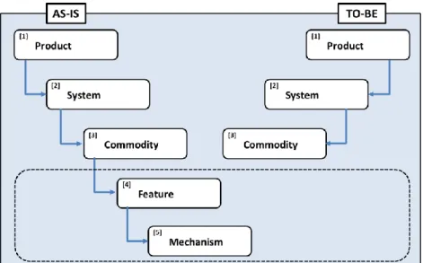
A model-based (physics-based) model is hard to construct for a complex system to collect degradation data (Brotherton et al, 2000; Bolander et al, 2010). However, the data-driven model seems appropriate for only assembly level failure data. The research focuses on the components at assembly level because there are no available data at an individual component level. The logical relationship of the mechanism, component/commodity system/assembly and product is shown in Figure 1-2. The purpose of Figure 1-2 signifies the AS-IS current state analysis of historical data to determine nature and level of degradation mechanisms, feature of the component with failure, the component/commodity of the system/module and the system of the product/engine. The TO-BE side implies the proposed component failure and RUL prediction which relate to the engine and components. Damage is assumed
7
to be present in the component, hence, the use of reliability model and no need to show features and damage mechanisms.
Figure 1-2: Relationship process for existing and proposed scenario
The mechanism and feature phases are assumed and built-in in the degradation model for the component. While the AS-IS depicts the traditional maintenance strategy, the TO-BE relates to the predictive maintenance strategy. In the current practice discussed in chapter 4, the method for analysing component degradation consumes time, reduces the reporting time of spare parts inventory, extends engine downtime and increases manpower cost. There is a difficulty in evaluating documented degradation mechanisms. It is hard to decide when to scrap the entire components in an assembly. In the current practice, it can be difficult to know the expected number of components to be rejected within an assembly until a traditional maintenance assessment is conducted. However, in addressing this challenge, a prognostication approach known as a predictive maintenance strategy is recommended (Rausand and Høyland, 2004). The predictive strategy uses historical and current health data to estimate impending rejections for scheduled maintenance. This predictive strategy is referred to as prognostics and health management in condition-based maintenance.
8
1.3 Research questions
The research questions are derived from the motivation of the research and problem definition. The research questions reflecting the information in Section 1.1 include:
i. How do we identify, analyse and derive relevant degradation information from service history data sets for the prediction of the remaining useful life a component in an assembly?
ii. How do we evaluate and fuse the identified degradation variables and parameters from disparate sources to assess through-life performance using assembly level data to predict the remaining useful life of a component?
iii. How do we validate the developed framework of through-life performance model systematically for component degradation and remaining useful life prediction?
1.4 Research sponsors
Through-life Engineering Service (TES) Centre
The Through-life Engineering Services (TES) Centre is an Engineering, Physical, Science, and Research Council (EPSRC) Centre for Innovative Manufacturing. The centre is a £15M National Centre which include a £5.7M from EPSRC – grant number EP/I033246/1. The centre conducts world-class research to support manufacturing industries in the UK. The TES centre supports UK manufacturing sector with through-life engineering services for customers worldwide. The centre delivers high value products with predictability, availability and reliability through companies and their supply chain to improve competitiveness with lowest life-cycle costs. The centre (TES Centre, 2013) creates advance and innovative capabilities to: develop technology and processes to improve design and manufacturing for engineering services; reduce whole life cost of high-value products; improve knowledge on interaction amongst electronics, mechanical and software systems; create innovative and potentially disruptive strategies; and
9
expand regenerative manufacturing. The centre aims to conduct state-of-the-art research in maintenance and installation costs reduction, and advise using robotics systems for maintenance, repair and overhaul.
Rolls Royce (RR)
Rolls Royce is a distinguished engineering organisation and worldwide provider of state-of-the-art power and propulsion systems. The systems are manufactured for use on land, at sea and in the skies. The company’s operating domain covers aerospace (civil and military), nuclear, energy, marine and services. The company provides maintenance, after sales support, delivery and engine disposal to shipping, logistics, military and airlines for passenger carriers. The company operates a business-to-business model of operation. Examples of engines for civil aviation wide body and narrow body aircraft are Trent 700, 900, 1000 and XWB.
The company offers performance-based business model to ensure engines have prolonged life through innovative and effective maintenance, repair and overhaul, thereby improving durable design. Its business performance model delivers power-by-the-hour showing the essence of circular economy for resources efficiency and long-term sustainability, by selling cycles of flight service. This business performance model is used for civil aerospace wide and narrow body aircraft – Boeing 787 and Airbus A380. The company offers material sustainability strategy through its diverse manufacturing facilities to support spare parts management. Components are manufactured from about 20,000 tons of super alloys metal materials annually. The company reprocesses 90% -100% of titanium and nickel super alloys captured from machining gas turbine materials (Kiser et al, 2016). The innovative design and advanced service operations improve performance and reduce whole life-cycle costs (Rolls Royce, 2005). The company’s overhaul activities begin on-wing in-service diagnostics using advanced engine health management practice to identify anomalies. This can lead to further investigation of the engine being taken off the aircraft – off-wing for further overhaul activities including repair of components and replacement.
10
Rolls Royce an Original Equipment Manufacturer (OEM) has a matchless understanding and knowhow in repair and overhaul of gas turbine engines. These repair and overhaul are conducted in facilities around the world, which include Ansty, Bristol, Montreal, Oakland California and Oberursel in Germany (Rolls Royce, 2017).
1.5 Thesis structure
This chapter discusses the research context, motivation and scope, problem definition and research questions. Figure 1-3 illustrates the layout of this Thesis.
11
Chapter 2 reviews the literature with respect to remaining useful life prediction methods, techniques and methodologies. This chapter focuses on the specific methodologies; techniques and methods applied in achieving the aim of the research. Other areas covered in this chapter include through-life engineering services, degradation mechanisms, taxonomy and ontology, timeline visualisation of events, an overview of maintenance strategies, renewal theory, parameter estimation, performance metrics and remaining useful life models. Chapter 3 highlights the aim, objectives and a systematic approach to the scientific research methods applied. Chapter 3 further discusses the methodology, rationales and the scientific research approaches used in this Thesis. The adopted methodology implemented in this research is presented. Chapter 4 examines and analyses the current (AS-IS) practice on the level and nature of component degradation from a traditional maintenance perspective. Chapter 4 discusses the relationship of the product, system, commodity, feature and mechanism about the service history and current health degradation information. In this context, taxonomies were automatically extracted using terminology recognition and relationship extraction techniques to show a hierarchy of relationship representation and the number of components, features and mechanisms.
Chapter 5 presents an extension from the investigation of the degradation mechanisms taxonomy to events taxonomy to generate an ontology of events relating to multiple engines and multiple overhauls states. The investigation and analysis show the multiple maintenance cycles on a timeline for events visualisation. Furthermore, overhaul sequence and activities are outlined.
Chapter 6 demonstrates prognostic through-life modelling based on knowledge acquired in chapters 4 and 5 to create a generic framework for predicting the remaining useful life of components. The framework outlines the through-life performance of component degradation based on the renewal theory from an actuarial perspective. The pre-processed data were used to estimate the parameters of the Weibull function. The application of renewal theory was
12
introduced in the model to calculate the number of R-Cube at each overhaul state. The through-life model distinctively and accurately forecasts the number of R-Cube components for the next overhaul transition state. The state transition approach utilises the expected R-Cube outcome at the failure time onto the next overhaul. A model evaluation using a back-fitting algorithm was produced using a performance metric to calculate the deviation accuracy of the initial parameters. The application of a cost variable was used to determine the time to replace the entire component assembly. The remaining useful life of the components is predicted using RUL methodologies, techniques and methods discussed in chapter 2. The through-life performance approach reflects on the research objectives and contributions to knowledge stated in Sections 3.1 and 9.2.1. Chapter 7 discusses results of the framework developed in chapter 6 and the scenarios of a case study. Data-driven methodology, statistical technique and the Weibull method are implemented to analytically model the through-life performance of a set of components in an assembly. The case study scenarios include single stage, single stage repair replacement and multiple stage. The presented results of the case study scenarios are described.
Chapter 8 describes the validation and verification conducted with experts including analysis of the outcomes.
Chapter 9 presents discussions on the various chapters of this Thesis, contribution to knowledge and limitations, implementation challenges, future works and conclusions.
1.6 Summary
This chapter gives an overview of the research problem. The introduction presents the research background and highlights the relevant areas of focus in this Thesis. This chapter includes the motivation, rationale and scope, the research questions, research sponsors and overall structure of the Thesis sections. The next chapter presents the literature review, a research gap and relevant topics essential for this applied research project.
13
2 LITERATURE REVIEW
This chapter presents a detailed literature review regarding through-life engineering service, maintenance strategies, ontology and taxonomy, timeline visualisation, parameter estimation, modelling, performance metric, degradation and remaining useful life prediction methodologies. In this thesis, the remaining useful life prediction methods and techniques are categorised into methodologies and further discussed in detail. The merits and demerits of the prediction methodologies are highlighted as well as the challenges of current prediction models. Section 2.1 describes the methodology for the literature review. Section 2.2 deals with Through-life Engineering Service. Section 2.3 gives an overview of maintenance strategies. Section 2.4 described taxonomy and ontology. Section 2.5 discusses condition-based maintenance. Section 2.7 relates to visualisation. Section 2.8 gives evidence of parameter estimation. Section 2.9 highlights modelling approach. Section 2.10 describes application of renewal theory. Section 2.11 relates to performance metric. Section 2.12 discusses renewal of repaired components. Section 2.13 give a detail discussion of remaining useful life approaches. Section 2.14 highlights the research gaps. Section 2.15 summarises chapter 2.
2.1 Methodology
This research focuses on developing a technique for through-life performance modelling to predict the remaining useful life of a component within an assembly. Figure 2-1 presents the methodology for this chapter. The study is intended to capture the state-of-the-art research on remaining useful life prediction. Whilst conducting this research, the keywords were searched and discussed briefly are “through-life engineering service”, “maintenance strategies”, “ontology and taxonomy”, “timeline visualisation”, “parameter estimation”, “modelling”, “performance metric”, and “degradation”. The aforementioned keywords were used to establish the context of the research. However, the main aspect is the remaining useful life prediction approach was relevant and a thorough literature
14
search and discussion were conducted in detail, and statistics about the outcomes presented in Figures 2-2, 2-3 and 2-4.
Figure 2-1 Literature review methodology
Content analysis is used as a research method to capture the current practice. The outcome is expected to support a proposed technique for remaining useful life prediction. Marasco (2008) note that content analysis relates to (a) defining the sources and procedures for searching of documents that should be analysed and (b) describing the categories instrumental to the classification of the documents collected. The extensive literature search covers articles from the years 2005 to 2015 as of 26th January 2016, (see Figure 2-3). The survey of literature was carried out using Scopus database and a total of 1,875 documents were analysed based on the remaining useful life keywords. Figure 2-2 shows a search result analysed and scaled down to centre on the pertinent documents.
15
Figure 2-2 The number of literatures on RUL per year
Figure 2-3 shows the document counts of the authors, where Goebel, K., is the most prolific author in the field of remaining useful life predictions followed by Zerhounni, N., and Lall, P.
16
However, the literature type and the literature presented as a pie chart show a variety of the documents. This pie chart shows conference papers are mostly written followed by peer reviewed journal papers (see Figure 2-4A). A note indicates a document from the Canadian Journal of Civil Engineering.
Figure 2-4: Comparative literature by (A) type and (B) subject area
Figure 2-4B shows that the engineering discipline engages mostly on this topic of remaining useful life research closely followed by the computer science field. These documents were reviewed and classified in line with their contents. The outcomes of the findings from the literature review inspired a provision of semi-structured interview questions for industry interaction (see chapter 4).
2.2 Through-life Engineering Services
Through-life Engineering Services (TES) concept is defined as technical services that are necessary to guarantee the required and predictable performance of an engineering system throughout its expected operational life with the optimum whole life cost (Roy et al, 2013). TES coordinates and provides the research capability for the creation of high-value engineering systems based on design and manufacturing. TES aims to improve the reliability, spare parts availability, maintainability and safety of products to deliver the lowest possible whole life cycle cost. TES assists in the transfer of best practices between different industrial sectors and extending the life of industrial goods (Roy et al, 2013).
17
However, TES can be suitable for all manufactured industrial product-service systems.
Through-life Engineering Services has themes that allow for maintenance, repair and overhaul functions to align with the operations strategy of an organisation. TES facilitates correct application of technology supported by the efficient use of service knowledge. Significant benefits obtained from accurate life prediction can improve MRO decision making (Farnsworth et al, 2015; Uhlmann et al, 2015). The simulation tools are used to adapt procedures, modular maintenance systems, and informed disposal decisions that facilitate the prediction of trustworthy life expectancy. Increasing the application of advanced information technology, Product Lifecycle Management (PLM) processes for distribution and collaboration, condition monitoring, and prognosis can significantly improve product availability, thereby reducing cost and downtime (Okoh et al, 2014). Degradation management is an aspect of TES and the maintenance of autonomous systems as well as the development of capabilities in a collaborative environment to enhance the lifespan of components. The concept of cost engineering provides a performance-based service approach and whole-life cost model, which applies to the full system maintenance and service delivery systems to deliver effective business solutions. The uncertainty modelling and simulation techniques based on technological and trade uncertainties are used to improve component/product designs. The concepts above and methodologies when supported by obsolescence management, service network for capability assessment and cost estimation have the potential to improve the design function greatly. As a result, there will be an improvement in quality, reliability, availability and safety while yielding feedback to manufacturers (Roy et al, 2013; Chopra et al, 2016; Morant et al, 2016; Zhang and Pham, 2016).
2.3 Degradation Mechanisms
The characterisation of in-service degradation mechanisms analysis requires knowledge of the properties of the titanium and nickel based super alloys which are candidate materials for gas turbine engines. The materials degrade over time
18
at the high temperature associated with aircraft operations. The candidate material is the primary component manufactured for gas turbine engines. The degradation mechanisms which are predominant in metallic components are corrosion, deformation, fracture and wear (Zhu et al, 2013; Imran et al, 2014; Prozhega et al, 2014; Giourntas et al, 2016). There is a need to curtail component’s failure and a timely awareness of failure mechanism is essential for maintenance decisions with regards to through-life engineering services (Farnsworth et al, 2015; Redding et al, 2015; Uhlmann et al, 2015; Van Dongen, 2015). The types of degradation mechanisms are further discussed in and applicable to chapter 4. Furthermore, the degradation processes discussed are hard to predict, hence, supporting the need for this research.
2.3.1 Corrosion
Corrosion is a chemical deterioration process resulting from an electrical or biological reaction, which includes oxidation and sulphidation (see Figure 2-5). Methods to measure corrosion rates include, for example, an electrochemical technique, which shows the speed at which reinforced steels are corroding and help identify degraded areas (Soleymani and Ismail, 2004; Prozhega et al, 2014).
Figure 2-5 Metal discs showing corrosion on the surface
2.3.2 Deformation
Deformation changes the geometry or shape of a component such as shrinking, stretching, bending, and twisting. They have cumulative effects upon strain in a component due to an applied force (Norman, 2013; Zhu et al, 2013). Aspects of
19
deformation are time dependent and time independent mechanisms. In Creep deformation, the component gradually accumulates over time with the presence of high temperature and thermal cycles stress until the product fails (Norman, 2013; Zhu et al, 2013; Giourntas et al, 2016). Monte Carlo-based uncertainty technique, optical measurement systems, digital image correlation, the intensity method and phase shift method are often used for deformation measure (Gåsvik et al, 2014).
2.3.3 Fracture
Fracture is separation of a material by means of cracking or disintegration which makes a component incapable of performing its designed functions. It can occur as a result of chemical effects, shock and/or stress. This fracture failure mechanism occurs via loading which is independent of time (Norman, 2013). A slow change (creep) in structure can lead to fracture whereby the presence of crack can grow rapidly in steels and aluminium alloys as shown in Figure 2-6. Johnson and Cook (1985) indicate that fracture increases slightly as strain rate increases in copper, iron and steel using a fracture model, pressure - strain ratio is critical as well as temperature and stress rate.
Figure 2-6 Bearing external ring failure and inner ring failure with fracture (Source: (Medjaher et al, 2012)) (see appendix A for permission)
2.3.4 Wear
Wear – material loss over a period of time resulting from component use. The estimation of wear (or resistance to wear) can be achieved by implementing the weighting method to fix and measure wear. This wear failure mechanism can be calculated by weighting the component before and after use. The variables to
20
consider include speed, friction co-efficient, surface finish/texture, surface hardness, load, the number of cycles, and time are all critical in estimating adhesion wear of metallic engine components (e.g. nickel based super alloys, brass, aluminium and steel) (Ameen et al, 2011; Zhu et al, 2013; Imran et al, 2014). This research submits that deformation, fracture, wear and corrosion can be measured to ascertain through-life perspectives of a component using a variety of methods relative to prognostics models.
2.4 Taxonomy and Ontology
Taxonomy involves non-similar words and broadly is a vocabulary, but a collection of controlled terms organised into hierarchical structure. The taxonomy extracted from a service maintenance repository for different degradation mechanisms include for example “fracture” with synonyms as crack, tear, and break (Uschold and Gruninger, 2004).
Ontology (Gruber, 1993) serves as a problem solving tool of the conceptualisation of entities (Maedche and Volz, 2001). The concepts and relations between them are used to reason and describe a domain knowledge. Ontology knowledge repository which may use taxonomy in a controlled vocabulary, but expressed in an ontology representation language by employing a grammar that shows something meaningful for a domain of interest. Ontology can be described as a recognised nomenclature and classification of the different word types, properties, and interrelationships, which are present in a specific domain, for example, aerospace. The ontology hierarchical arrangement represents a more natural means of information management in a unique domain. The content in the ontology aids the identification and retrieval of relevant keywords from sentences and reports based on subject, verb and object approach. The application and analysis are conducted in chapter 4 of this Thesis.
2.5 Overview of maintenance strategies
Brown and Sondalini (2016) describe maintenance as the management, control, execution and quality of activities to reasonably ensure design levels of
21
availability and performance of assets meet business objectives. Maintenance is conducted using different strategies as presented in Figure 2-7. The maintenance strategies are listed and classified as a taxonomy with a focus on the selected strategies in the blue boxes (Rausand and Høyland, 2004).
Figure 2-7 A proposed taxonomy of maintenance strategies Corrective maintenance
Rausand and Høyland (2004) argue that corrective maintenance relates to repair tasks carried out after an asset has failed. Historically, the last sixty year since the second World War, the world has transformed the maintenance perspective (Brown and Sondalini, 2016). Corrective maintenance was the only viable option for engineers to fix or replace breakdown equipment. Though, corrective maintenance is still very much in use currently such as electric light bulbs. Corrective maintenance aims to bring equipment back to its functioning state (Rausand and Høyland, 2004).
Preventive maintenance
Rausand and Høyland (2004) describe preventive maintenance as a planned maintenance performed when an item is functioning properly to prevent future
22
failures. The preventive maintenance strategy consists of age-based, calendar/clock-based, opportunity-based and condition-based. Age-based specifies the age of an asset measuring time in operation such as the number of take-offs and landings for an aircraft, while clock-based maintenance tasks are conducted at specific calendar times; a block replacement policy (Rausand and Høyland, 2004). In the special case, where the downtime due to maintenance and the downtime due to repair/replacement is negligible, the calendar-based and the age-based maintenance policies become alike (Tang, 2012). In practice, clock-based is easier to schedule compared to age-based. The former is less proficient than the latter from random maintenance scheduling before renewal (Tang, 2012). Opportunity maintenance – preventive maintenance applicable for multi-item systems where maintenance tasks on other items give an opportunity for carrying out maintenance, which were not the cause of opportunity (Rausand and Høyland, 2004). Pintelon and Gelders (1992) opine opportunity maintenance replaces equipment components, which are yet to fail based on available maintenance resources. This opportunity maintenance improves system availability and reduce production loss by reducing operations excellence and increases production efficiency (Borges, 2015). Condition-Based describes measurements of one or more condition variables of an asset, which are initiated when a condition variable passes a threshold (Rausand and Høyland, 2004). Rausand and Høyland (2004) state that condition-based is also known predictive maintenance, which determines the state of an in-service system to predict future maintenance when the need arises. The concept assesses the health condition of an equipment continuously and extrapolates to a predefined failure threshold (Camci and Chinnam, 2010; Eker et al, 2011). The condition-based maintenance is one aspect of focus in this research with further discussions presented in the next section.
2.6 Predictive maintenance
In the context of this Thesis, predictive maintenance and traditional/conventional maintenance are discussed. However, a predictive maintenance culture adopted
23
for on-time decision making assesses the health of a component in-service before system failure. The predictive maintenance minimises system life cycle losses and life cycle costs. This predictive maintenance strategy can save cost over a traditional maintenance. It provides appropriate scheduling for a traditional maintenance to prevent unpredicted system failures. The advantages of predictive maintenance include optimisation of spare parts management, enhanced system lifetime, guarantees safety and availability of the system. The predictive maintenance strategy reduces the risk of tragic events, remove unexpected outage and minimise the cost of gas turbine components (Di Maio et al, 2011). Figure 2-8 shows a categorisation and the relationship of predictive maintenance as diagnostics and prognostics.
Figure 2-8: A taxonomy of condition-based maintenance
2.6.1 Component degradation diagnostics
Diagnostics is a process for checking faults and the healthy state of sub-systems and units in an operating environmental condition with the aid of sensors. During maintenance, inspection is required to identify damage on components and provide information on the current performance status (Banjevic, 2009).
24
Boyce (2006) analyses the turbine section of the gas turbine, which houses the first-stage vanes and the last-stage blades. In the turbine section, the effect of corrosion on the first-stage vanes of the gas turbine is a severe and preliminary inspection for cracks or bowings can be conducted. However, this Thesis focuses on the first-stage vanes. The first-stage of vanes are typically superficially inspected using a Borescope for gaining entrance into the turbine through the combustion chamber areas or by removing the inspection plates. Degradation mechanisms are also called fouling mechanisms, which affect the turbine section are described in Table 2-1.
25
Table 2-1 Failure mechanisms in vanes (Boyce, 2006)
No Failure Mechanisms General Description First Stage Vanes 1 Nozzle vane bowing Reduction in the passage area
High temperature Improper cooling
High wheel space temperature
The vanes can suffer from hot corrosion
Thermal Barrier Coating (TBC) Spallation 2 Burnt nozzle vane Uneven combustion creates various hot
spots, which lead to melting of the vanes
Trailing edge melted Damage to vane platforms is
usually due to improper cooling
3 Incomplete
combustion or excess fuel
During start-up, the fuel is not
combusted and collects in the stationary vanes, which acts as flame holders Ensures that the control system has a
rate of acceleration and shutdown mode
Vanes totally melted
4 Hot corrosion Type I (over 1500oF)
An active form of oxidation, caused by the reaction of the Sodium (Na) in the air of fluid
Sulphur, which is usually in the fluid and oxygen
Intergranular attack Sulphide particles,
A denuded zone of base metal
Damage to the leading edge Erosion of the TBC attack on
the base coating
5 Hot corrosion Type II (between 1100oF to 1450oF)
Caused by low melting eutectic compounds resulting from the contamination of Sodium sulphate and some of the alloy constituents such as nickel and cobalt
Layered type of corrosion
Not applicable
6 Hot gas erosion-oxidation
Caused by small solids in the air or the fuel
With common combustor pattern Excessive engine gas temperature
(EGT) pattern
Failure of the TBC on the nozzle vane or platforms Not even around
circumference
7 Blade tip rubs Due to subtle tip clearance
High metal temperatures in the blades
Not Applicable
8 Blade fretting erosion Fretting in the dovetails/fir trees is caused by the rocking action of the blades
Peaking turbines are highly susceptible to this problem
Several attacks on trailing edge and leading edge On the concave side of the
airfoil
9 Blade and wheel rupture failure
This failure occurs in high temperature and highly loaded blades (highly stressed) and disks
Disk failure can be catastrophic Caused by inadequate cooling due to
blockage cooling passages
Creep distortion usually at trailing edge
10 Foreign object damage (FOD) Domestic object damage (DOD)
FOD occurs from materials coming from an external source to the gas turbine DOD occurs from failure of internal
components
Most damage from this point forward
11 Low Cycle Fatigue (LCF)
Turbine disks
First stage turbine suffering from low steady state stress due to thermos-mechanical fatigue problem Peaking turbines more susceptible
Cracks in the Vanes Single vane segments suffer
less than multiple vane segments
12 High Cycle Fatigue (HCF)
Can Occur in any blades or vanes due to the blade resonance frequency being excited
Occurs in blades where there are no tip or mid-span shrouds
Not applicable to most designs