Laser Metrology and Machine Performance XI
CMM Sensor Evaluation Method with
Machine Error Exclusion
B. Boeckmans
1, M. Zhang
1,2, F. Welkenhuyzen
1, W. Dewulf
3,
J.-P. Kruth
11
KU Leuven, Department of Mechanical Engineering, Celestijnenlaan
300, B-3001 Leuven, Belgium
,
[email protected]
2
College of Mech. Eng. and Applied Electronics Tech., Beijing
University of Technology, Beijing 100124, China
3
KU Leuven, Campus Groep T, A. Vesaliusstraat 13, B-3000 Leuven,
Belgium
Abstract
Sensors for coordinate measuring machines (CMM) are nowadays assessed within a measurement system, i.e. while mounted onto a CMM. This means that the accuracy or uncertainty of the sensor or probe is not really identified on its own, but may be influenced by the accuracy or uncertainty of the CMM on which the accuracy testing is done. Determining the accuracy and repeatability of a sensor, apart from the machines uncertainty, could yield useful information in several cases. For instance sensor damage can be ruled out after a machine crash if the sensor could be tested apart from the machines uncertainty. Also testing a new sensor on an older machine sometimes poses a problem, as the sensors inaccuracy can vanish in the total uncertainty of the measuring system due to a high CMM uncertainty.
This paper describes the current standardised and accepted methods for evaluating the integration of a CMM sensor in the environment of the machine. Furthermore tests are described to exclude the CMM uncertainty as best as possible to come to an assessment that characterises the sole sensor uncertainty. This is done through smart positioning of the reference tool, using another reference tool in combination with another measurement strategy or using extra equipment to exclude CMM errors. Preliminary results are presented and discussed.
1
Introduction
Today’s industry needs faster measurement techniques to assess their products fully, taking into account the higher complexity and increasing number of features to be verified. Many measurement techniques offer advantages towards speed, e.g. continuous tactile scanning probes [1], laser scanning probes [2] or computed tomography [3]. The increase of measurement speed usually goes
Laser Metrology and Machine Performance XI
hand in hand with an increase in uncertainty. This can be put in relation to the higher demands on the mechanical structure and software of faster measurement equipment, the higher amount of influencing factors and the insufficient development of those new measuring techniques. One of the ways to overcome this issue is to apply sensor fusion of different techniques [4].
Non-contact sensing techniques are in different stages of maturity. Computed tomography is gaining interest and is being developed for dimensional metrology at a rapid pace [3], but still has some teething problems that have to be overcome. Laser scanning has already evolved to the extent that it can be called mature as a technique that can contribute or compete with tactile measurements on a coordinate measuring machine (CMM). One of the advantages of laser scanning is that it can be implemented in a similar environment (i.e. on the same measuring machine) as the widely used and accepted tactile probes. This also provides the possibility to use the laser scanner probe in combination with a tactile probe, using the same machine coordinate system (MCS) and thus the same machine uncertainty [5, 6].
To compare different probing techniques on a standard CMM, several issues have to be taken into account. Firstly, the influential factors for contact and non-contact probing techniques differ greatly [7]. Secondly, the techniques are inherently different in the way they interact with surface roughness. Tactile probes mechanically filter rough surfaces while non-contact probes assess it fully up to the structural resolution. Also, surface reflectivity does not affect tactile probing whereas it may severely disturb laser scanning. Thirdly the sensors have different stand-off distances, which will cause different sections of a CMM to be used.
Tests exist to identify the measurement accuracy or uncertainty of CMM probes such as the previously mentioned tactile probes and laser scanner probes [8, 9, 10, 11]. The latter can be assessed according to the standard for the accuracy assessment of optical CMM probes (ISO 10360-8.2 [12]).
Yet the methods described in those standards determine not only the uncertainty for each sensor but also includes some machine errors and errors linked to the sensor-machine integration. They do not allow in-depth comparison between different probes. The evaluation according to these standards is thus closely interlinked with the accuracy of the used CMM equipment.
This paper proposes an assessment method for CMM probes trying to counter and eliminate most of the inherent CMM errors, mainly axis-related issues such as positional accuracy, straightness and squareness of the machine axes.
2
Geometric error components on CMMs
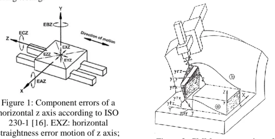
The incidence of geometrical errors of a Cartesian CMM on its measurements is quite evident and well documented in literature. The six error components of each axis show influences on the other axes (Figure 1). The effects on the entire machine are unmistakable as all axes are linked together combining all errors in one error map (Figure 2). These errors can however be measured and mapped
Laser Metrology and Machine Performance XI
through a variety of techniques [13] using laser interferometers, auto-collimators, electronic levels and/or self-calibration measurements in which the own measuring system of the CMM is used to measure reference objects, like ball plates, and assess the 21 geometrical errors of a CMM [14].
The interlinked CMM error components disturb the assessment of the accuracy of the measurement probe being investigated on the CMM. The probe is being attached in a mechanical CMM frame, usually with 3+2 degrees of freedom. In Section 3.1 standardised techniques are discussed. The result here is a method of total error assessment, including both the machine and the sensor used for this evaluation (MPEE) [15]. Section 3.2 aims to eliminate the errors
discussed here to the best possible extent, to be able to assess the accuracy of the probe on its own (MPEP) [15]. This separation gives the opportunity to
investigate the sensor more individually and independently of the machine used during testing.
Figure 1: Component errors of a horizontal z axis according to ISO
230-1 [16]. EXZ: horizontal straightness error motion of z axis;
EYZ: vertical straightness error motion of z axis; EZZ: positioning
error; EAZ, EBZ and ECZ: pitch, yaw and roll error motion of z axis.
Figure 2: CMM representation of geometric error components of the y
axis and their influence on the total measurement volume [17].
3
Evaluation methods
This section consists of two main parts. Section 3.1 describes the standardised machine tests to evaluate the performance of a measuring machine including the sensor that is being used. Section 3.2 consists of three subsections, where every proposal works out one type of machine error exclusion or compensation. Section 3.2.1 uses a similar setup and artefact as the one from Section 3.1 but with a specifically chosen sensing orientation to eliminate most of the CMM error components. Section 3.2.2 uses another reference artefact with elevated spheres to eliminate more machine errors using an adapted machine axis use. Section 3.2.3 proposes the addition of a laser interferometer to measure the axis movement of the setup discussed in Section 3.2.1.
Laser Metrology and Machine Performance XI
The use of a calibrated length between two sphere centres simplifies the assessment of the uncertainty or MPE value of a system. This is the reason why either a sphere beam or the reference artefact with elevated spheres is used.
3.1 Including CMM error components - total error assessment
As mentioned in Section 1 many methods are at hand to identify the measurement accuracy for optical CMM probes such as a laser scanner. The obtained results can then be used to prove conformance with ISO 14253: GPS – Inspection by measurement of workpieces and measuring equipment [8, 9]. An-other important document and tool is the ISO GUM Evaluation of measurement data – Guide to the expression of uncertainty in measurement [11].
For laser line scanners a standard exists, namely ISO 10360-8.2 [12]. This standard deals with the accuracy assessment of optical CMM probes. Since the document describes a methodology with wide applicability, extra tests can and have to be conducted to include the wide range of sensing parameters, such as laser intensity, scan velocity, point cloud density, location in the field of view, etc. Several developments in this field have been reported in literature, such as dedicated performance evaluation tests [7] and 3D positional uncertainty studies [18].
ISO 10360-8.2 proposes the use of a solid structure with spherical features which are compatible with the measurement sensor. The tool should have calibrated centre distances. As depicted in Figure 3 this entity, in most cases a sphere beam, should be positioned along all axes and machine volume diagonals to verify the accuracy of the system as a whole. For the feature measurements of the spheres it is important to capture the measurement data spread over the entire feature as proposed in ISO 10360-1 [10]. Results regarding tests for laser scanners have been reported [19].
Figure 3: Sphere beam alignment for CMM sensor assessment according to ISO 10360-8.2 [12].
The downside of this procedure however is the fact that the entire measurement system is observed. If the machine error is of the same order of magnitude as the sensors inaccuracy, it will be hard to distinguish the one from the other. For instance if you wish to assess the accuracy of a laser scanner with a certain MPEP value on a CMM with an MPEE statement as the one in (Eq. 1)
the use of 1m length sphere beam might hinder the partition between CMM accuracy and sensor accuracy (Eq. 2). This problem manifests itself even more
Laser Metrology and Machine Performance XI
when a state-of-the-art laser scanner with a low MPEP value is tested on a
machine with a higher uncertainty. The inaccuracy of the laser scanner is drowned by the CMM errors when conducting a sphere beam test. This is mainly the case if the MPEProbe would be considerably small with respect to the
other terms in the total equation for the MPEE,System value, shown in Eq. 2.
MPEE,CMM = A(µm) + B(µm/m) ∙ L(m) (Eq. 1)
MPEE,System = MPEProbe + MPEE,CMM = MPEP + A + B ∙ L (Eq. 2)
3.2 Probe Accuracy assessment
3.2.1 Excluding CMM error components through positioning
An initial step towards CMM error exclusion is quite evident. The artefact has to be positioned in a way that as few as possible of the CMM errors are included in the measurement. An example would be to place the reference tool along one machine axis. Figure 4 shows a feasible setup for a sphere beam on a CMM, in this case the artefact is along the x axis of the measurement equipment.
Figure 4: Setup of the sphere beam along the x axis of a CMM.
The advantage of locating the artefact along one CMM axis is twofold. Firstly, the geometrical error components of the machine are restricted from a total of 21 error components to only six, namely the ones linked to that one axis (Figure 1), being the x axis in the setup of Figure 4. Secondly, the errors on that one axis movement may be less influenced by other characteristics (second order influences): e.g. no mass displacement along the y axis that may cause variable torque and bending around the x axis (EAX and EAY errors). Tracing the influence of the error components of that one axis (x axis) on the total uncertainty will be more straightforward and thus more feasible to distinguish or compensate. The exact uncertainty of the axis is most often not known. Only the maximum specification is given by the manufacturer as stated in Eq. 1. Eq. 2 for instance expresses the total measurement error of a CMM equipped with a measuring probe.
The CMM error components can be determined in advance and then taken into account. Since A and B (Eq. 1) are only declaring a maximum specification an overestimation of the machine’s influence most often is made. Therefore an
Laser Metrology and Machine Performance XI
additional step should be taken: either avoidance of this overestimation or knowing the actual error components more in detail than just the notation of Eq. 1. The proposed steps are discussed respectively in Section 3.2.2 and Section 3.2.3.
3.2.2 Additional CMM error exclusion through measurement procedure adaptation
Avoiding the aforementioned overestimation of the MPEE,CMM can be realized
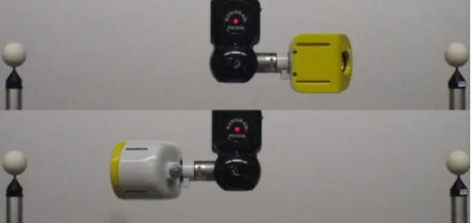
through using a restricted measuring volume. Eq. 1 proves that lowering the CMM traveling distance L, slackens the B-term of Eq. 1 and Eq. 2. Usually this traveling distance is equal to the measured feature size or length. As most CMMs are equipped with a rotary head with two degrees of freedom, it is however possible to rotate the head and probe over 180° in order to assess two reference features quite far apart using little of the CMM’s measurement volume. Figure 5 (top and bottom) presents a configuration in which two spheres, located left and right of the probe head, are measured subsequently with the rotary head first oriented right for measuring the right sphere (top figure) and then rotated 180° to measure the left sphere (bottom figure). Notice that in this case the distance between the two spheres is such that they both can be measured with the CMM head in the same position: i.e. the CMM traveling distance is zero. Comparing the measured distance between the two spheres with the calibrated and known inter-sphere distance allows assessing the probe accuracy without influence of the accuracy of the CMM itself.
Figure 5: Configuration set for probe assessment with the elevated spheres artefact.
The drawback of this procedure is that inaccuracies in the probe calibration procedure might still spoil the measurement. This calibration should now involve multiple probe orientations and uses a larger part of the measuring volume during calibration. The positioning and the choice of the calibration tools have to be thought out well with respect to the position of the assessed artefact. Another option would be to ascertain the sensor standoff distance with respect to its rotation point more accurately than through the calibration on the CMM.
Laser Metrology and Machine Performance XI
3.2.3 Additional CMM error exclusion through real-time positional error determination
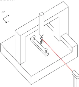
The intention of knowing the detailed CMM positional accuracy is to overrule the CMM readout of one axis entirely. In Section 3.2.1 for instance, the readout of the x axis can be shifted to a laser interferometer. Figure 6 shows a schematic overview of a laser interferometry setup to overrule the axis along which the sphere beam is positioned.
Figure 6: Schematic overview of a laser interferometry setup to measure the sensor head position.
The sensor readout (planar information) can be superimposed on the laser interferometer output of the x position of the joint point on the schematic overview (Figure 6) instead of the CMM output of its x axis linear scale. This way the only moving axis of the CMM is measured by a technique which is far more accurate.
Also for the setup in Section 3.2.2 the measurement movement can be tracked this way. Yet if the probe calibration is done on the CMM the damage has already been done by the CMM errors spoiling a precise calibration.
4
Preliminary results
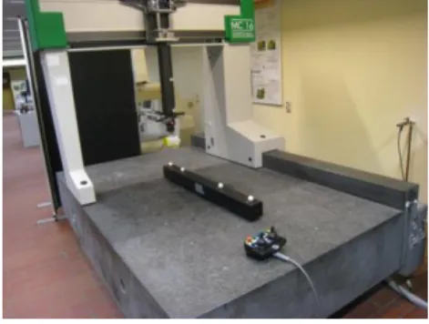
A first set of tests has been conducted on a Coord3 CMM with an MPE as stated in Eq. 3. The CMM was equipped with a Nikon Metrology LC60Dx laser scanner (MPEP = 9µm). A KoBa sphere beam (depicted in Figure 4) and a
self-made elevated sphere artefact incorporating 2 optically cooperative KoBa spheres (depicted in Figure 5) were the reference artefacts.
Laser Metrology and Machine Performance XI
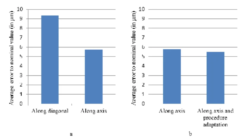
The measurement errors to the nominal value of the sphere centre distances of the reference artefacts are discussed below. Figure 7a represents the average error to the nominal value of the measurements on setups using the KoBa sphere beam. Figure 7b displays similar results for the elevated sphere artefact.
Figure 7: Error to nominal value (in µm) for a) sphere beam measurements and b) elevated sphere artefact measurements.
The trend visible in Figure 7a proves that the total uncertainty drops when positioning along one axis (Section 3.2.1) in comparison to using the volume diagonal as feature direction (Section 3.1). Most likely the systematic error lowers enough to be visible in the measurement results. The number of measurements was so far restricted to 3 or 5 measurements and thus solid conclusions cannot yet be formed.
Figure 7b (elevated spheres setup) displays no trend, which might be caused by the use of probe calibration on a different location on the machine. Further experiments have to be performed to exclude the error still visible in the results of the setup proposed in Section 3.2.2.
5
Conclusions
This paper described CMM sensor assessment in two major components: full system evaluation (sensor and machine environment combined) and evaluation of the sensor uncertainty on its own.
Firstly, the state-of-the-art was discussed, referring to standardised documents. An important factor in the state-off-the-art assessment of sensors is that the inaccuracy of the CMM that equips the sensor is always included. Secondly, three methods of error avoidance in the CMM environment were addressed. Consecutively the positioning along an axis, the use of a different setup that allows the use of multiple sensor orientations and the combination with an extra more accurate measurement technology were described.
Laser Metrology and Machine Performance XI
The last section showed some preliminary results that will lead to further investigation of the proposed techniques.
Notice that those methods have been illustrated for an optical laser scanning probe, but may often be equally used for tactile probe assessment.
6
References
[1] Renishaw: http://resources.renishaw.com/en/details/technical-paper-sp25m--3873
[2] Van Gestel, N., Cuypers, S., Bleys, P., Kruth, J. (2007). A performance evaluation test for laser line scanners on CMMs. Proc. Of the
OPTIMESS2007 Workshop.
[3] Kruth, J., Bartscher, M., Carmignato, S., Schmitt, R., De Chiffre, L., and Weckenmann, A. (2011). Computed tomography for dimensional metrology. CIRP Annals - Manufacturing Technology, (60/2), 821-842. [4] Weckenmann, A., Jiang, X., Sommer, K.-D., Neuschaefer-Rube, U.,
Seewig, J., Shaw, L., Estler, T. (2009). Multisensor data fusion in dimensional Metrology, CIRP Annals - Manufacturing Technology, (58/2), 701-721.
[5] Zhao, H., Kruth, J., Boeckmans, B., Van Gestel, N., Bleys, P. (2012). Automated dimensional inspection planning using the combination of laser scanner and tactile probe. Measurement: Journal of the International Measurement Confederation, (45/5), 1057-1066.
[6] Igor, B., Van Gestel, N., Kruth, J., Bleys, P., Hodolič, J. (2011). Accuracy improvement of laser line scanning for feature measurements on CMM.
Optics and Lasers in Engineering, (49/11), 1274-1280.
[7] Van Gestel, N., Cuypers, S., Bleys, P., Kruth, J. (2009). A performance evaluation test for laser line scanners on CMMs. Optics and Lasers in Engineering, (47), 336-342.
[8] ISO 14253-1:1998. GPS – Inspection by measurement of workpieces and measuring equipment – Part 1: Decision rules for proving conformance or non-conformance with specifications.
[9] ISO 14253-2:2011. GPS – Inspection by measurement of workpieces and measuring equipment – Part 2: Guide to the estimation of uncertainty in GPS measurement, in calibration of measuring equipment and in product verification.
[10] ISO 10360-1:2000. Geometrical Product Specifications (GPS) – Accep-tance and reverification tests for coordinate measuring machines (CMM) – Part 1: Vocabulary.
[11] ISO, GUM, JCGM 100:2008: Evaluation of measurement data - Guide to the expression of uncertainty in measurement.
[12] ISO 10360-8.2:2012. Geometrical Product Specifications (GPS) - Accep-tance and reverification test for coordinate measuring machines (CMM) - Part 8: CMMs with optical distance sensors.
Laser Metrology and Machine Performance XI
[13] Schwenke, H et al. (2008). Geometric error measurement and compensa-tion of machines - An update. CIRP Annals - Manufacturing Technology, (57/2), 660-675.
[14] Kruth J.-P., Vanherck P., De Jonge L. (1994). Self-calibration method and software error correction for three dimensional coordinate measuring machines using artefact measurements. Measurement, (14), 157-167. [15] ISO 10360-2:2001. Geometrical Product Specifications (GPS) -
Accep-tance and reverification tests for coordinate measuring machines (CMM) - Part 2: CMMs used for measuring size
[16] ISO 230-1:2012. Test code for machine tools - Part 1: Geometric accuracy of machines operating under no-load or quasi-static conditions.
[17] Barakat, N. A., Elbestawi, M. A., Spence, A. D. (2000). Kinematic and geometric error compensation of a coordinate measuring machine.
International Journal of Machine Tools and Manufacture, (40), 833-850. [18] Bernard, A., Véron, M. (1999). Analysis and Validation of 3D Laser
Sensor Scanning Process. CIRP Annals – Manufacturing Technology, (48/1), 111-114.
[19] Boeckmans, B., Welkenhuyzen, F., Kruth, J. (2013). Accuracy verification of a laser line scanner probe. Laser Metrology and Machine Performance X, 279-288.
![Figure 3: Sphere beam alignment for CMM sensor assessment according to ISO 10360-8.2 [12]](https://thumb-us.123doks.com/thumbv2/123dok_us/9407482.2816945/4.892.187.552.610.757/figure-sphere-beam-alignment-cmm-sensor-assessment-according.webp)