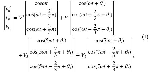
Novel PLL for power converters under unbalanced and distorted grid conditions
Full text
Figure
Related documents
Even then, the other reasons why lack of constitutional authority does not follow from Congress not enacting a statute may also suggest that Congress’s failure to enact a
study with the BAC contigs of the existing physical ( Mozo dopsis Genome Initiative (AGI; Arabidopsis Genome Ini- tiative 2000). 1999) and sequence ( Arabidopsis Genome Initia-.
[ 5 ] produced the same layer properties on the plate surface of 1050 aluminum alloy by using a plain cylindrical shoulder without pin in their research
Recent research offers evidence that integrated dual diagnosis treatments are effective, but basic interventions are rarely incorporated into the mental health programs in which
The model also includes leader ability to manage own emotions during change, leaders ability to appropriately express own emotions during change, follower perception of leader
The standalone solar photovoltaic and wind systems have been promoted around the globe on a comparatively larger scale. These independent systems cannot provide
A blocking enzyme-linked immunosorbent assay (ELISA) with a baculovirus-expressed structural protein was developed for the detection of antibodies to foot-and-mouth disease virus
The regression formulation estimated more one–dimensional nonparametric functions than the MNL formulation did from the same amount of data — four times more for the simulated data
