Original citation:
Bowyer, Jack, Hsiao, Victoria, Wong, Wilson W. and Bates, Declan. (2017) Mechanistic
modelling of a recombinase-based two-input temporal logic gate. Engineering Biology, 1 (1).
pp. 40-50.
Permanent WRAP URL:
http://wrap.warwick.ac.uk/93838
Copyright and reuse:
The Warwick Research Archive Portal (WRAP) makes this work of researchers of the
University of Warwick available open access under the following conditions.
This article is made available under the Creative Commons Attribution 3.0 International
license (CC BY 3.0) and may be reused according to the conditions of the license. For more
details see:
http://creativecommons.org/licenses/by/3.0/
A note on versions:
The version presented in WRAP is the published version, or, version of record, and may be
cited as it appears here.
Mechanistic modelling of a
recombinase-based two-input temporal
logic gate
ISSN 2398-6182
Received on 28th February 2017 Revised on 17th May 2017 Accepted on 26th May 2017 doi: 10.1049/enb.2017.0006 www.ietdl.org
Jack E. Bowyer
1, Victoria Hsiao
2, *, Wilson W. Wong
3, Declan G. Bates
1✉
1
Warwick Integrative Synthetic Biology Centre, School of Engineering, University of Warwick, Coventry CV4 7AL, UK
2
Biology and Biological Engineering, California Institute of Technology, Pasadena, CA 91125, USA
3
Department of Biomedical Engineering, Boston University, Boston, MA 02215, USA
*
Current address: Amyris Inc., Emeryville, CA 94608, USA
✉E-mail: [email protected]
Abstract:Site-specific recombinases (SSRs) mediate efficient manipulation of DNA sequencesin vitroandin vivo. In particular, serine integrases have been identified as highly effective tools for facilitating DNA inversion, enabling the design of genetic switches that are capable of turning the expression of a gene of interest on or off in the presence of a SSR protein. The functional scope of such circuitry can be extended to biological Boolean logic operations by incorporating two or more distinct integrase inputs. To date, mathematical modelling investigations have captured the dynamical properties of integrase logic gate systems in a purely qualitative manner, and thus such models are of limited utility as tools in the design of novel circuitry. Here, the authors develop a detailed mechanistic model of a two-input temporal logic gate circuit that can detect and encode sequences of two-input events. Their model demonstrates quantitative agreement with time-course data on the dynamics of the temporal logic gate, and is shown to subsequently predict dynamical responses relating to a series of induction separation intervals. The model can also be used to infer functional variations between distinct integrase inputs, and to examine the effect of reversing the roles of each integrase on logic gate output.
1
Introduction
1.1 Engineering cellular memory using DNA recombination
Genetic switches form the basis of engineered cellular memory [1, 2]. Transcriptional memory devices have demonstrated effective performance across multiple cellular environments [3–5]. In particular, the characterisation of the genetic toggle switch in
Escherichia coli [6] triggered the advent of synthetic biology, demonstrating that user-defined functionality can be engineered in biological systems. Such circuits are highly orthogonal with regard to assembling multiplexed systems [7]; however, regulating gene expression in this manner also has limitations. These systems are volatile, relying on continuous consumption of cellular resources such as repressors in order to maintain states [8]. Given that genetic regulatory networks also vary significantly between distinct cellular environments, integration of such devices into a variety of organisms presents additional difficulties. Furthermore, the highly inducible and stable switching that cellular memory devices demand can be compromised by spontaneous switching events caused by the inherent stochasticity of gene regulation [9]. Consequently, research on the engineering of cellular memory in synthetic biology has become increasingly centred around site-specific recombinases (SSRs), which are capable of precise DNA manipulation both in vitro and in vivo [10]. This process, known as DNA recombination, facilitates inducible gene expression that is programmed into the cellular DNA. DNA-based systems are particularly promising for the engineering of cellular memory devices since they exploit a natural data storage material and have the added advantage of eliminating cell specificity requirements.
SSRs are classified as belonging to two groups: the tyrosine recombinases and the serine recombinases. The former have been shown to provide effective genetic switch mechanisms [11–13],
but their functionality is often dependent on cell-specific cofactors, as in the case oflintegrase [14]. This poses a similar problem to that of transcriptional systems with respect to deploying modules across multiple organisms. Tyrosine recombinase systems that are not dependent on host cofactors are bidirectional, and are, therefore, incapable of highly efficient switching since there can be no guarantee that an induced transition to a desired DNA state would be effectively maintained without unwanted transitioning back to the original state [15]. In contrast, serine recombinases do not require such cofactors and have been used effectively to perform highly efficient unidirectional gene assembly and modification [16]. This has led to the construction of a rewritable recombinase addressable data (RAD) module exhibiting passive information storage within a chromosome [9]. The RAD module
‘on’ switch requires only the presence of integrase, whereas the
‘off’ switch requires integrase in conjunction with excisionase, also referred to as a recombination directionality factor (RDF). Recombination events are, therefore, referred to as integration and excision according to the SSRs and attachment sites involved, and such events can take on several guises depending on the initial composition of the genetic sequence and the associated attachment sites.
Two distinct DNA recombination mechanisms are known to mediate three distinct recombination events, referred to as inversion, insertion and deletion. The first mechanism exploits the inversion event (Fig. 1a). In this case, dimeric integrase binds to antiparallel attB and attP sites located on the same DNA sequence, causing double-stranded breaks in each. That is, integrase alone is sufficient to mediate a primary inversion event. Exposed ends in the genetic sequence then bind the opposite ends of the intermediate fragment, resulting in an inverted section of DNA flanked by newly formed composite attachment sites, termed attL and attR. A successive inversion event occurs when RDF molecules bind to the extant attL and attR DNA:integrase synaptic complexes. This re-establishes attB and attP by dismantling the
Engineering Biology
attL and attR sites, allowing for the exposed ends of the intermediate fragment to adopt their original orientation.
The second mechanism exploits the deletion and insertion events between attachment sites on the same DNA sequence (Fig.1b). In this case, the attachment sites are identical to that of Fig.1awith the exception that the orientations of attB and attP are subtly different, i.e. they are parallel as opposed to antiparallel. Binding of dimeric integrase to attachment sites adopting this alternative orientation causes the same double-stranded breaks, but the exposed ends of the intermediate nucleotide sequence are now bound together to form a small loop of DNA that is deleted from the original sequence. The exposed ends of the original sequence are also bound together to form a single attR site. RDF binding re-inserts the deleted loop of DNA and reforms attB and attP. Hence, this alternative orientation of attachment sites does not facilitate the same inversion of the intermediate genetic fragment depicted in Fig.1a, but instead deletes the fragment entirely with the potential of insertion via an appropriate RDF.
We investigate inversion- and deletion-based DNA recombination systems, since the action of these mechanisms is localised to a single DNA strand, hence offering greater simplicity compared with the manipulation across disparate genetic sources associated with insertion. The concentrations of integrase and excisionase in the system dictate the efficiency of the switching between distinct DNA states. We have previously developed a mechanistic mathematical model that provides quantitative replication of the dynamics of the RAD module in response to such experimental
conditions. Accurate characterisation of RAD module switching efficiency is crucial to the deployment of the genetic switch as a component of higher-level systems. The ‘reset’ functions facilitated by excisionase-mediated inversions or insertions provide useful transitioning back to original system states; however, the specific concentrations of integrase and excisionase required to do this are not easily determined [9]. Operational regimes that control system output as a function of excisionase induction are able to overcome this difficulty, but also require constant induction of integrase expression which is undesirable in many applications [17]. By analysing the criteria required to mediate both highly efficient integration and excisionin silico, we have identified a set of optimal system inputs. For example, our model exhibits higher efficiency associated with integration compared with excision, and also reveals the operative cycles required to realise the desired digital response [18,19].
1.2 Biological Boolean logic
Specific arrangements of attachment site pairs directly influence the operational characteristics of the genetic switch and higher-order circuitry that utilises multiplexed switches. The genetic switches mediated by SSRs are the precursors to synthetic biological logic gates. Both tyrosine and serine recombination mechanisms are capable of eliciting Boolean logic gate functionality within biological cells [17, 20–22]. By considering integrase as the system input, the RAD module (genetic switch) is initially set in its primary state, state 1, in the absence of integrase and then generates the new state, state 2, on induction (Fig. 2a). This provides inducible control over two distinct genetic outputs which is particularly valuable in regulating gene expression. There is, however, a maximum of two outputs that can be controlled in this manner given that the system has one integrase input specific to the relevant attachment sites on the DNA strand. Logic gate functions are dependent on two distinct binary inputs that are either‘on’(1) or‘off’(0) and, therefore, biological logic gates usually require at least two integrase inputs (Fig.2b). This requires two pairs of specific attachment sites corresponding to two distinct integrases; multiple identical pairs of attachment sites will be bound by the same integrase and would present the same switch mediated by a single integrase input. This also means that combining logic gates to create more sophisticated circuitry can only be achieved using orthogonal gates that employ distinct recombinase inputs [23], and hence the functional specifications of characterised recombinases will be crucial in the circuit design process. A recent study has demonstrated that recombinase-based
Fig. 1 Schematic diagram of DNA recombination mechanisms
aGenetic materialflanked by attB and attP is inverted through integration to form attL and attR. Excision restores attB and attP via a secondary inversion event
bAlternative orientations of attB and attP result in deletion of the intermediate genetic sequence which is inserted in the presence of RDF
In each case, integration gives rise to attL and attR, each formed of half of attB and attP
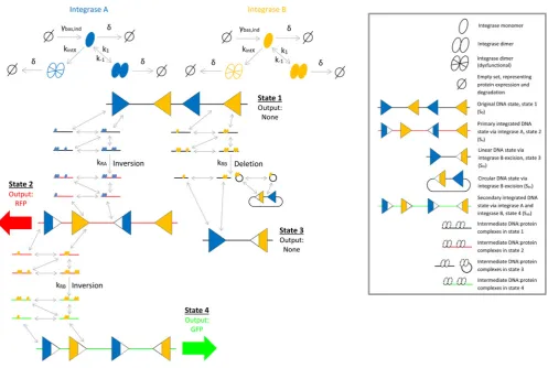
Fig. 2 Schematic diagrams of one-input and two-input serine-integrase-mediated synthetic circuitry
aOne-input recombinase-based genetic switch
bRecombinase-based two-input logic gate
cRecombinase-based two-input temporal logic gate
[image:3.595.80.251.51.419.2] [image:3.595.310.549.51.246.2]switches that can store 1 bit of information such as the RAD module are able to provide over 1 B of memory capacity when layered in the appropriate manner. This is made possible by the extensive characterisation of distinct integrases that do not exhibit the crosstalk that may potentially cause the gate to fail, and are, therefore, completely viable for use as system inputs [24].
The precise arrangement and orientation of distinct attachment sites are vital to realising the desired logic output. By positioning the attachment site pairs sequentially along the DNA strand in an antiparallel manner, the initial sequence of nucleotide bases will encode state 1 in the same way as a one-input switch. However, more distinct DNA states can be obtained via induction of each integrase input, integrase A and integrase B. Integrase A will mediate the inversion of the genetic sequence between its corresponding attB and attP sites and produce the encoded state 2; integrase B will mediate the equivalent reaction to produce state 3. Simultaneous induction of integrase A and integrase B results in the inversion of both corresponding genetic sequences which encode the final output, state 4. The same four distinct DNA states are achieved if the timing of the induction events is staggered, rather than simultaneous, since state 1 and state 2 both reach state 4 in the presence of the appropriate integrase. This dynamical behaviour defines a truth table for the standard two-input biological logic gate [Table 1(a)]. State transitioning is a unidirectional process unless excisionase-mediated reset functions are incorporated; however, this will invariably compromise the dynamical behaviour of the logic gate or toggle switch in question [9,19].
The most interesting distinction to be made between the biological logic gate and the idealised Boolean logic gate that it seeks to emulate is that the biological gate is able to encode up to four distinct states as opposed to a maximum of two states. That is, though the integrase inputs driving the biological gate occupy binary states, the outputs are four distinct genetic sequences each of which could potentially code for a different molecular product if engineered in the appropriate manner. Indeed, designing genetic sequences and attachment site pairs that produce desired gene expression only when the configuration reaches that of state 4 would encompass the AND gate function (i.e. state 1 = 0, state 2 = 0, state 3 = 0 and state 4 = 1). This might be particularly useful in cases where extra stringency on the control of gene expression is required. On the other hand, restricting the scope of biological output to one of two binary states may be viewed as prosaic in light of the potential variety of operations.
The biological logic gate has the capacity for even further functional advantages when considering the temporal induction of integrase inputs [25]. As previously described, sequential positioning of two distinct attachment site pairs will provide a maximum of four outputs due to staggered induction events giving rise to the same end state, but alternative initial arrangements are capable of providing additional information. For example, overlapping attachment sites has the ability to define integration
pathways culminating in two distinct end states, given the appropriate initial orientation of the attachment sites (Fig. 2c). Such circuit designs exploit the DNA inversion event by placing attachment sites in the intermediate genetic sequence between two corresponding attachment sites. This results in an inverted genetic sequence giving rise to a new DNA state as well as an inverted attachment site whose role in any subsequent integration events is altered and may potentially partake in either inversion or deletion.
Positioning the attachment site pairs in an overlapping arrangement on the DNA strand with one antiparallel pair (corresponding to integrase A) and one parallel pair (corresponding to integrase B) presents a similar state 1 to that of the standard logic gate design. However, in this case integrase A will mediate the inversion of the genetic sequence between its corresponding attB and attP sites and produce the encoded state 2 comprised of both pairs of attachment sites in an antiparallel arrangement. Integrase B will, instead, mediate the deletion of the genetic sequence between its corresponding attachment sites to produce state 3, comprised of two disparate attachment sites. Induction of integrase B following integrase A will then transition state 2 to state 4 via a secondary inversion event due to the new antiparallel orientation of the corresponding attachment sites. Integrase A is unable to perform integration following induction of integrase B since there is no longer an appropriate pair of attachment sites to target and thus state 5 is identical to state 3. Hence, we have a temporal logic gate capable of deliveringfive outputs in response to two inputs [Table 1(b)]; however, this functionality is restricted to at least two of the five outputs being identical which, biologically, present the potential for inducible control over four molecular products, as is the case for the standard logic gate. Thus, though the number of distinct outputs has not increased, the temporal logic gate is able to infer both the order of induction events and the time between each event since staggered induction does not produce identical end states (Fig. 3). A temporal logic gate, therefore, has unique functional properties that make it highly suitable for synthetic biosensor applications.
An important factor to consider with respect to temporal logic gates is the time interval between induction events, since simultaneous induction of input integrases will likely result in a split end state whereby both state 4 and state 5 are accessed. Ideally, the appropriate induction will facilitate maximal transitioning to the desired DNA state, though the conditions required to achieve this are not obvious. Mathematical models can examine large arrays of performance criteria in order to determine optimal inputs and provide operational profiles that can inform the selection of the most suitable circuit designs based on the desired outputs.
2
Constructing a mechanistic model of the
temporal logic gate
[image:4.595.315.549.56.166.2]The model of [25] describes the transitioning of the temporal logic gate from the original DNA state (S0) to each of the three end
Table 1a The standard logic gate provides the typical four outputs as DNA states that could be engineered to deliver any logic function
A B O
0 0 state 1
1 0 state 2
0 1 state 3
1 1 state 4
Fig. 3 Schematic diagrams summarising biological logic outputs
aStandard logic gate transitions through four distinct states with the end state accessed regardless of the timing of integrase inputs
[image:4.595.41.287.76.135.2]bTemporal logic gate transitions throughfive states with certain states only accessible via specific induction time schedules
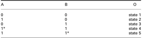
Table 1b The temporal logic gate also provides four distinct outputs since at least two of the states are identical; stars denote which integrase input is induced first
A B O
0 0 state 1
1 0 state 2
0 1 state 3
1* 1 state 4
[image:4.595.41.288.178.245.2]states (Sa, Sb and Sab) via three corresponding rate constants describing inversion mediated by TP901-1 (integrase A), and both deletion and inversion mediated by Bxb1 (integrase B). We replace these all-encompassing parameters with a mechanistic integration reaction structure, in which inversion and deletion events are initiated by the binding of one integrase dimer at each of the associated attachment sites (four integrase monomers in total) and are strictly unidirectional [26, 27] (Fig. 4). We account for dimerisation of both monomeric SSRs, allowing for both monomeric and dimeric integrase binding to DNA attachment sites. This process is widely supported in the experimental literature on DNA recombination [28–31]. Thus, four distinct intermediate DNA:protein complexes can potentially be formed in facilitating recombination via this combination of monomeric and dimeric integrase binding. These complexes are represented by the small colour-coded DNA strands in Fig. 4. We also include the formation of a dysfunctional dimer by both integrases, which is subject to the same degradation as its functional counterpart; this was shown to significantly improve thefit of model simulations to experimental data in our previous study [18, 19]. Deletion gives rise to two distinct genetic products, the remaining linear sequence of the target DNA and the excised circular DNA loop, and hence we account for two disparate Sb states, Sbl (linear) and Sbc
(circular). We refer to the DNA statesS0,Sa,Sbl andSabas state 1, state 2, state 3 and state 4, respectively, noting that this system is void of a fifth DNA state due to the ‘dead end’ state, state 3, which is unable to transition to any subsequent state. We do not account for Sbc as a system state since it is separate from the original DNA sequence that is intended to be manipulated.
Model validation against experimental data for an in vivo
recombinase-based system presents a number of factors that require careful consideration. Cellular recombination in vivo
is dependent on the expression and degradation of recombinase proteins over time, thus contributing two additional parameters (g, d) to the model. In the absence of induction, in vivosystem exhibits background expression of SSRs, commonly resulting in basal system output. Thus, we include model parameters describing both basal (gbas) and induced (gind) expressions of the two integrases, allowing for non-zero model output when simulating experiments void of integrase induction.
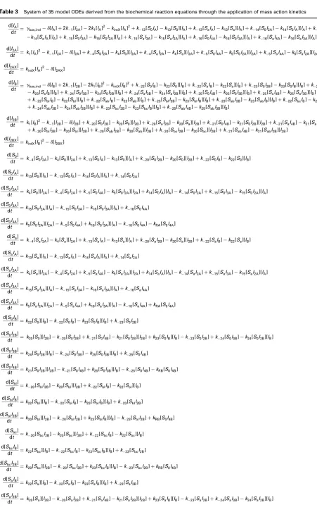
Our mechanistic model is constructed through the application of mass action kinetics to the biochemical equations (Table 2, the Appendix) arising from the reaction network in Fig. 4. This produces a system of 35 ordinary differential equations (ODEs) that are solved numerically to provide a deterministic model output (Table3, the Appendix).
The formation of intermediate DNA:protein complexes, due to monomeric and dimeric integrase binding, in our mechanistic model gives rise to multiple state variables associated with the two DNA states of interest, state 2 (Sa) and state 4 (Sab). Summing all the ODEs describing the dynamics of state variables associated with the same DNA state of interest provides the total register of the system in those states (SaTand SabT). Hence, model outputs are determined through the numerical solutions to the following ODEs:
dSaT
dt =kRAS0I4A−kRBSaI4B (1)
dSabT
dt =kRBSaI4B (2)
where kRA andkRBare the parameters describing inversion and/or deletion mediated by integrases A and B, respectively, S0I4A Fig. 4 Schematic diagram of the mechanistic two-input logic gate reaction network
Sequence of DNA:protein interactions facilitating integration, taken from [18], enables the system to transition from the original DNA state (state 1) to the three genetically differentiated DNA states (state 2, state 3 and state 4). Expression and degradation of integrases A and B are denoted bygbas, indandd, respectively. Intermediate DNA:protein complexes with red and
[image:5.595.51.549.51.385.2]represents four integrase A monomers bound to DNA in state 1 and
SaI4Brepresents four integrase B monomers bound to DNA in state 2. The model also consists of 32 parameters that are optimised through comparisons of the solutions to (1) and (2) with our experimental data.
3
Results and discussion
3.1 Model validation via global optimisation
Global optimisation techniques are designed to locate optimal parameter sets globally within often very large parameter spaces, avoiding local minima. One such method, the genetic algorithm (GA), is a particularly powerful global optimisation tool and is exploited regularly in biological model parameter inference [32, 33]. The GA converges to the global minimum within the allocated parameter space by evolving an initial population of randomly generated solutions over a large number of generations (see Section 5).
Induction of integrase B prior to integrase A causes transition to the unwanted deleted DNA state, state 3, and, therefore, we optimise our model against experimental data regarding induction of integrase A prior to integrase B only (see Section 5 for our experimental procedure). Our data was generated as part of the research presented in [25], but was not presented in that publication. It is comprised of both redfluorescent protein (RFP) and green fluorescent protein (GFP) levels (state 2 and state 4, respectively) under eight distinct experimental conditions. First, fluorescence is recorded for no induction of either integrase and, second,fluorescence is recorded for induction of integrase A only. A further six experimental procedures record fluorescence for induction of integrase B at increasing time intervals,dT, such that dT =0, . . ., 5 h following induction of integrase A. We assume that RFP and GFP provide a direct readout of the DNA state of the system that equates to the concentration levels required to parameterise our model. Since the observed fluorescence has no physical dimension, the raw data for state 2 and state 4 are converted to percentages of the maximumfluorescence expression level recorded across all experiments to enable mathematical comparisons. This establishes the percentage fluorescence output data required to infer the parameters in our model. Given that we are using a deterministic model to simulate recombination efficiencies within a single cell, we overcome uncertainty regarding physical quantities of DNA by allocating an initial DNA concentration (state 1) of 1, hence all model outputs are bounded within a solution space of [0, 1]. Once a numerical output has been computed, it is divided by the maximum numerical output across all simulations and multiplied by 100 in order to establish the same percentage of maximum expression captured by our converted data. Hence, model outputs are subject to the same conversion applied to the experimental data, establishing percentage changes in observed fluorescence output for varying time intervals between the induction of integrases A and B.
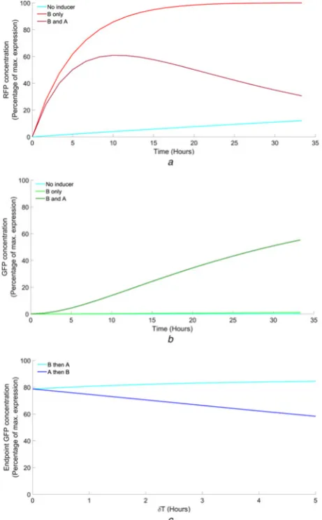
The optimised mechanistic model is able to capture the observed system dynamics for both state 2 (Fig.5a) and state 4 (Fig.5b). The model is initially simulated with the parameter describing basal expression of integrases A and B (gbas) simultaneously in order to generate non-zero no-inducer model outputs. Following basal simulations, the model is simulated with the parameter describing induced expression of integrases A and B (gind), but for integrase A only. Finally, the model is simulated with this induced expression parameter for integrases A and B simultaneously. The expression of fluorescent protein is greatest in state 2 for the induction of integrase A only. This is expected since the system is able to transition from state 1 to state 2 without integrase B induction causing significant competing transition to state 3. The system is able to maintain the transition to this state over time since further transitioning to state 4 is also minimal in the absence of integrase induction; transitioning to state 3 and state 4 is only possible in this case due to basal expression of integrase B. The optimised model simulation corresponding to this case presents the
greatest error observed across all six datasets, specifically with respect to the initial evolution of the response. The sigmoidal expression profile captured by this dataset is very difficult to emulate given our description of protein expression via constant parameters, and may instead require time-dependent protein expression to improve this fit. In contrast, the simultaneous induction of both integrases results in decreased fluorescence output in state 2. There is a small increase initially due to the state 2:state 3 split; however, state 2 cannot be maintained since integrase B induction is able to transition this transient state to state 4. Fluorescence is relatively low in state 4 for the induction of integrase A only. This is expected since transition from state 1 to state 4, in the absence of integrase B induction, is only possible due to the basal expression of integrase B. Fluorescence increases for the simultaneous induction of both integrases, but it does not reach a similarly high level to that of state 2 for the induction of integrase A only. This is due to the fact that the transition to state 3 and state 4 occurs simultaneously and hence neither state can be maintained at maximal levels. Increased fluorescence in state 4 is thus dependent on the delay between the inductions of the two integrases.
The optimal parameter set identified by the GA implies that integrase A operates on a slower time scale to that of integrase
Fig. 5 Datafitting and model prediction results
a Optimised responses of our mechanistic model against three state 2 time-course datasets
b Optimised responses of our mechanistic model against three state 4 time-course datasets
cModel predictions of the transitioning to state 4 in response to different induction separation intervals (A only, A and Bfits included fromb)
Circles depict experimental data; solid lines depict optimal model outputs (A only and
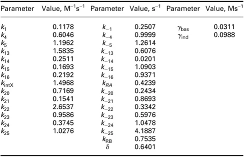
[image:6.595.318.545.54.429.2]B. Although the parameters describing integrase A-mediated DNA binding interactions (k+4,...,+16) and those describing integrase B-mediated DNA binding interactions (k+20,...,+25) all take optimal values in the interval [10−2, 101], the parameter describing the rate of recombination mediated by integrase B,kRB, is ∼77% greater than that of integrase A, kRA (Table 4, the Appendix). These are the two key parameters in generating the numerical solutions to (1) and (2) that comprise our model simulations and hence it appears that the rate of inversion/deletion mediated by integrase B is greater than that of integrase A in producing the dynamical behaviour captured by our experimental data. This implies that the action of integrase B is naturally faster than that of integrase A and may, therefore, be more useful as a component in the design of synthetic biological circuitry. Note that we have assumed the parameters describing protein binding interactions (k+1,kintX) are identical for each of the two integrases, just as the protein expression and degradation parameters. This minimises the overall number of model parameters, increasing the transferability of the model, and facilitates the inference of functional distinctions between the two integrase inputs as described above. Further examination of potential protein binding distinctions is possible for future studies at the cost of increasing the number of model parameters. The optimal parameter set is used to generate all plots in Fig.5, as well as all subsequent plots.
After training our model using the datasets in Figs. 5a and b, we used our optimised mechanistic model to predict a set of experimental data that was excluded from the training set. Optimised model predictions align with experimental data for increasing integrase induction delays (dT =1, . . ., 5) (Fig. 5c). As the delay between the inductions of integrases A and B increases, the time afforded to the maintenance of state 2 also increases. There is, therefore, a greater concentration of state 2 than state 1 when integrase B is eventually induced, and hence transition to state 4 is increased by virtue of integrase B-mediated inversion. Consequently, the transition to state 3 is decreased due to the decrease in concentration of state 1. Additionally, we validated our model by predicting endpoint GFP concentrations relating to both A then B temporal response data and an entirely separate dataset regarding B then A temporal responses. The endpoint response of the system as a function of the integrase induction separation interval dT is shown in Fig. 6. Optimal endpoint percentage model outputs as a function of dT align closely with that of the experimental data, providing further evidence of the model’s predictive capability. Fig.6also supports the notion that the efficiency of recombination induction via integrase B must be superior to that of integrase A since identical efficiencies would be expected to result in a 50:50 split for dT=0. This inequality in integrase-mediated inversion was previously observed in [25], but no mechanistic comparisons had been performed at that time. Consequently, it remains to experimentally examine functional differences between distinct integrases as these properties may allow for specific logic operations dependent on the pair of integrases selected, the
arrangement of the associated attachment sites and the specific roles each integrase input is assigned in the circuit.
3.2 Reversing the roles of integrase inputs
By allowing integrase B to occupy the role of integrase A andvice versa, we are able to investigate the effect of input reversal on the output of the temporal logic gate in silico using our optimised mechanistic model. This involves swapping the optimal parameter values corresponding to reactions mediated by integrase A with the equivalent optimal parameter values corresponding to reactions mediated by integrase B. That is, our previous ‘A then B’inputs are reversed in order to examine‘B then A’simulations. We simulate the same dynamical responses captured by our experimental data (Fig.7).
The effect of reversing integrase inputs on state 2, for the induction of integrase B only, results in an increased response time that results in faster transitioning to maximal RFP concentration (Fig. 7a). Induction of both integrases (dT=0) results in a dynamical response that exhibits a significant increase in transient RFP concentration compared with the original inputs. The expected sequestration of RFP concentration can be observed; however, it is unable to reach zero on the same timescale as the original input data. These simulations demonstrate the increased
Fig. 6 Endpoint GFP concentration results
A then B GFP percentage concentration endpoint predictions from Fig.5cplotted as a function ofdT(dT=0, . . ., 5; light blue plot line). Equivalent predictions of B then A temporal responses are depicted by the dark blue plot line. Model simulations generated using our optimal parameter set. Data generated as part of the research presented in [25]
Fig. 7 Model simulations of reversed integrase inputs
aOptimised model simulations of state 2 RFP concentration using reversed integrase inputs (No inducer, B only, B and A (dT=0))
bOptimised model simulations of state 4 GFP concentration using reversed integrase inputs (No inducer, B only, B and A (dT=0))
cB then A GFP percentage concentration endpoint simulations plotted as a function of
[image:7.595.314.545.320.693.2] [image:7.595.44.282.605.730.2]speed of the reactions mediated by integrase B since this transient state is expressed to a greater level before sequestration via the slower action of integrase A. Input reversal also has a significant impact on the expression of state 4 (Fig. 7b). Although the induction of integrase B only causes increased transition to state 2, the relatively slower action of integrase A results in negligible GFP concentration. However, simultaneous induction of both integrases (dT=0) causes a significant increase in concentration on the same timescale as the original inputs, thus demonstrating that the action of the slowest integrase in the input pair is rate limiting in the overall dynamical response of the temporal logic gate. This increase in concentration is likely due to the increased concentration of state 2 caused by integrase B which can be transitioned to state 4 via integrase A.
Induction separation intervals provide further evidence of the increased concentration achieved by reversing the integrase inputs (Fig. 7c). Here, the endpoint responses as a function of dT
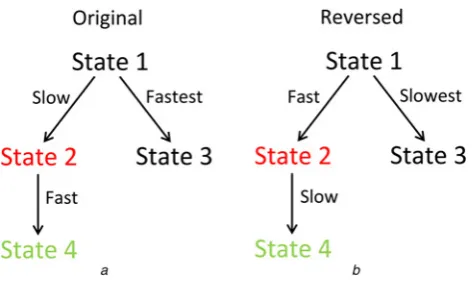
confirm that the expected 50% endpoint concentration fordT=0 is shifted significantly toward the concentration of state 4 and the expression of GFP (∼80%). This highlights the potential benefit of employing the more efficient integrase in the original role of integrase A, given the decreased transitioning to the unwanted state 3 that this provides. The endpoint concentrations plotted in Fig. 7c are taken from outputs simulated over an increased timescale in order to obtain steady-state levels that are not reached on the original timescale. As such, the increased efficiency of the circuit to transition to state 4 requires more time, and hence it is likely that a suitable trade-off between response time and efficiency will be required for optimal performance. The speeds at which the system is able to transition to each distinct DNA state for both input assignments are summarised in Fig.8.
3.3 Higher-order logic circuits
The natural progression of this work is to consider the functional scope of more sophisticated logic gates and higher-level computing devices such as adders, subtracters and decoders. These devices implement multiple switches and logic gates and, therefore, present ideal platforms for extending our modelling investigations. One potential device is a 2–4 decoder, a foundational circuit topology that can form the basis of many other circuits. A 2–4 decoder takes two specific inputs and returns one of four distinct outputs. We have demonstrated how this can be achieved by the temporal logic gate; however, it can also be realised through standard logic functions with increased numbers of attachment site pairs. Two possible architectures have been proposed for the decoder circuit design, one based on tyrosine recombination and one based on serine recombination. Both employ three pairs of specific attachment sites, but they employ just two distinct SSR inputs; one recombinase specific to two of
the three pairs of sites and one recombinase specific to the remaining pair of sites. The tyrosine decoder is purely excision based and is referred to as a Boolean logic and arithmetic through DNA excision platform (BLADE) [34]. The serine decoder is purely inversion based and exploits the recombinase binding interactions that have formed the focus of the research presented in our previous study. Constructing two models of the same system that are distinguished by their recombinase mediation mechanisms will allow us to examine the comparative advantages and disadvantages concerning the choice of these systems to suit various applications.
4
Conclusions
We have developed the first mechanistic mathematical model of a synthetic two-input temporal logic gate using previously validated models of in vitro DNA recombination reactions. Our model was validated against a series of time-course datasets, demonstrating quantitative replication of in vivo datasets relating to the induction of none, one or both integrases, and accurate prediction of the response of the logic gate to inputs separated byfive different induction separation intervals. Both our modelling investigation and our experimental data provide evidence of functional distinctions between the two integrase inputs, suggesting that integrase B, Bxb1, operates more efficiently than integrase A, TP901-1 (∼1.8-fold faster). Experimental data for other distinct serine integrases would allow us to develop a lookup table of logic functions dependent on the choice and assignment of inputs. The effect of reversing the roles of the two integrases was subsequently shown to elicit a more rapid response time as well as significantly greater GFP expression in state 4. Mechanistic models, therefore, have the potential to reveal functional nuances that might exist between other characterised integrases and hence inform further experimental verification. These results could, therefore, also have important implications in the design of higher-order logic circuitry when considering the ideal pairs of integrase inputs to select in order to realise the desired system output. Future work will extend our modelling investigations to higher-order logic circuits, namely 2–4 decoders in mammalian cells for potential therapeutic applications.
5
Materials and methods
5.1 Experimental procedure
The experimental system for the temporal logic gate with Bxb1 and TP901-1 integrases was implemented in DH5a-Z1E. coli. The Bxb1 and TP901-1 integrases are on a high copy plasmid (available from the Addgene plasmid repository, ID 82351). The temporal logic gate with integrase binding targets was chromosomally integrated into the Phi80 site of the E. coligenome using conditional-replication, integration, and modular (CRIM) integration [35]. A plasmid version of the same logic gate is also available from Addgene (ID 82352).
M9CA media was prepared with 1 × M9 salts (Teknova, M1906) augmented with 100 mM NH4CL, 2 mM MGSO4, 0.01% casamino acids, 0.15μg/ml biotin and 1.5μM thiamine. About 0.2% glycerol was used as the sole carbon source and the entire solution was sterile-filtered (0.2μm). During the experiment, all media contained the antibiotics chloramphenicol (Sigma-Aldrich, Inc. (C0378); 50μg/ml) and kanamycin (Sigma-Aldrich, Inc. (K1876); 30μg/ml). L-arabinose, the inducer for TP901-1, was used at a concentration of 0.01% by volume, and anhydrous tetracycline (aTc), the inducer for Bxb1, was used a concentration of 200 ng/ml (450 nM). All experiments were performed with the aid of timed liquid handling by a Hamilton STARlet Liquid Handling Robot (Hamilton Company).
At the beginning of the experiment, the cells were diluted to optical density (OD) 0.06-0.1 into a 96-well matriplate (Brooks Automation, Inc., MGB096-1-2-LG-L) with 500μl total volume in
Fig. 8 State transition speeds associated with input assignment
aOriginal circuit exhibits a faster transition to state 4 following slower accumulation of state 2
[image:8.595.48.286.53.194.2]M9CA. Cultures were incubated at 37°C in a BioTek Synergy H1F plate reader with linear shaking (1096 cycles/minute) (BioTek Instruments, Inc.), and inducers were added at various dT time points by the Hamilton robot. OD andfluorescence measurements (superfolder-GFP ex488/em520, mKate2-RFP ex580/em610) were taken every 10 min. Each experimental condition was performed on the plate in triplicate.
5.2 Global optimisation
We employ a parallelised GA function in MATLAB on a high-performance computing cluster to perform global optimisation of the mechanistic model against our large experimental dataset. This enables us to run the GA with a large population size and over a larger number of generations within manageable time frames, and hence increases the likelihood of identifying the global optimum solution. We select a parameter space of [10−6, 103] for all model parameters subject to inference. This is sufficiently large in light of the lack of documented reactions rate constants available in the literature, whilst minimising the potential for excessively stiff model simulations that may cause the GA to fail. We run the GA over 1000 generations to maximise the likelihood of convergence, and hence identification of the global optimum solution within the parameter space. The error function is comprised of six components, each corresponding to the six datasets that we optimise the model against. Since each dataset captures percentage concentrations of varying magnitudes, an error function that computes mean absolute error consequently takes individual contributions of varying magnitudes which may skew the optimisation across all six datasets. Our error function instead computes normalised absolute error with respect to the range of each dataset
E= 1 rNI
2 21
i=1
|xNI2i −d2NIi| + 1 rNI
4 21
i=1
|xNI4i−dNI4i| +. . .
1
rA 2
21
i=1
|xA2i−dA2i| + 1 rA
4 21
i=1
|xA4i−dA4i| +. . .
1
rAB 2
21
i=1
|xAB2i −dAB2i | + 1 rAB
4 21
i=1
|xAB4i −d4ABi |
(3)
where E is the error and xi, di are the model outputs and data values at each of the 21 corresponding time points,ti, respectively. The superscripts NI, A and AB denote simulations and data corresponding to no inducer, induction of A only and inductions of A and B simultaneously, respectively. The subscripts 2 and 4 denote simulations and data corresponding to the DNA states of interest, state 2 (Sa) and state 4 (Sab), respectively. The range of data values, r, is calculated for each dataset such that
r=d21−d1, and is used to normalise each component of the error function.
6
Acknowledgments
This work was carried out with support from a bilateral funding award from BBSRC (BB/P011926/1) and NSF (#1614642).
7
References
1 Burrill, D., Silver, P.:‘Making cellular memories’,Cell, 2010,140, (1), pp. 13–18 2 Ma, K., Perli, S., Lu, T.:‘Foundations and emerging paradigms for computing in
living cells’,J. Mol. Biol., 2016,428, (5 Pt B), pp. 893–915
3 Kobayashi, H., Kaern, M., Araki, M.,et al.: ‘Programmable cells: interfacing natural and engineered gene networks’,Proc. Natl. Acad. Sci. USA, 2004,
101, (22), pp. 8414–8419
4 Becskei, A., Seraphin, B., Serrano, L.:‘Positive feedback in eukaryotic gene networks: cell differentiation by graded to binary response conversion’,EMBO J., 2001,20, (10), pp. 2528–2535
5 Kramer, B., Viretta, A., Daoud-El-Baba, M.,et al.:‘An engineered epigenetic transgene switch in mammalian cells’,Nat. Biotechnol., 2004,22, (7), pp. 867–870 6 Gardner, T., Cantor, C., Collins, J.:‘Construction of a genetic toggle switch in
Escherichia coli’,Nature, 2000,403, (6767), pp. 339–342
7 Stanton, B., Nielsen, A., Tamsir, A.,et al.: ‘Genomic mining of prokaryotic repressors for orthogonal logic gates’,Nat. Chem. Biol., 2014,10, (2), pp. 99–105 8 Ajo-Franklin, C., Drubin, D., Eskin, J., et al.:‘Rational design of memory in
eukaryotic cells’,Genes Dev., 2007,21, (18), pp. 2271–2276
9 Bonnet, J., Subsoontorn, P., Endy, D.:‘Rewritable digital data storage in live cells via engineered control of recombination directionality’,Proc. Natl. Acad. Sci. USA, 2012,109, (23), pp. 8884–8889
10 Grindley, N., Whiteson, K., Rice, P.:‘Mechanisms of site-specific recombination’,
Annu. Rev. Biochem., 2006,75, pp. 567–605
11 Buchholz, F., Ringrose, L., Angrand, P.,et al.:‘Different thermostabilities of FLP and Cre recombinases: implications for applied site-specific recombination’,
Nucleic Acids Res., 1996,24, (21), pp. 4256–4262
12 Kilby, N., Snaith, M., Murray, J.:‘Site-specific recombinases: tools for genome engineering’,Trends Genet., 1993,9, (12), pp. 413–421
13 Rossant, J., Nagy, A.:‘Genome engineering: the new mouse genetics’,Nat. Med., 1995,1, (16), pp. 592–594
14 Landy, A.: ‘The l integrase site-specific recombination pathway’,Microbiol. Spectr., 2015,3, (2), doi: 10.1128/microbiolspec.MDNA3-0051-2014 15 van Duyne, G.:‘A structural view of cre-loxp site-specific recombination’,Annu.
Rev. Biophys. Biomol. Struct., 2001,30, pp. 87–104
16 Colloms, S., Merrick, C., Olorunniji, F.,et al.:‘Rapid metabolic pathway assembly and modification using serine integrase site-specific recombination’,Nucleic Acids Res., 2014,42, (4), doi: 10.1093/nar/gkt1101
17 Bonnet, J., Yin, P., Ortiz, M.,et al.:‘Amplifying genetic logic gates’,Science, 2013,340, (6132), pp. 599–603
18 Bowyer, J., Zhao, J., Rosser, S.,et al.:‘Development and experimental validation of a mechanistic model of a recombinase-based temporal logic gate’. Proc. Int. Conf. IEEE EMBS, Milano, Italy, August 2015, pp. 945–948
19 Bowyer, J., Zhao, J., Subsoontorn, P.,et al.:‘Mechanistic modeling of a rewritable recombinase addressable data module’, IEEE Trans. Biomed. Circuits Syst., 2016,10, (6), pp. 1161–1170
20 Branda, C., Dymecki, S.:‘Talking about a revolution: the impact of site-specific recombinases on genetic analyses in mice’,Dev. Cell, 2004,6, (1), pp. 7–28 21 DuPage, M., Dooley, A., Jacks, T.: ‘Conditional mouse lung cancer models
using adenoviral or lentiviral delivery of Cre recombinase’,Nat. Protoc., 2009,
4, (7), pp. 1064–1072
22 Friedland, A., Lu, T., Wang, X.,et al.:‘Synthetic gene networks that count’,
Science, 2009,324, (5931), pp. 1199–1202
23 Fernandez-Rodriguez, J., Yang, L., Gorochowski, T., et al.: ‘Memory and combinatorial logic based on DNA inversions: dynamics and evolutionary stability’,ACS Synth. Biol., 2015,4, (12), pp. 1361–1372
24 Yang, L., Nielsen, A., Fernandez-Rodriguez, J.,et al.:‘Permanent genetic memory with >1 byte capacity’,Nat. Methods, 2014,11, (12), pp. 1261–1266
25 Hsiao, V., Hori, Y., Rothemund, P.,et al.:‘A population-based temporal logic gate for timing and recording chemical events’,Mol. Syst. Biol., 2016,12, (5), p. 869 26 Groth, A., Calos, M.:‘Phage integrases: biology and applications’,J. Mol. Biol.,
2004,335, (3), pp. 667–678
27 Olorunniji, F., Buck, D., Colloms, S., et al.: ‘Gated rotation mechanism of site-specific recombination by fC31 integrase’,Proc. Natl. Acad. Sci. USA, 2012,109, pp. 19661–19666
28 Fogg, P., Colloms, S., Rosser, S.,et al.:‘New applications for phage integrases’,
J. Mol. Biol., 2014,426, (15), pp. 2703–2716
29 Ghosh, P., Pannunzio, N., Hatfull, G.: ‘Synapsis in phage Bxb1 integration: selection mechanism for the correct pair of recombination sites’,J. Mol. Biol., 2005,349, (2), pp. 331–348
30 Ghosh, P., Bibb, L., Hatfull, G.: ‘Two-step site selection for serine-integrase-mediated excision: DNA-directed integrase conformation and central dinucleotide proofreading’, Proc. Natl. Acad. Sci. USA, 2008, 105, (9), pp. 3238–3243
31 Khaleel, T., Younger, E., McEwan, A.,et al.:‘A phage protein that bindsfC31 integrase to switch its directionality’,Mol. Microbiol., 2011,80, pp. 1450–1463 32 Chen, B.-S., Chen, P.-W.:‘GA-based design algorithms for the robust synthetic
genetic oscillators with prescribed amplitude, period and phase’,Gene Regul. Syst. Biol., 2010,4, pp. 35–52
33 Fernandez, M., Caballero, J., Fernandez, L.,et al.:‘Genetic algorithm optimization in drug design QSAR: Bayesian-regularized genetic neural networks (BRGNN) and genetic algorithm-optimized support vectors machines (GA-SVM)’, Mol. Divers., 2011,15, (1), pp. 269–289
34 Weinberg, B.H., Pham, N.T.H., Caraballo, L.D., et al.:‘Large-scale design of robust genetic circuits with multiple inputs and outputs for mammalian cells’,
Nat. Biotechnol., 2017,35, (5), pp. 453–462
35 Haldiman, A., Wanner, B.:‘Conditional-replication, integration, excision, and retrieval plasmid-host systems for gene structure-function studies of bacteria’,
J. Bacteriol., 2001,183, (21), pp. 6384–6393
8
Appendix
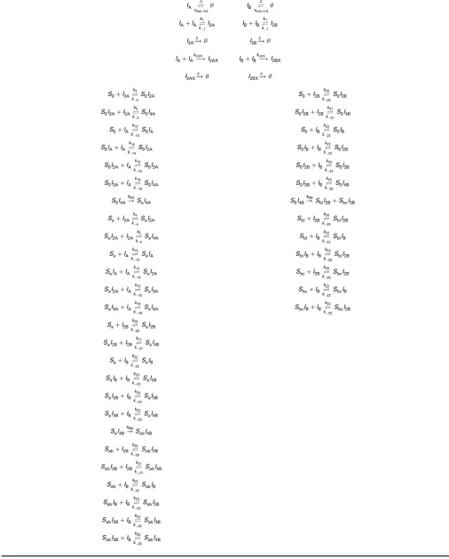
Table 2 Biochemical reaction equations comprising the temporal logic gate, as depicted in Fig.4
IA ⇋
d gbas, ind∅
IB ⇋
d gbas, ind∅
IA+IA⇋
k1 k−1
I2A IB+IB⇋
k1 k−1
I2B
I2A−
d
∅ I2B−
d
∅
IA+IA−
kintX
I2AX IB+IB−
kintX I2BX
I2AX−
d
∅ I2BX−
d
∅
S0+I2A⇋
k4 k−4
S0I2A S0+I2B ⇋
k20 k−20
S0I2B
S0I2A+I2A⇋
k5 k−5
S0I4A S0I2B+I2B ⇋
k21 k−21
S0I4B
S0+IA ⇋
k13 k−13
S0IA S0+IB ⇋
k22 k−22
S0IB
S0IA+IA ⇋
k14 k−14
S0I2A S0IB+IB ⇋
k23 k−23
S0I2B
S0I2A+IA ⇋
k15 k−15
S0I3A S0I2B+IB⇋
k24 k−24
S0I3B
S0I3A+IA ⇋
k16 k−16
S0I4A S0I3B+IB⇋
k25 k−25
S0I4B
S0I4A
kRA
SaI4A S0I4B
kRB
SblI2B+SbcI2B
Sa+I2A⇋
k4 k−4
SaI2A Sbl+I2B ⇋
k20 k−20
SblI2B
SaI2A+I2A⇋
k5 k−5
SaI4A Sbl+IB ⇋
k22 k−22
SblIB
Sa+IA ⇋
k13 k−13
SaIA SblIB+IB ⇋
k23 k−23
SblI2B
SaIA+IA ⇋
k14 k−14
SaI2A Sbc+I2B ⇋
k20 k−20
SbcI2B
SaI2A+IA ⇋
k15 k−15
SaI3A Sbc+IB ⇋
k22 k−22
SbcIB
SaI3A+IA ⇋
k16 k−16
SaI4A SbcIB+IB ⇋
k23 k−23
SbcI2B
Sa+I2B ⇋
k20 k−20
SaI2B
SaI2B+I2B ⇋
k21 k−21
SaI4B
Sa+IB ⇋
k22 k−22
SaIB
SaIB+IB ⇋
k23 k−23
SaI2B
SaI2B+IB ⇋
k24 k−24
SaI3B
SaI3B+IB ⇋
k25 k−25
SaI4B
SaI4B
kRB
SabI4B
Sab+I2B ⇋
k20 k−20
SabI2B
SabI2B+I2B ⇋
k21 k−21
SabI4B
Sab+IB ⇋
k22 k−22
SabIB
SabIB+IB ⇋
k23 k−23
SabI2B
SabI2B+IB ⇋
k24 k−24
SabI3B
SabI3B+IB ⇋
k25 k−25
SabI4B
Table 3 System of 35 model ODEs derived from the biochemical reaction equations through the application of mass action kinetics
d[IA]
dt =gbas,ind−d[IA]+2k−1[I2A]−2k1[IA]
2−k
intX[IA]2+k−13[S0IA]−k13[S0][IA]+k−13[SaIA]−k13[Sa][IA]+k−14[S0I2A]−k14[S0IA][IA]+k−14[SaI2A]
−k14[SaIA][IA]+k−15[S0I3A]−k15[S0I2A][IA]+k−15[SaI3A]−k15[SaI2A][IA]+k−16[S0I4A]−k16[S0I3A][IA]+k−16[SaI4A]−k16[SaI3A][IA]
d[I2A]
dt =k1[IA] 2−
k−1[I2A]−d[I2A]+k−4[S0I2A]−k4[S0][I2A]+k−4[SaI2A]−k4[Sa][I2A]+k−5[S0I4A]−k5[S0I2A][I2A]+k−5[SaI4A]−k5[SaI2A][I2A]
d[I2AX]
dt =kintX[IA]2−d[I2AX]
d[IB]
dt =gbas,ind−d[IB]+2k−1[I2B]−2k1[IB]
2−k
intX[IB]2+k−22[S0IB]−k22[S0][IB]+k−22[SaIB]−k22[Sa][IB]+k−23[S0I2B]−k23[S0IB][IB]+k−23[SaI2B]
−k23[SaIB][IB]+k−24[S0I3B]−k24[S0I2B][IB]+k−24[SaI3B]−k24[SaI2B][IB]+k−25[S0I4B]−k25[S0I3B][IB]+k−25[SaI4B]−k25[SaI3B][IB]
+k−22[SblIB]−k22[Sbl][IB]+k−22[SabIB]−k22[Sab][IB]+k−23[SblI2B]−k23[SblIB][IB]+k−23[SabI2B]−k23[SabIB][IB]+k−22[SbcIB]−k22[Sbc][IB]
+k−24[SabI3B]−k24[SabI2B][IB]+k−23[SbcI2B]−k23[SbcIB][IB]+k−25[SabI4B]−k25[SabI3B][IB]
d[I2B]
dt =k1[IB]2−k−1[I2B]−d[I2B]+k−20[S0I2B]−k20[S0][I2B]+k−20[SaI2B]−k20[Sa][I2B]+k−21[S0I4B]−k21[S0I2B][I2B]+k−21[SaI4B]−k21[SaI2B][I2B]
+k−20[SblI2B]−k20[Sbl][I2B]+k−20[SabI2B]−k20[Sab][I2B]+k−20[SbcI2B]−k20[Sbc][I2B]+k−21[SabI4B]−k21[SabI2B][I2B]
d[I2BX]
dt =kintX[IB]2−d[I2BX]
d[S0]
dt =k−4[S0I2A]−k4[S0][I2A]+k−13[S0IA]−k13[S0][IA]+k−20[S0I2B]−k20[S0][I2B]+k−22[S0IB]−k22[S0][IB]
d[S0IA]
dt =k13[S0][IA]−k−13[S0IA]−k14[S0IA][IA]+k−14[S0I2A]
d[S0I2A]
dt =k4[S0][I2A]−k−4[S0I2A]+k−5[S0I4A]−k5[S0I2A][I2A]+k14[S0IA][IA]−k−14[S0I2A]+k−15[S0I3A]−k15[S0I2A][IA]
d[S0I3A]
dt =k15[S0I2A][IA]−k−15[S0I3A]−k16[S0I3A][IA]+k−16[S0I4A]
d[S0I4A]
dt =k5[S0I2A][I2A]−k−5[S0I4A]+k16[S0I3A][IA]−k−16[S0I4A]−kRA[S0I4A]
d[Sa]
dt =k−4[SaI2A]−k4[Sa][I2A]+k−13[SaIA]−k13[Sa][IA]+k−20[SaI2B]−k20[Sa][I2B]+k−22[SaIB]−k22[Sa][IB]
d[SaIA]
dt =k13[Sa][IA]−k−13[SaIA]−k14[SaIA][IA]+k−14[SaI2A]
d[SaI2A]
dt =k4[Sa][I2A]−k−4[SaI2A]+k−5[SaI4A]−k5[SaI2A][I2A]+k14[SaIA][IA]−k−14[SaI2A]+k−15[SaI3A]−k15[SaI2A][IA]
d[SaI3A]
dt =k15[SaI2A][IA]−k−15[SaI3A]−k16[SaI3A][IA]+k−16[SaI4A]
d[SaI4A]
dt =k5[SaI2A][I2A]−k−5[SaI4A]+k16[SaI3A][IA]−k−16[SaI4A]+kRA[S0I4A]
d[S0IB]
dt =k22[S0][IB]−k−22[S0IB]−k23[S0IB][IB]+k−23[S0I2B]
d[S0I2B]
dt =k20[S0][I2B]−k−20[S0I2B]+k−21[S0I4B]−k21[S0I2B][I2B]+k23[S0IB][IB]−k−23[S0I2B]+k−24[S0I3B]−k24[S0I2B][IB]
d[S0I3B]
dt =k24[S0I2B][IB]−k−24[S0I3B]−k25[S0I3B][IB]+k−25[S0I4B]
d[S0I4B]
dt =k21[S0I2B][I2B]−k−21[S0I4B]+k25[S0I3B][IB]−k−25[S0I4B]−kRB[S0I4B]
d[Sbl]
dt =k−20[SblI2B]−k20[Sbl][I2B]+k−22[SblIB]−k22[Sbl][IB]
d[SblIB]
dt =k22[Sbl][IB]−k−22[SblIB]−k23[SblIB][IB]+k−23[SblI2B]
d[SblI2B]
dt =k20[Sbl][I2B]−k−20[SblI2B]+k23[SblIB][IB]−k−23[SblI2B]+kRB[S0I4B]
d[Sbc]
dt =k−20[SbcI2B]−k20[Sbc][I2B]+k−22[SbcIB]−k22[Sbc][IB]
d[SbcIB]
dt =k22[Sbc][IB]−k−22[SbcIB]−k23[SbcIB][IB]+k−23[SbcI2B]
d[SbcI2B]
dt =k20[Sbc][I2B]−k−20[SbcI2B]+k23[SbcIB][IB]−k−23[SbcI2B]+kRB[S0I4B]
d[SaIB]
dt =k22[Sa][IB]−k−22[SaIB]−k23[SaIB][IB]+k−23[SaI2B]
d[SaI2B]
d[SaI3B]
dt =k24[SaI2B][IB]−k−24[SaI3B]−k25[SaI3B][IB]+k−25[SaI4B]
d[SaI4B]
dt =k21[SaI2B][I2B]−k−21[SaI4B]+k25[SaI3B][IB]−k−25[SaI4B]−kRB[SaI4B]
d[Sab]
dt =k−20[SabI2B]−k20[Sab][I2B]+k−22[SabIB]−k22[Sab][IB]
d[SabIB]
dt =k22[Sab][IB]−k−22[SabIB]−k23[SabIB][IB]+k−23[SabI2B]
d[SabI2B]
dt =k20[Sab][I2B]−k−20[SabI2B]+k−21[SabI4B]−k21[SabI2B][I2B]+k23[SabIB][IB]−k−23[SabI2B]+k−24[SabI3B]−k24[SabI2B][IB]
d[SabI3B]
dt =k24[SabI2B][IB]−k−24[SabI3B]−k25[SabI3B][IB]+k−25[SabI4B]
d[SabI4B]
dt =k21[SabI2B][I2B]−k−21[SabI4B]+k25[SabI3B][IB]−k−25[SabI4B]+kRB[SaI4B]
[image:12.595.42.287.278.435.2]Model is dimensional, with square brackets denoting concentration.
Table 4 Optimal model parameter values inferred by the GA through global optimisation
Parameter Value, M–1 s–1
Parameter Value, s–1
Parameter Value, Ms–1
k1 0.1178 k−1 0.2507 gbas 0.0311
k4 0.6046 k−4 0.9999 gind 0.0988
k5 1.1962 k−5 1.2614
k13 1.5835 k−13 0.6076
k14 0.2511 k−14 0.0201
k15 0.1693 k−15 1.0903
k16 0.2192 k−16 0.9371
kintX 1.4968 kRA 0.4239
k20 0.7169 k−20 0.2434
k21 0.1541 k−21 0.8693
k22 2.6537 k−22 0.3342
k23 0.9586 k−23 0.5976
k24 0.3745 k−24 1.0478
k25 1.0276 k−25 4.1887
kRB 0.7535
d 0.6401